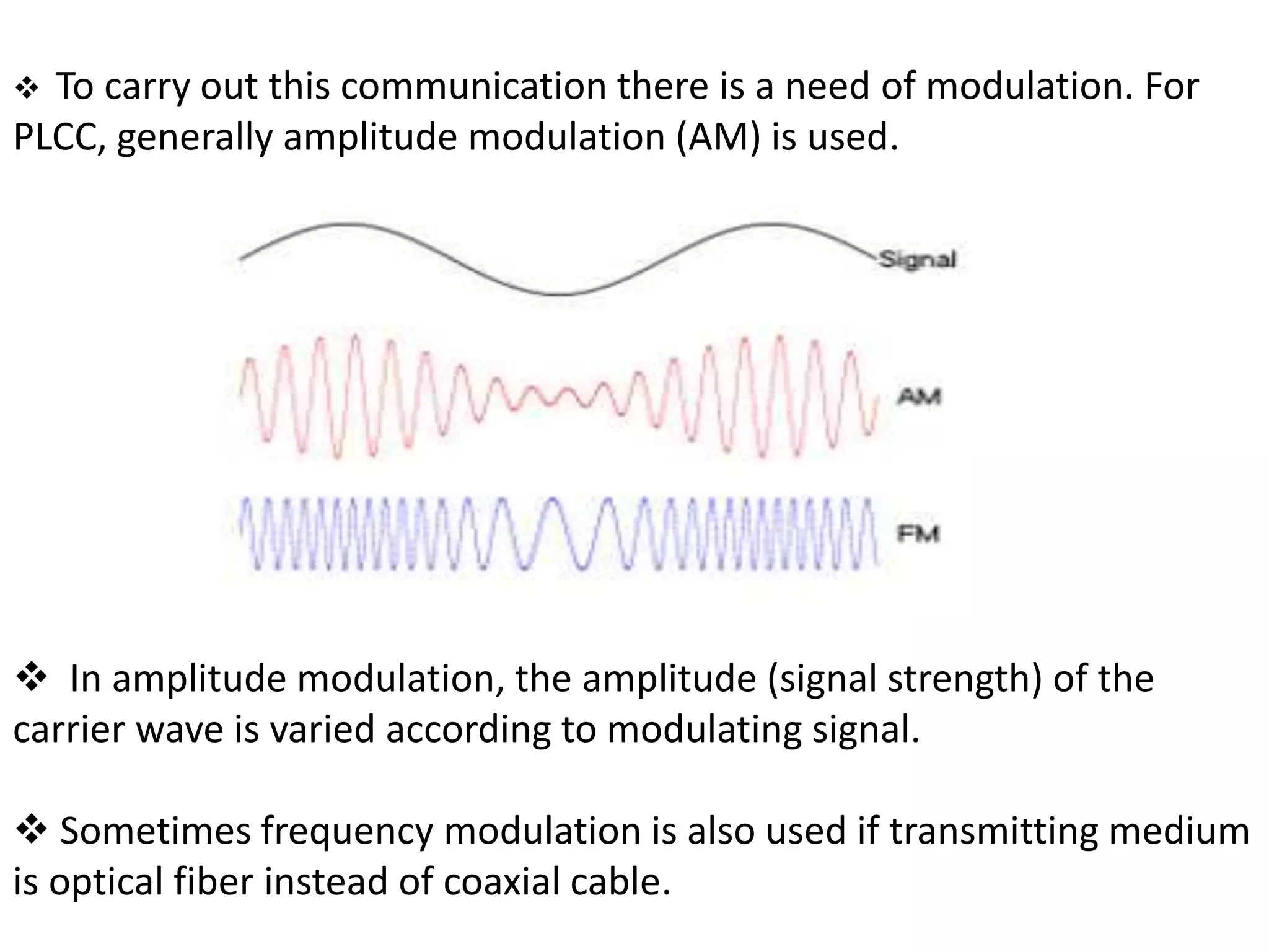
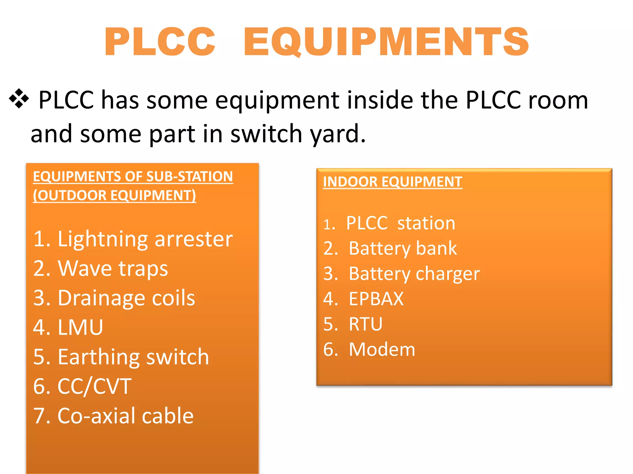
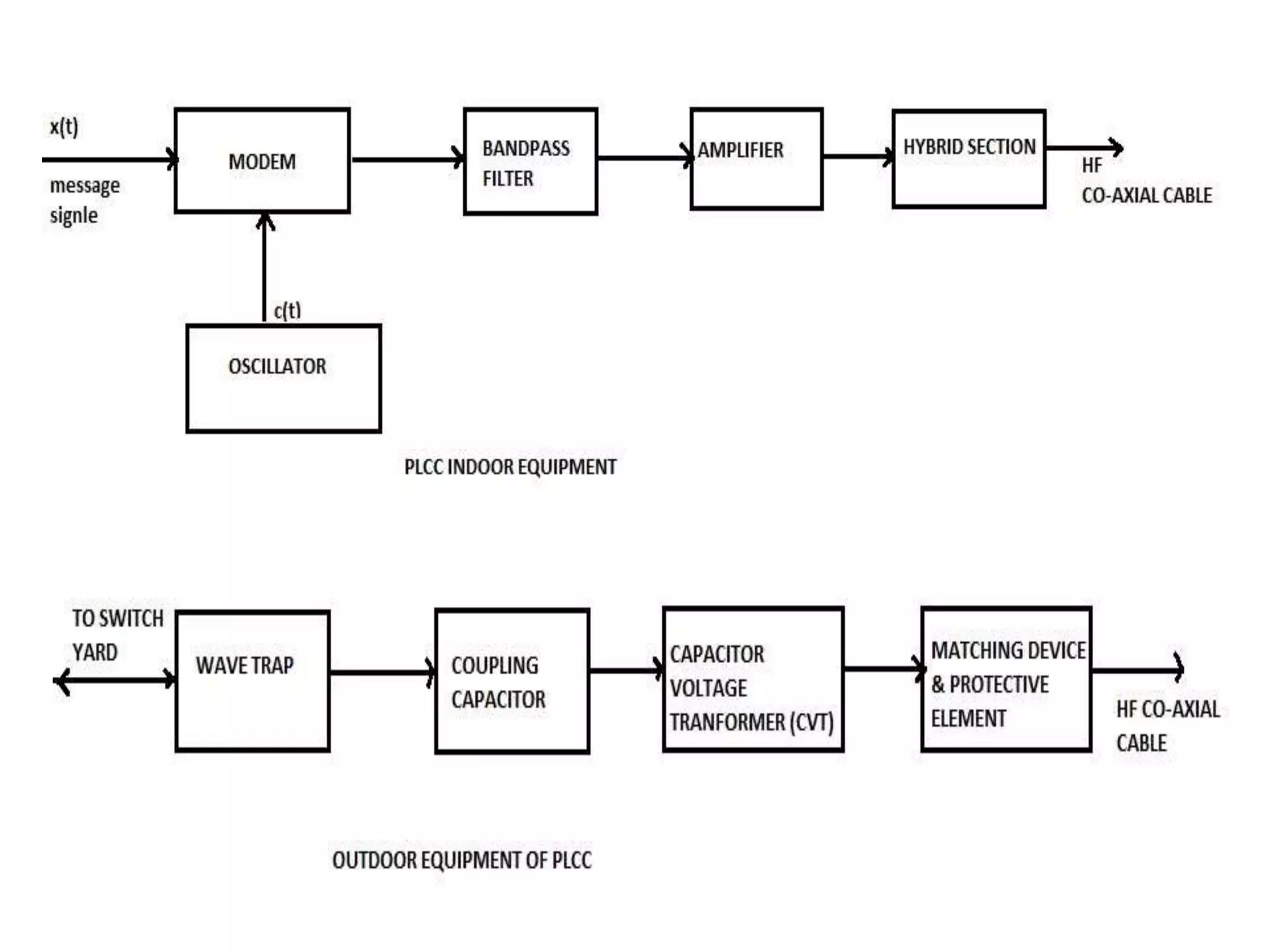
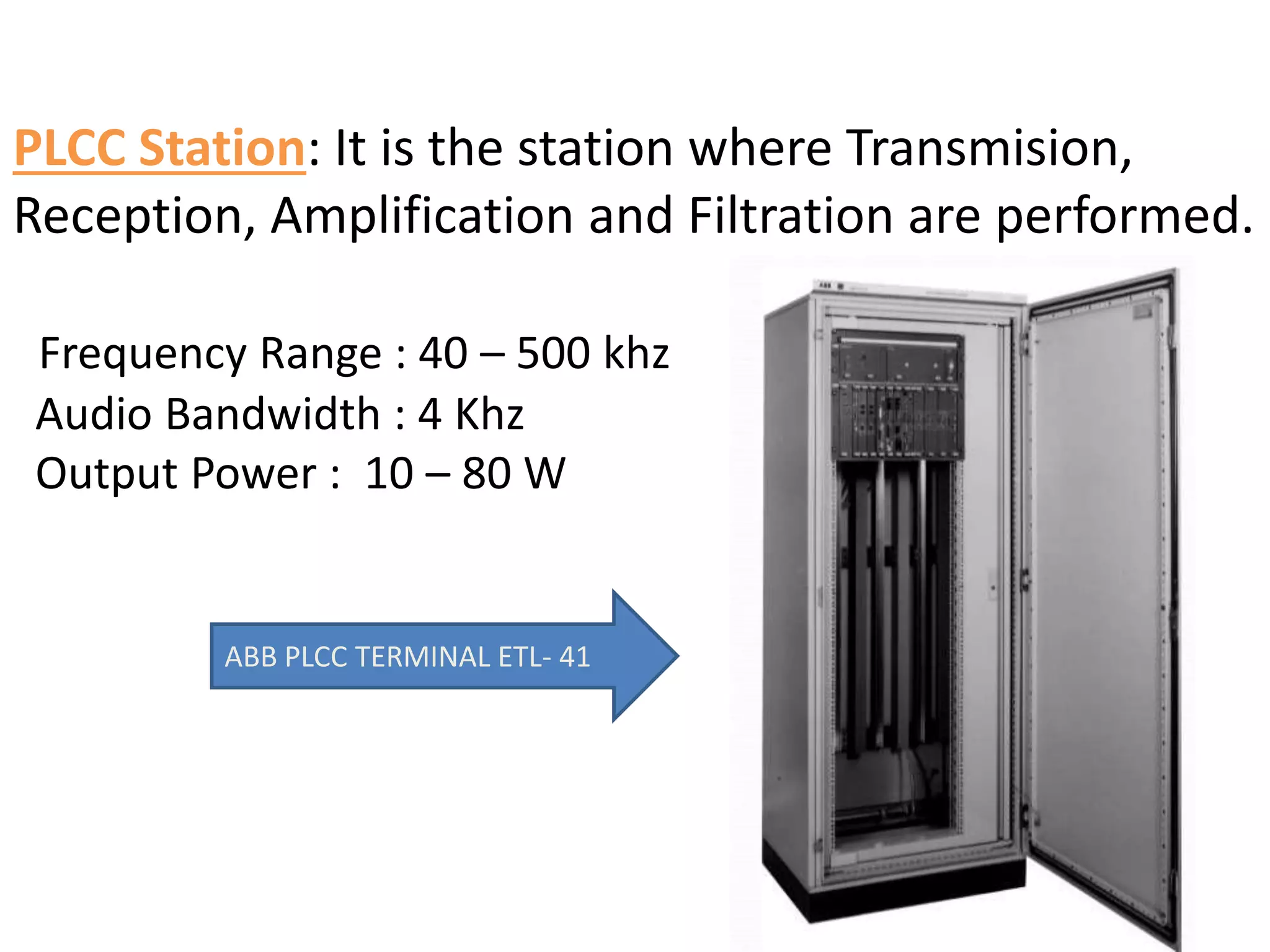
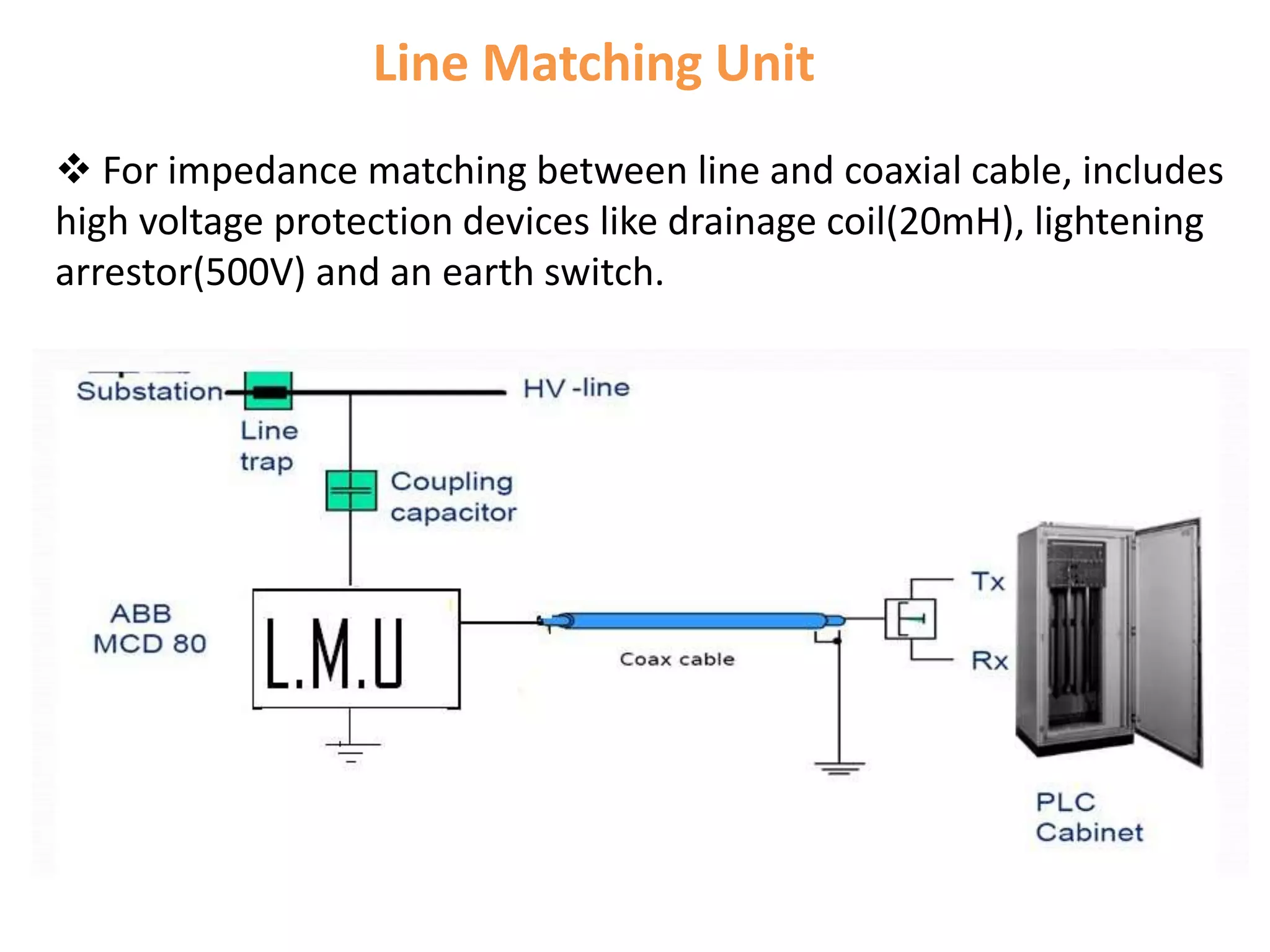
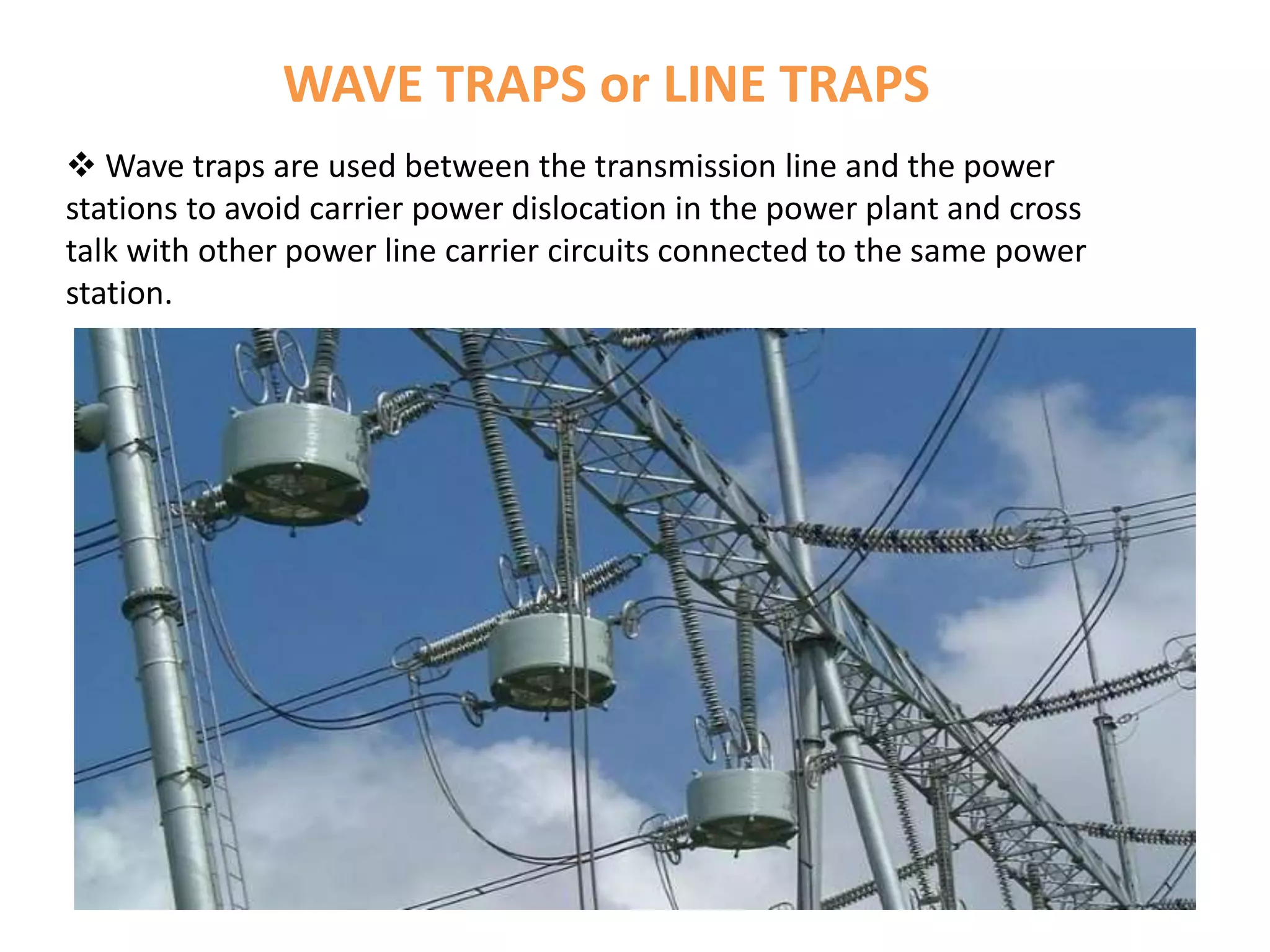
Power Line Carrier Communication (PLCC) is a communication method that uses electrical wiring to simultaneously carry both data and electric power. This makes power line communication one of the best means for networking. It is also known as power line carrier, power line digital subscriber line (PDSL), mains communication, power line telecommunications, or power line networking (PLN).
Presentation by Andreas Schleicher Tackling the School Absenteeism Crisis 30 ...
POWER LINE CARRIER COMMUNICATION
1. A
Practical Training Report
On
Power Line Carrier Communication (PLCC)
taken at
PLCC SECTION 132KV G.S.S. CHAMBAL POWER HOUSE, JAIPUR
Submitted in Partial fulfillment of Bachelor’s Degree in Technology
Rajasthan Technical University
Kota
Presented By :
Atul Kumar Sharma
B.Tech 7th SEM. (14ECIEC002)
CITM Sitapura, Jaipur
2. INTRODUCTION TO PLCC
POWER LINE CARRIER COMMUNICATION is the technology
which is used to communicate between electric substations
through existing electrical cables.
POWER LINE CARRIER COMMUNICATION is mainly used for
telecommunication, tele-monitoring and tele-protection
between electric substations through power lines at high
voltages.
The data can be transfer at 9.6Kbits/sec over many miles of
electrical cable.
4. BASIC PRINCIPAL OF PLCC
Power-line communications systems operate by adding a
modulated carrier signal on one conductor, on two conductors
or on all three conductors of a high-voltage AC transmission
line.
Different types of power-line communications use different
frequency bands. Since the power distribution system was
originally intended for transmission of AC power at typical
frequencies of 50 or 60 Hz.
Power wire circuits have only a limited ability to carry higher
frequencies.
5. To carry out this communication there is a need of modulation. For
PLCC, generally amplitude modulation (AM) is used.
In amplitude modulation, the amplitude (signal strength) of the
carrier wave is varied according to modulating signal.
Sometimes frequency modulation is also used if transmitting medium
is optical fiber instead of coaxial cable.
7. PLCC EQUIPMENTS
PLCC has some equipment inside the PLCC room
and some part in switch yard.
EQUIPMENTS OF SUB-STATION
(OUTDOOR EQUIPMENT)
1. Lightning arrester
2. Wave traps
3. Drainage coils
4. LMU
5. Earthing switch
6. CC/CVT
7. Co-axial cable
INDOOR EQUIPMENT
1. PLCC station
2. Battery bank
3. Battery charger
4. EPBAX
5. RTU
6. Modem
8.
9. PLCC Station: It is the station where Transmision,
Reception, Amplification and Filtration are performed.
Frequency Range : 40 – 500 khz
Audio Bandwidth : 4 Khz
Output Power : 10 – 80 W
ABB PLCC TERMINAL ETL- 41
11. Line Matching Unit
For impedance matching between line and coaxial cable, includes
high voltage protection devices like drainage coil(20mH), lightening
arrestor(500V) and an earth switch.
12. Lightning Arrestor : This is used for arresting any AC high
voltages spike entering to the LINE MATCHING UNIT.
13. Earth Switch: This is used for the maintenances of LMU. The
main function of Earth switch is to ground the trapped charges.
14. Control Voltage Transformer/Coupling Capacitors
It is connected between the line matching unit and the power lines to block
the high voltage entering to PLCC equipment.
It couples high frequency carries with power line.
16. WAVE TRAPS or LINE TRAPS
Wave traps are used between the transmission line and the power
stations to avoid carrier power dislocation in the power plant and cross
talk with other power line carrier circuits connected to the same power
station.
17.
18. ADVANTAGES
No separate wires are needed for communication purposes, as the power lines themselves
carry power as well as communication signals. hence the cost is less.
Power lines have appreciably higher mechanical strength compared with ordinary lines.
They would normally remain unaffected under the conditions, which might seriously
damage telephone lines.
Power lines have large cross-sectional area resulting in very low resistance per unit length.
Consequently carrier signals suffer much less attenuation than when they travel on telephone
lines of equal lengths.
Power lines are well insulated to provide only negligible leakage between conductors
and ground even in adverse weather conditions.
Largest spacing between conductors reduces capacitance, which results in smaller
attenuation at high frequencies. The large spacing also reduces the cross talk to a
considerable extent.
19. DISADVANTAGES
Proper care has to be taken to guard carrier equipment and persons using
them against high voltages and currents on the lines.
High voltage lines have transformer connections, attenuate carrier
currents. Sub-station equipments adversely affect the carrier currents.
Noise introduced by power lines is far more than in case of telephone lines.
This is due to the noise generated by discharge across insulators, corona and
switching processes.
The noise is also introduced in the signal due to bad weather conditions.