Downloaded 364 times

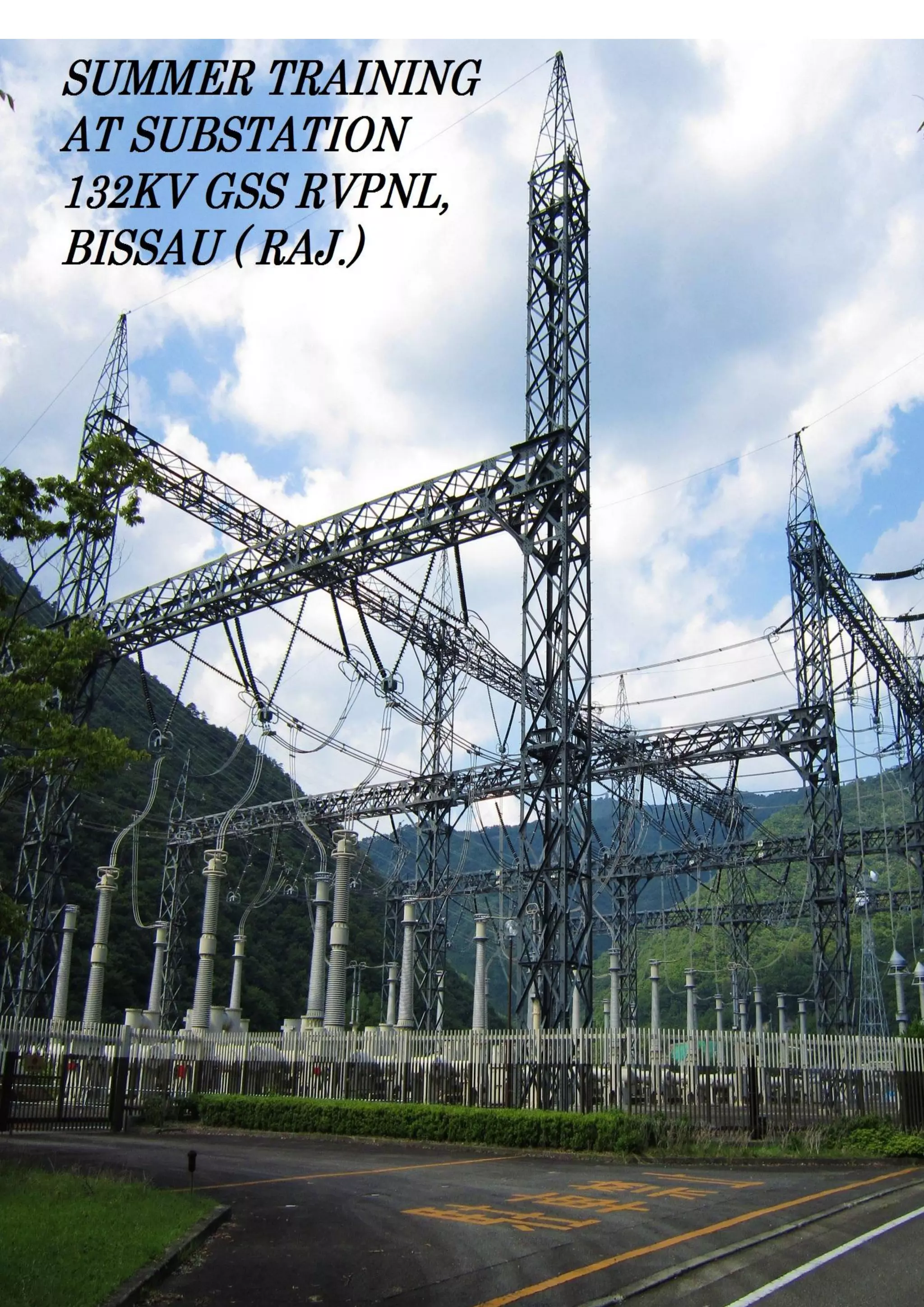
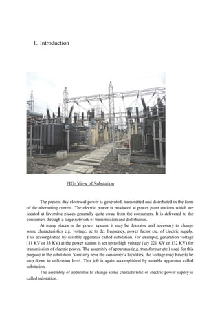
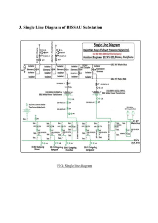


The document provides information about Tejveer Choudhary's industrial training at the 132 kV Bissau substation operated by RVPNL. It includes an acknowledgement expressing gratitude to the assistant engineer, Mr. Dilip Singh, for his guidance during the training. The document then covers various topics related to substation design and components, including earthing and bonding, transformer types, circuit breakers, protective relays, busbars, and other equipment.