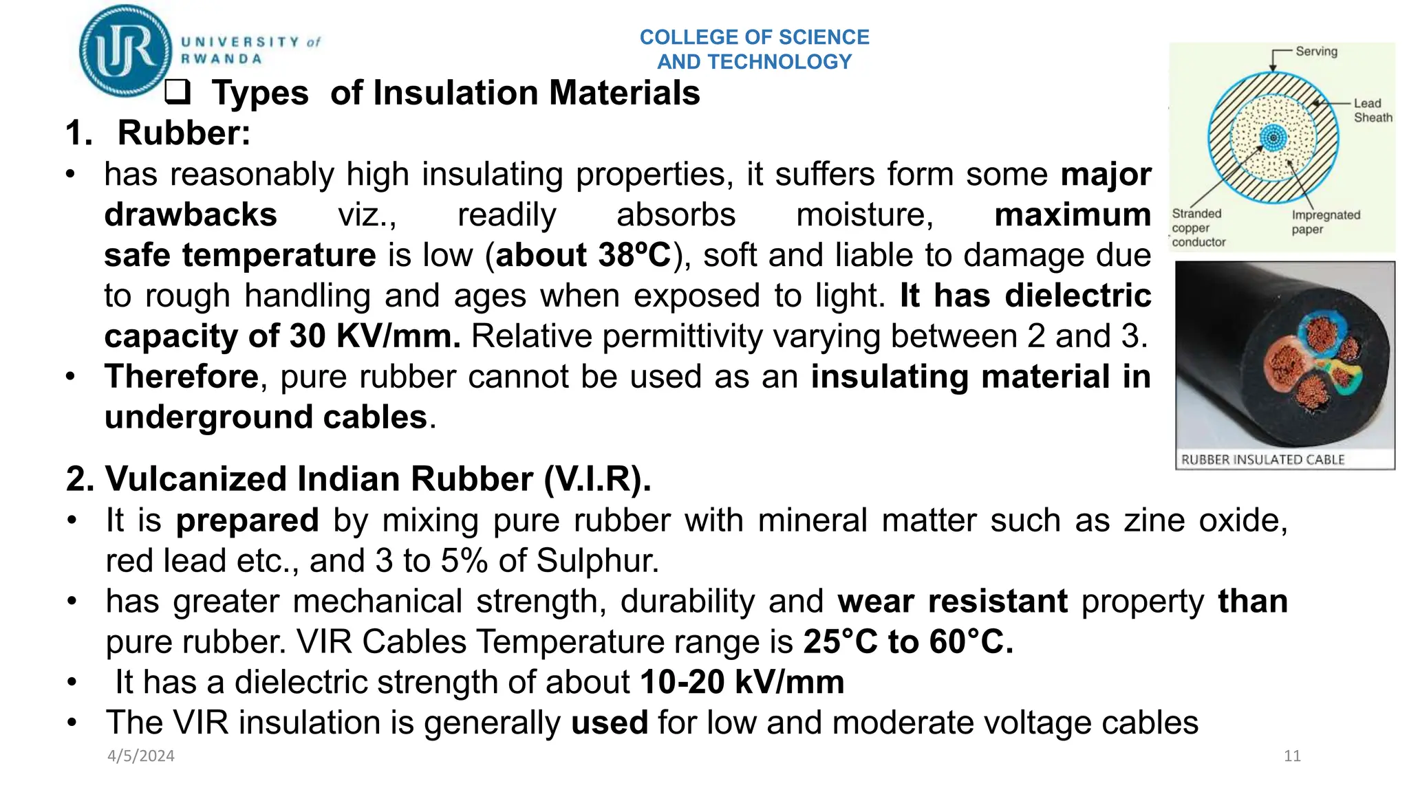
SlideShare a Scribd company logo
1 of 76
COLLEGE OF SCIENCE
AND TECHNOLOGY
4/5/2024 1
 Inductance of underground transmission lines, capacitance of
underground transmission lines, electric equivalent circuit of
underground transmission line under steady state;
 Types of cables; selection of right type of cable for a particular
system; parameter of single core cables; current rating; cable
installation; breakdown of cables; cable faults and their
location;
 The grid system with particular reference to Rwanda National
Grid system; Application of computer control on grid system.
Underground transmission line:
COLLEGE OF SCIENCE
AND TECHNOLOGY
4/5/2024 2
COLLEGE OF SCIENCE
AND TECHNOLOGY
 Introduction
4/5/2024 3
• Electric power can be transmitted or
distributed either by overhead system or
by underground cables.
• An underground cable consists of one or
more conductors covered with suitable
insulation and surrounded by a protecting
cover.
COLLEGE OF SCIENCE
AND TECHNOLOGY
 Applications Of Underground Cables
• Underground cables are employed where it is impracticable to use
overhead lines, such as:
 populated areas where municipal authorities prohibit overhead lines
for reasons of safety,
 around plants and substations where maintenance conditions do not
permit the use of overhead construction.
 Underground cables can also be used for supply connection in the
electrical plants, in generating stations, transmission system and
distribution systems, and so on.
4/5/2024 4
COLLEGE OF SCIENCE
AND TECHNOLOGY
4/5/2024 5
List of example of underground cable application for connecting one
apparatus with the others for the following:
- Supply power to the individual machine apparatus in electrical plants
- Connection between switchgear and individual load, group load
- Connection between auxiliary transformer and switchgear
-Sub transmission line between receiving substation and distribution
substation
-Submarine crossing
-Airports
-Etc.
COLLEGE OF SCIENCE
AND TECHNOLOGY
4/5/2024 6
 Requirements of underground cables
• Several types of cables are available, the type of cable to be used will
depend upon the working voltage and service requirements.
• In general, a cable must fulfil the following necessary requirements :
(i)The conductor used in cables should be tinned stranded copper or aluminium
of high conductivity. Stranding is done so that conductor may become flexible
and carry more current.
(ii) The conductor size should be such that the cable carries the desired load
current without overheating and causes voltage drop within permissible limits.
(iii) The cable must have proper thickness of insulation in order to give high
degree of safety and reliability at the voltage for which it is designed.
(iv) The cable must be provided with suitable mechanical protection so that it
may withstand the rough use in laying it.
(v) The materials used in the manufacture of cables should be such that there is
complete chemical and physical stability throughout.
COLLEGE OF SCIENCE
AND TECHNOLOGY
4/5/2024 7
 Cable Constructions
The main various part of
underground cables are:
• Cores or Conductors.
• Insulation.
• Metallic sheath.
• Bedding.
• Armouring.
• Serving.
COLLEGE OF SCIENCE
AND TECHNOLOGY
4/5/2024 8
• Cores or Conductors. To allow electricity to flow through them. A
cable may have one or more than one core (conductor) depending
upon the type of service for which it is intended. The conductors
are made of tinned copper or aluminium and are usually stranded
in order to provide flexibility to the cable.
• Insulation. To avoid leakage current in cable. Each core or
conductor is provided with a suitable thickness of insulation, the
thickness of layer depending upon the voltage to be withstood
by the cable. The commonly used materials for insulation are
impregnated paper, varnished cambric or rubber mineral
compound.
• Metallic sheath. To protect the cable from moisture, gases or
other damaging liquids (acids or alkalies) in the soil and
atmosphere, a metallic sheath of lead is provided over the
insulation
COLLEGE OF SCIENCE
AND TECHNOLOGY
4/5/2024 9
• Bedding. Over the metallic sheath is applied a layer of
bedding which consists of a fibrous material like jute or
hessian tape. The purpose of bedding is to protect the
metallic sheath against corrosion and from mechanical injury
due to armouring.
• Armouring. Over the bedding, armouring is provided which
consists of one or two layers of galvanized steel wire or steel
tape to protect the cable from mechanical injury. Armouring
may not be done in the case of some cables.
• Serving. (Outer cover ) In order to protect armouring from
atmospheric conditions, a layer of fibrous material (like jute)
similar to bedding is provided over the armouring. This is
known as serving.
COLLEGE OF SCIENCE
AND TECHNOLOGY
4/5/2024 10
 Insulating Materials for Cables
• the proper choice of insulating material for cables is of considerable
importance
• The insulating materials used in cables should have the following
properties:
 High insulation resistance to avoid leakage current.
 High dielectric strength to avoid electrical breakdown
 High mechanical strength to withstand mechanical handling.
 Unaffected by acids and alkalies to avoid chemical actions.
 Non-hygroscopic i.e. it should not absorb moisture from air or soil. The
moisture tends to decrease the insulation resistance and cause the
breakdown of the cable. In case the insulating material is hygroscopic, it
must be enclosed in a waterproof covering like lead sheath.
 Non-inflammable.
 Low cost so as to make the underground system a viable proposition.
COLLEGE OF SCIENCE
AND TECHNOLOGY
4/5/2024 11
1. Rubber:
• has reasonably high insulating properties, it suffers form some major
drawbacks viz., readily absorbs moisture, maximum
safe temperature is low (about 38ºC), soft and liable to damage due
to rough handling and ages when exposed to light. It has dielectric
capacity of 30 KV/mm. Relative permittivity varying between 2 and 3.
• Therefore, pure rubber cannot be used as an insulating material in
underground cables.
 Types of Insulation Materials
2. Vulcanized Indian Rubber (V.I.R).
• It is prepared by mixing pure rubber with mineral matter such as zine oxide,
red lead etc., and 3 to 5% of Sulphur.
• has greater mechanical strength, durability and wear resistant property than
pure rubber. VIR Cables Temperature range is 25°C to 60°C.
• It has a dielectric strength of about 10-20 kV/mm
• The VIR insulation is generally used for low and moderate voltage cables
COLLEGE OF SCIENCE
AND TECHNOLOGY
4/5/2024 12
3. Impregnated paper.
• It consists of chemically pulped paper and impregnated with some
compound such as paraffinic.
• This type of insulation has almost superseded the rubber insulation.
• it has the advantages of low cost, low capacitance, high dielectric
strength and high insulation resistance.
• The only disadvantage is that paper is hygroscopic. Since the paper
insulated cables have the tendency to absorb moisture, they are used
where the cable route has a few joints.
• It has the high dielectric strength (40 – 50 kV/mm) and continuous
temperature rating of 80oC. It is used in high voltage power cable
manufacturing
4. Varnished cambric.
• It is a cotton cloth impregnated and coated with varnish.
• The varnished cambric is hygroscopic, therefore, such cables are always provided
with metallic sheath.
• Its dielectric strength is about 4kV/mm and permittivity is 2.5 to 3.8.
COLLEGE OF SCIENCE
AND TECHNOLOGY
4/5/2024 13
 The PVC cables can be bent to smaller radii which make them particularly
suitable for laying in industrial places.
 As the mechanical properties (i.e., elasticity etc.) of PVC are not so good
as those of rubber, therefore, PVC insulated cables are generally used for
low and medium domestic lights and power installations.
 Due to a high dielectric, mechanical strength and exceptional resistance
to moisture, the PVC cables have almost completely replaced the paper
and rubber insulated cables in the range up to 11 kV.
5. Polyvinyl chloride (PVC).
 It is a thermoplastic synthetic compound. It is
generally used to insulate the cables.
 It has a good dielectric strength (17 kV/mm) and
maximum continuous temperature rating of 75oC.
COLLEGE OF SCIENCE
AND TECHNOLOGY
4/5/2024 14
6. XLPE Cables (Cross Linked Poly-ethene)
• This material has temperature range beyond 250 – 300 C
• This material gives good insulating properties. It is light in weight, small
overall dimensions, low dielectric constant and high mechanical strength,
low water absorption.
• These cables permit conductor temperature of 90 C and 250 C under
normal and short circuit conditions.
• Long-term working temperature can reach 90℃ and thermal life can
reach 40 years.
• These cables are suitable up to voltages of 33 KV.
COLLEGE OF SCIENCE
AND TECHNOLOGY
4/5/2024 15
 Classification of Cables
Cables for underground service may be classified
according to:
(i) the voltage for which they are manufactured
(ii)the type of insulating material used in their
manufacture
(iii) the number of Cores
 Classification according to the voltage
 Low-tension (L.T.) cables - up to 1000 V
 High-tension (H.T.) cables - up to 11,000 V
 Super-tension (S.T.) cables - from 22 kV to 33 kV
 Extra high-tension (E.H.T) cables - from 33 kV to 66 kV
 Extra super voltage cables - beyond 132 kV
COLLEGE OF SCIENCE
AND TECHNOLOGY
4/5/2024 16
COLLEGE OF SCIENCE
AND TECHNOLOGY
4/5/2024 17
 Classification of cable according to the type of
insulating material used in their manufacture
COLLEGE OF SCIENCE
AND TECHNOLOGY
4/5/2024 18
 Classification of cable according to the type of
insulating material used in their manufacture cont…..
COLLEGE OF SCIENCE
AND TECHNOLOGY
4/5/2024 19
 Classification of cable according to the type of
insulating material used in their manufacture cont…..
COLLEGE OF SCIENCE
AND TECHNOLOGY
4/5/2024 20
 Classification according to the number of Cores
• It may be:
(ii) single-core
(ii) two-core
(iii) three-core
(iv) four-core etc.
• For a 3-phase service, either 3-
single-core cables or three-core
cable can be used depending
upon the operating voltage and
load demand.
• A cable may have one or more than one core depending upon the
type of service for which it is intended.
COLLEGE OF SCIENCE
AND TECHNOLOGY
4/5/2024 21
 Cables for 3-Phase Service
• In practice, underground cables are generally required to deliver 3-phase
power. For the purpose, either three-core cable or three single core cables
may be used.
 For voltages up to 66 kV, 3-core cable (i.e., multi-core construction) is
preferred due to economic reasons.
 For voltages beyond 66 kV, the insulation required for that cable is too much
hence, single-core cables are used in order to prevent the thermal in cable.
 For higher voltages, 3 cored become too large and unwieldy hence, even
with some limitations we employ single cored cables
• The following types of cables are generally used for 3-phase service :
1. Belted cables — up to 11 kV
2. Screened cables — from 22 kV to 66 kV
3. Pressure cables — beyond 66 kV.
COLLEGE OF SCIENCE
AND TECHNOLOGY
4/5/2024 22
1. Belted cables
These cables are used for voltages up to
11kV but in extraordinary cases, their use
may be extended up to 22kV.
• The cores are not in circular shape.
• The cores are insulated from each
other by use of impregnated paper.
• The gaps are filled with fibrous
material like jute.
• The belt is covered with lead
sheath and provides flexibility as
well as a circular shape
COLLEGE OF SCIENCE
AND TECHNOLOGY
4/5/2024 23
2. Screened cables.
These cables are meant for use up to 33 kV, but in
particular cases their use may be extended to
operating voltages up to 66 kV.
The two types of screened cables are:
• H(Hochstetler )-Type cables
• S.L.(separate lead) Type cables
Screened cables (i) H-type cables
(ii) S.L. Type cables
COLLEGE OF SCIENCE
AND TECHNOLOGY
4/5/2024 24
H- Type cables :
• Designed by M. Hochstetler and hence named H-type cable.
• No paper belt in this type of cable.
• Each conductor is insulated with a paper, covered with a
metallic screen.
Advantages
• Perforations in the metallic screens assist in the complete impregnation
of the cable with the compound and thus the possibility of air pockets
or voids (vacuous spaces) in the dielectric is eliminated.
• Metallic screens increase the heat-dissipating power of the cable.
• The cores are laid in such a way that metallic screens make contact with one
another.
• The conducting belt (copper woven fabric tape) is wrapped round the three cores
COLLEGE OF SCIENCE
AND TECHNOLOGY
4/5/2024 25
Advantages
• Separate sheaths minimize the possibility of core-to-core breakdown.
• Bending of cables becomes easy due to the elimination of overall lead
sheath.
Disadvantage
• Three lead sheaths of S.L. cable are much thinner than the single
sheath of H-cable and, therefore, call for greater care in manufacture.
S.L.(separate lead) Cables :
• S.L. leads for Separate Lead Screened
Cables.
• Each core is insulated with impregnated
paper than covered by separate sheath
lead
COLLEGE OF SCIENCE
AND TECHNOLOGY
4/5/2024 26
3. Pressure Cables
• When the operating voltages are greater than 66 kV and up to
230 kV, pressure cables are used.
• In such cables, voids are eliminated by increasing the pressure
of compound and for this reason they are called pressure
cables.
• Two types of pressure cables viz oil-filled cables and gas
pressure cables are commonly used.
• Oil or gas is kept under pressure either within the cable sheath
itself or a containing pipe
COLLEGE OF SCIENCE
AND TECHNOLOGY
4/5/2024 27
(i) Oil-filled cables
• In case of oil filled cables, the channels or ducts
are provided within or adjacent to the cores,
through which oil under pressure is circulated.
COLLEGE OF SCIENCE
AND TECHNOLOGY
4/5/2024 28
Advantages :
• Thickness of insulation required is less.
• Thermal resistance is less.
• Possibility of voids is completely eliminated.
• Temperature range is high.
• Perfect impregnation is possible.
Disadvantages :
• Initial cost is very high.
• Long lengths are not possible.
• Oil leakage is serious problem.
• Complicated maintenance.
Oil-filled cables ……
COLLEGE OF SCIENCE
AND TECHNOLOGY
4/5/2024 29
ii) Gas Pressure Cables
• An inert gas like N at high pressure is introduced
lead sheath and dielectric.
• Gas like SF6 is also used in cables.
• Pressure is about 12-15 atmosphere.
• Working power factors is also high
Advantages :
• These can carry 1.5 times of the normal load current.
• Maintenance cost is small.
• No reservoirs or tanks required.
• Power factor is improved.
• Ionization and possible void completely eliminated.
Disadvantages :
• The only disadvantage is that the initial cost is extremely high.
COLLEGE OF SCIENCE
AND TECHNOLOGY
4/5/2024 30
4. SUPER TENSION (S.T.) CABLES
• The S.T. cables are intended for 132 kV
to 275 kV voltage levels.
• In such cables, the following methods
are specially used to eliminate the
possibility of void formation:
 Instead of solid type insulation, low
viscosity oils under pressure is used for
impregnation.
 Using inert gas at high pressure in
between the lead sheath & dielectric.
COLLEGE OF SCIENCE
AND TECHNOLOGY
4/5/2024 31
 Power Cable Installation methods
There are three main methods of Laying underground cables:
• Direct laying
• Draw in system
• Solid system
COLLEGE OF SCIENCE
AND TECHNOLOGY
4/5/2024 32
• A trench of about 1.5 meters deep and 45 cm wide is dug.
• Then the trench is covered with a 10 cm thick layer of fine sand.
• The cable is laid over the sand bed. The sand bed protects the
cable from the moisture from the ground.
• Then the laid cable is again covered with a layer of sand of about
10 cm thick.
• When multiple cables are to be laid in the same trench, a
horizontal or vertical spacing of about 30 cm is provided to
reduce the effect of mutual heating. Spacing between the cables
also ensures a fault occurring on one cable does not damage the
adjacent cable.
• The trench is then covered with bricks and soil to protect the
cable from mechanical injury.
 Direct Laying Of Underground Cables
COLLEGE OF SCIENCE
AND TECHNOLOGY
4/5/2024 33
Advantages
• Simpler and cheaper than the other two methods
• Heat generated in cables is easily dissipated in the ground.
• It is clean and safe
Disadvantages
• To install new cables for fulfilling an increased load demand,
completely new excavation has to be done which costs as much
as the new installation.
• Alterations in the cable network are not easy.
• Maintenance cost is higher.
• Identifying the location of a fault is difficult.
• This method can not be used in congested areas such as metro
cities where excavation is too expensive.
COLLEGE OF SCIENCE
AND TECHNOLOGY
4/5/2024 34
 Draw in system
• Draw in system cable layout methods is widely
used for heavily populated areas such as
urban cities and towns.
• the cables are layout in ducts or pipelines on
the ground with certain manholes
Draw in system Disadvantages
• It is very high initial cost
• Heat dissipation conditions are not good
• This method is suitable for congested areas
where excavation in expensive and
inconvenient
• This is generally used for short lenghts cable route such as in
workshops,road crossings where frequent digging is costlier and impossible
COLLEGE OF SCIENCE
AND TECHNOLOGY
4/5/2024 35
 Solid System
• In this system the cable is laid in open pipes or troughs dug
out in earth along the cable route
• The troughing is of cast iron or treated wood
• Troughing is filled with a bituminous after cable is laid
• It provides good mechanical strength
• the cables are filled with bituminous materials for providing
protection and avoid heat dissipation.
• Asphalt cover layer around the cable and bituminous
material area for further protection
Disadvantages
• More expensive than direct laid system
• Requires skilled labour and favourable weather conditions
• Due to poor heat dissipation facilities, the current carrying capacity of the cable is
reduced
• In view of these disadvantages, this method of laying underground cables is
rarely used nowadays
COLLEGE OF SCIENCE
AND TECHNOLOGY
4/5/2024 36
The depth of burial shall be sufficient to
protect the cable from damage imposed by
expected surface usage
• LV cable (1.1 kV) 0.75m
• MV cable (11 kV) 0.90 m
• HV cable (33 kV) 1.20 m
• Sand – covered with 150 mm
• Width of the trench 350 mm minimum
 Depth of Burial
COLLEGE OF SCIENCE
AND TECHNOLOGY
4/5/2024 37
 Calculation of high voltage cable parameters
COLLEGE OF SCIENCE
AND TECHNOLOGY
4/5/2024 38
 Insulation Resistance of a Single-Core Cable
Radius of conductor=r1
Radius of sheath=r2
small layer of insulation of
thickness dx at a radius x
This shows that insulation resistance of a cable is inversely
proportional to its length. In other words, if the cable length
increases, its insulation resistance decreases and vice-versa.
the leakage resistance is inversely proportional to the length of cable.
Solve example 11.1. up to 11.3 from pages 273-274
COLLEGE OF SCIENCE
AND TECHNOLOGY
4/5/2024 39
 Capacitance of a Single Core Cable
A single-core cable can be considered to be
equivalent to two long co-axial cylinders. The
conductor (or core) of the cable is the inner
cylinder while the outer cylinder is represented
by lead sheath which is at earth potential.
Consider a single core cable with conductor
diameter d and inner sheath diameter D
Conductor diameter=d
Inner sheath diameter=D
the charge per metre axial length of the cable be Q coulombs and ε be the
permittivity of the insulation material between core and lead sheath. Obviously ε =
ε0 εr where εr is the relative permittivity of the insulation.
COLLEGE OF SCIENCE
AND TECHNOLOGY
4/5/2024 40
Consider a cylinder of radius x metres and axial length 1 metre. The surface
area of this cylinder is
COLLEGE OF SCIENCE
AND TECHNOLOGY
4/5/2024 41
Solve example 11.1.
up to 11.6 from
pages 275-276
COLLEGE OF SCIENCE
AND TECHNOLOGY
4/5/2024 42
Example
Solution
A 33 kV, 50 Hz, 3-phase underground cable, 4 km long uses three single
core cables. Each of the conductor has a diameter of 2·5 cm and the radial
thickness of insulation is 0·5 cm. Determine (i) capacitance of the
cable/phase (ii) charging current/phase (iii) total charging kVAR. The relative
permittivity of insulation is 3.
COLLEGE OF SCIENCE
AND TECHNOLOGY
4/5/2024 43
 Dielectric Stress in a Single-Core Cable
• Under operating conditions, the insulation of a cable is
subjected to electrostatic forces. This is known as dielectric
stress. The dielectric stress at any point in a cable is the
potential gradient (or electric intensity) at that point.
• Consider a single core cable with core diameter d and internal
sheath diameter D. the electric intensity at a point x metres from
the centre of the cable is
• Electric intensity is equal to potential
gradient. Therefore, potential gradient g at a
point x metres from the centre of cable is
Potential difference V between
conductor and sheath is
from slide 41
COLLEGE OF SCIENCE
AND TECHNOLOGY
4/5/2024 44
• The potential gradient varies inversely as the distance x. Therefore, potential
gradient will be maximum when x is minimum i.e., when x = d/2 or at the
surface of the conductor and it will be minimum at x = D/2 or at sheath
surface.
 Maximum potential
gradient is
 Minimum potential
gradient is
The variation of stress in the dielectric is shown in the above fig. The dielectric
stress is maximum at the conductor surface and its value goes on
decreasing as we move away from the conductor.
COLLEGE OF SCIENCE
AND TECHNOLOGY
4/5/2024 45
• It may be noted that maximum stress is an important consideration in the
design of a cable.
• For instance, if a cable is to be operated at such a voltage that maximum stress
is 5 kV/mm, then the insulation used must have a dielectric strength of at least
5 kV/mm, otherwise breakdown of the cable will become inevitable.
Solve example 11.7. up to 11.9 ; pages 278-279
COLLEGE OF SCIENCE
AND TECHNOLOGY
4/5/2024 46
The maximum and minimum stresses in the dielectric of a single core cable
are 40 kV/cm (r.m.s.) and 10 kV/cm (r.m.s.) respectively. If the conductor
diameter is 2 cm, find : (i) thickness of insulation (ii) operating voltage
Example
Solution
COLLEGE OF SCIENCE
AND TECHNOLOGY
4/5/2024 47
 Capacitance of 3-Core Cables
The capacitance of an underground cable system is much more important than
that of overhead line because in cables:
(i) conductors are nearer to each other and to the earthed sheath
(ii) they are separated by a dielectric of permittivity much greater than that of air.
Since potential difference
exists between pairs of
conductors and between
each conductor and the
sheath, electrostatic fields
are set up in the cable as
shown in the above Fig.
COLLEGE OF SCIENCE
AND TECHNOLOGY
4/5/2024 48
These electrostatic fields give rise to core-core capacitances Cc and conductor-
earth capacitances Ce as shown in Fig. (ii).
The three Cc are delta connected whereas the three Ce are star connected, the
sheath forming the star point [See Fig. (iii)].
COLLEGE OF SCIENCE
AND TECHNOLOGY
4/5/2024 49
They lay of a belted cable makes it reasonable to assume equality of each Cc and
each Ce. The three delta connected capacitances Cc [See Fig. (i)] can be
converted into equivalent star connected capacitances as shown in Fig. (ii). It can
be easily shown that equivalent star capacitance Ceq is equal to three times the
delta capacitance Cc i.e. Ceq = 3Cc.
COLLEGE OF SCIENCE
AND TECHNOLOGY
4/5/2024 50
The system of capacitances shown in Fig. (iii)
reduces to the equivalent circuit shown in
Fig. (i). Therefore, the whole cable is
equivalent to three star-connected
capacitors each of capacitance [See Fig. (ii)]
COLLEGE OF SCIENCE
AND TECHNOLOGY
4/5/2024 51
 Current-Carrying Capacity of Underground Cables
• The safe current-carrying capacity of an underground cable is determined
by the maximum permissible temperature rise.
• The cause of temperature rise is the losses that occur in a cable which
appear as heat. These losses are :
(i) Copper losses in the conductors
(ii) Hysteresis losses in the dielectric
(iii) Eddy current losses in the sheath
The safe working conductor temperature is 65ºC for armoured cables and 50ºC
for lead-sheathed cables laid in ducts. The maximum steady temperature
conditions prevail when the heat generated in the cable is equal to the heat
dissipated. The heat dissipation of the conductor losses is by conduction
through the insulation to the sheath from which the total losses (including
dielectric and sheath losses) may be conducted to the earth. Therefore, in order
to find permissible current loading, the thermal resistivity of the insulation,
the protective covering and the soil must be known.
COLLEGE OF SCIENCE
AND TECHNOLOGY
4/5/2024 52
 Thermal Resistance
The thermal resistance between two points in a medium (e.g. insulation) is
equal to temperature difference between these points divided by the heat
flowing between them in a unit time i.e.
Thermal resistance(ºC per watt),
S=
Temperature difference
Heat flowing in a unit time(watt)
=
Temperature rise(𝑡)
Watts dissipated(𝑃)
=
𝑡
𝑃
Like electrical resistance, thermal resistance is directly proportional to
length l in the direction of transmission of heat and inversely proportional to
the cross-section area a at right angles to that direction.
where 𝒌 is the constant of proportionality
and is known as thermal resistivity.
COLLEGE OF SCIENCE
AND TECHNOLOGY
4/5/2024 53
 Thermal Resistance of Dielectric of a Single-Core Cable
Consider 1m length of the cable. The thermal resistance of
small element of thickness dx at radius x is
r = radius of the core in metre r1 = inside radius of the sheath
in metre k = thermal resistivity of the insulation
∴ Thermal resistance of the dielectric is
The thermal resistance of lead sheath is small and is generally neglected
in calculations.
COLLEGE OF SCIENCE
AND TECHNOLOGY
4/5/2024 54
 Permissible Current Loading
• When considering heat dissipation in underground cables, the various thermal
resistances providing a heat dissipation path are in series. Therefore, they
add up like electrical resistances in series. Consider a cable laid in soil.
• Let I = permissible current per conductor; n = number of conductors ;
R = electrical resistance per metre length of the conductor at the working temperature
S = total thermal resistance (i.e. sum of thermal resistances of dielectric and soil) per
metre length and t = temperature difference (rise) between the conductor and the soil
• Neglecting the
dielectric and
sheath losses, we
have,
𝑷𝒐𝒘𝒆𝒓 𝒅𝒊𝒔𝒔𝒊𝒑𝒂𝒕𝒆𝒅 = 𝒏𝑰𝟐𝑹
𝑷𝒐𝒘𝒆𝒓 𝒅𝒊𝒔𝒔𝒊𝒑𝒂𝒕𝒆𝒅 =
𝑻𝒆𝒎𝒑𝒆𝒓𝒂𝒕𝒖𝒓𝒆 𝒓𝒊𝒔𝒆
𝑻𝒉𝒆𝒓𝒎𝒂𝒍 𝒓𝒆𝒔𝒊𝒔𝒕𝒂𝒏𝒄𝒆
Or n 𝑰𝟐𝑹 =
𝒕
𝑺
Permissible current
per conductor in given
by;
• It should be noted that when cables are laid in proximity to each other, the
permissible current is reduced further on account of mutual heating.
COLLEGE OF SCIENCE
AND TECHNOLOGY
4/5/2024 55
A single-core cable is laid in the ground, the core diameter being 30 mm and the
dielectric thickness 40 mm. The thermal resistivity of the dielectric is 5 thermal
ohm-metres and the thermal resistance between the sheath and the ground
surface is 0·45 thermal ohm per metre length of the cable. Neglecting dielectric
and sheath losses, estimate the maximum permissible current loading if the
temperature difference between the conductor and the ground surface is not to
exceed 55ºC. The electrical resistance of the cable is 110 µΩ per metre length.
Solution.
The thermal resistance of the dielectric
of the cable is
Example.
Here t = 55ºC ; n = 1,
R = 110 × 10−6 Ω ; S = 1·48
COLLEGE OF SCIENCE
AND TECHNOLOGY
4/5/2024 56
 Types of Cable Faults
• Cables are generally laid in the ground or in ducts in the underground
distribution system. For this reason, there are little chances of faults in
underground cables. However, if a fault does occur it is difficult to locate
and repair the fault because conductors are not visible.
• The causes of damage to the lead sheath are: crystallization of the lead
through vibration; chemical action on the lead when buried in the earth
and insufficiently protected; and mechanical damage.
• Main equipment to determine cable fault is ohmmeter beside that, a
few test can be done to determine cable fault such as :
1. Continuity Test
2. Insulation Resistance Test.
• Cable Fault Location instruments (cable fault locators) are used for
short circuit faults , cable cuts, resistive faults, intermittent faults, and
sheath faults.
COLLEGE OF SCIENCE
AND TECHNOLOGY
4/5/2024 57
Major factors that cause failure of underground cable are:
 Damaged accidentally by external mechanical means, like external
damage due to digging
 Damage was caused as a result of mishandling the cable during
layout(Excessive pull, Sharp bend, Accident crush).
 Poor workmanship in cable jointing. The cables are jointed together with
poor workmanship can lead to cable faults after a period of time.
 Natural causes due to aging of cable. May occur due to deterioration of
insulation due to aging or irreversible change of material properties after
exposure to an environment for an interval of time
 Damaged caused by movement of soil and erosion
COLLEGE OF SCIENCE
AND TECHNOLOGY
4/5/2024 58
• The following are the faults most likely to occur in underground
cables:
1) open circuit fault
2) short circuit fault
3) earth fault
COLLEGE OF SCIENCE
AND TECHNOLOGY
4/5/2024 59
 Open circuit fault
• When the conductor of cable is broken or joint is pulled out there is no
current in the cable it is called open circuit fault.
• The open circuit fault can be checked by Megger. For this purpose, three
measurements are to be carried out between R-Y, Y-B, B-R. The two
conductors of the 3-core cable at the far end are shorted.
• The resistance between two conductors is measured by a megger and it will
indicate zero resistance in the circuit of the conductor that is not broken. If
the continuity of the cable is sound, insulation resistance from one end is
sufficient.
• However, if the conductor is broken, the megger will indicate infinite
resistance in its circuit
COLLEGE OF SCIENCE
AND TECHNOLOGY
4/5/2024 60
 Short circuit fault
• When the insulation between two cable or two cores of a multi-core cable
gets damaged, the currents start flowing from one cable to another cable
or from one core to another core of a multi-core cable directly(without
passing through core).
• When two conductors of a multi-core cable come in electrical contact
with each other due to insulation failure, it is called a short circuit fault.
• Again, we can seek the help of a megger to check this fault.
• For this purpose the two terminals of the megger are connected to any two
conductors.
• If the megger gives zero reading, it indicates short circuit fault between
these conductors. If the megger will indicate infinite resistance in its circuit,
no short circuit
• The same steps is repeated for other conductors taking two a time.
COLLEGE OF SCIENCE
AND TECHNOLOGY
4/5/2024 61
 Ground or Earth Faults (Break-down of cable insulation)
• When the insulation of the cable gets damaged, the current start
flowing from core to earth or to cable sheath.
• When the conductor of a cable comes in contact with earth, it is
called earth fault or ground fault.
• To identify this fault, one terminal of the megger is connected to the
conductor and the other terminal connected to earth.
• If the megger indicates zero reading, it means the conductor is
earthed. The same procedure is repeated for other conductors of the
cable
COLLEGE OF SCIENCE
AND TECHNOLOGY
4/5/2024 62
• FAULT LOCATION PROCEDURE
The proper sequence of cable fault location are as follows:
 Analysis of fault
 Pre-location
 Pin Pointing
 Confirmation and re-test
https://www.cablejoints.co.uk/upload/Cable_Locating,_Detection_&_Cable_Fault_Finding___
Guidebook.pdf
• By repairing and re-testing, we ensure that the
underground cable fault is corrected; all the while
ensuring safety of field personnel.
COLLEGE OF SCIENCE
AND TECHNOLOGY
4/5/2024 63
 Analysis of Cable Fault
Analysis of cable fault normally consists of insulation resistance(IR) test and
continuity test
To analyze a cable fault is to determine and confirm the nature or characteristics
of the fault.
1. Insulation resistance(IR) test, Six
measurement are to be taken R-E, Y-
E, B-E, R-Y, Y-B, B-R.
2. Continuity Test, this test will determine
whether any of the cable is open
circuited. Three measurements are to be
carried out between R-Y, Y-B, B-R
https://slideplayer.com/slide/16374650/
COLLEGE OF SCIENCE
AND TECHNOLOGY
4/5/2024 64
Analysis of Cable Fault cont…
COLLEGE OF SCIENCE
AND TECHNOLOGY
4/5/2024 65
 Pre- Location of fault
• Pre-location is the application of a test at the terminals of a given cable to
give an indication of the distance to the fault from the test point.
• The purpose of pre-location is to give an indication, as quick as possible, of
the vicinity in which to commence the final pin-pointing tests.
COLLEGE OF SCIENCE
AND TECHNOLOGY
4/5/2024 66
 PIN POINTING
Pin Pointing is the application of a test that positively confirms the exact position of the
fault.
Before the commencement of pinpointing, the pre-located fault distance should be
marked on the cable route which is measured using a trumpeter. Pinpointing is
normally carried out by the shock wave discharge method.
The fault can be detected by the use of a semisphone.
 Confirmation and Re-Test
After the pin-pointed position of the fault has been marked and exposed, check for
physical sign of fault. If there is the fault is confirm.
After confirmation, the fault should be cut away, IR and continuity test should be
carried out on the remaining cable sections to determine the soundeness of these cable
sections. The insulation resistance test are again carried out after jointing followed by
pressure test before supply can be restored.
While undertaking the entire process of pinpointing cable fault, identifying appropriate
cable and repairing and re-testing, ensure that all essential safety precautions are
followed.
COLLEGE OF SCIENCE
AND TECHNOLOGY
4/5/2024 67
 Location Cable Fault in an Underground Cables
• Cable fault locator is a combination of Surge generator, Reflectometer and
Digipoint which are used for fault location in LT up to 11kV cables
• Van Mounted Cable Fault Locator, System designed for locating fault in LT to HT
underground cables
• The underground cable fault distance
locator is develop to detect the exact
fault location and the distance of
underground cable fault from based
station in kilometers as the system will
detect the faulted cable on underground
and will send the information to the
control room by using a relay.
COLLEGE OF SCIENCE
AND TECHNOLOGY
4/5/2024 68
 Surge generator
• It is used to produce high voltage surges,
perform DC high voltage testing and
provide the burning facility.
• Perform DC high voltage testing up to
16kV to find out which phase is faulty and
determine its breakdown voltage and
leakage current.
https://pdf.indiamart.com/impdf/23056748430/MY-1084010/underground-power-cable-
fault-locators-suitable-from-lt-to-ht-11kv-cables.pdf
1. Cable fault locator
COLLEGE OF SCIENCE
AND TECHNOLOGY
4/5/2024 69
• It is a digital time domain reflectometer used for finding the distance to the fault
from one end of the cable (Pre-Location).
 Reflectometer
• Pulse Echo(TDR), Impulse current(ICM)& Decay method
provided to get the distance to almost all types of faults
 Pulse Echo Method
Low voltage pulses are injected into the cable to locate open or
short circuit low resistive faults up to 200 ohm (measured by
multimeter) only. Provides total length of the cable fault.
The distance to the fault Lf (m) is given by Lf = T x Vp/2
Where: T, the duration of the pulse transmitted, till the pulse
is reflected back from the point of irregularity, If the fault
distance is Lf, the velocity of propagation (VOP) is Vp
The waveform generated can be monitored using an
oscilloscope
COLLEGE OF SCIENCE
AND TECHNOLOGY
4/5/2024 70
 Impulse Current Method (ICM)
High voltage surges with the help of surge generator are injected into
the power cables. It gives the fault distance of almost all types of faults
including low resistive, high resistive and intermittent faults.
 Decay Method
Decay method is most suitable for accurate pre-location of Flashing
faults
 Interactive Software
The interactive menu based graphical user interface makes it easy for even
a layman to pre-locate the fault distance. The software automatically saves
all the test results for future review and analysis with a huge storage
capacity of more than 100,000 graphs. It also allows us to compare any 5
selected graphs to review the fault conditions for more accurate result.
COLLEGE OF SCIENCE
AND TECHNOLOGY
4/5/2024 71
 Digi point
• It is used with a Surge Generator to determine the exact position of faults in
underground power cables. Pinpointing the exact location of the fault
• Magnetic and Acoustic signal strength through bar graph and digits on LCD
• Route indication of cable under test
It indicates the route of the cable under test by
sensing and amplifying the electromagnetic
signals produced at the time of surging and displays
the magnetic strength of those signals through
strength bars and digits on an LCD screen
• The surge generated by the surge generator will create an
acoustic signal at the fault point. The Digipoint displays the
strength of that signal through strength bars and digits on an
LCD screen. The headphones help users to hear the sound
generated.
https://www.youtube.com/watch?v=33qL3HR0HGo&t=1356s
COLLEGE OF SCIENCE
AND TECHNOLOGY
4/5/2024 72
2. Van Mounted Cable Fault Locator
• System designed for locating fault in LT to HT underground
cables, with system integrated and easy operation.
• The Cable fault locating van system is used to perform DC hi-
pot/ burn/ proof test, pre-location of fault distance, and pinpoint
underground cable fault by acoustic method with the help of
suitable DIGIPOINT in power transmission and distribution
with cable networks or service provider companies.
1.Automatic operating mode selection.
2.Convenient, fully automatic system operation with computerized
touch screen.
3.Safety status monitoring on display.
4.Cable library to store the traces.
• Responsible for all the functions from computerized touch
screen operating unit.
5.Separate high voltage unit from operation unit for the safety of operator
https://pdf.indiamart.com/impdf/23755209673/1084010/
automatic-cable-fault-locator-model-t-1032-20a-.pdf
COLLEGE OF SCIENCE
AND TECHNOLOGY
4/5/2024 73
• All fault-finding methods such as DC Testing, Fault Conditioning/ Limited
Burning Capability, Suitable Thumper for Pinpointing are provided in the
Surge Generator unit.
• DC Testing is used for checking the dielectric strength of insulation in the cable
and to identify and confirm fault conditions with a test voltage up to 40kV
• All pre-location methods such as PEM(Pulse Echo Method), ICM(Impulse
Current Method), ARM(Arc Reflection method)/SIM/MIM(Single Impulse Method
/ Multiple Impulse Method and DECAY method are provided in the system for
determination of high resistive faults for HT method
https://www.youtube.com/watch?v=33qL3HR0HGo&t=1356s
COLLEGE OF SCIENCE
AND TECHNOLOGY
4/5/2024 74
 Advantages of underground cables:
• less liable to damage through storms or lightning,
• low maintenance cost,
• less chance of faults,
• smaller voltage drop as the Inductive reactance of O.H.T. Lines is more
• better general appearance.
• Conserve valuable land in urban areas and avoid danger to the persons
from accessibility of high-voltage power
 Disadvantages of underground cables:
• The major drawback is that they have greater installation cost and introduce
insulation problems at high voltages compared with equivalent overhead
system.
• Capacitance and charging current is high in case of underground cables,
so that for long distance power transmission, the charging current is very high
results in over voltages problems.
COLLEGE OF SCIENCE
AND TECHNOLOGY
4/5/2024 75
Comparison of Overhead vs underground power lines cables
COLLEGE OF SCIENCE
AND TECHNOLOGY
4/5/2024 76
 Transmission: Underground may be 4-20 times Overhead.
 Sub transmission: Underground may be 4-20 times Overhead
 Distribution: Underground may be 2-10 times Overhead
 Summary of Costs: Overhead vs. Underground

More Related Content

Similar to underground of electrical power system.pptx

Comparative study of power cables and testing as per indian standards
Comparative study of power cables and testing as per indian standardsComparative study of power cables and testing as per indian standards
Comparative study of power cables and testing as per indian standardsIAEME Publication
 
Under ground cables
Under ground cablesUnder ground cables
Under ground cablesMohsin Mulla
 
Under ground cables presention
Under ground cables presentionUnder ground cables presention
Under ground cables presentionRazu Khan
 
Under ground cables
Under ground cablesUnder ground cables
Under ground cablesParth Kharva
 
Electrical wiring project
Electrical wiring projectElectrical wiring project
Electrical wiring projectsam zion
 
construction of underground cable
construction of underground cableconstruction of underground cable
construction of underground cableRajal Patel
 
Underground Cables.pptx
Underground Cables.pptxUnderground Cables.pptx
Underground Cables.pptxkarthik prabhu
 
8-step-by-step-processes.9772018.pptx
8-step-by-step-processes.9772018.pptx8-step-by-step-processes.9772018.pptx
8-step-by-step-processes.9772018.pptxPTD QUYCOCTU
 
8 step-by-step processes of manufacturing of electrical cable
8 step-by-step processes of manufacturing of electrical cable8 step-by-step processes of manufacturing of electrical cable
8 step-by-step processes of manufacturing of electrical cableDevanshVarma1
 
Introduction to power system power point ch-4&5.pdf
Introduction to power system power point ch-4&5.pdfIntroduction to power system power point ch-4&5.pdf
Introduction to power system power point ch-4&5.pdfGetahunShankoKefeni
 
cable,Different distribution lines and Insulator
cable,Different distribution lines and Insulatorcable,Different distribution lines and Insulator
cable,Different distribution lines and InsulatorSuryakant Morey
 
Prysmian Mine Master Electrical Cables For Mining Industry
Prysmian Mine Master Electrical Cables For Mining IndustryPrysmian Mine Master Electrical Cables For Mining Industry
Prysmian Mine Master Electrical Cables For Mining IndustryThorne & Derrick International
 

Similar to underground of electrical power system.pptx (20)

Comparative study of power cables and testing as per indian standards
Comparative study of power cables and testing as per indian standardsComparative study of power cables and testing as per indian standards
Comparative study of power cables and testing as per indian standards
 
Under ground cables
Under ground cablesUnder ground cables
Under ground cables
 
Under ground cables presention
Under ground cables presentionUnder ground cables presention
Under ground cables presention
 
Underground cables
Underground cablesUnderground cables
Underground cables
 
Under ground cables
Under ground cablesUnder ground cables
Under ground cables
 
Electrical wiring project
Electrical wiring projectElectrical wiring project
Electrical wiring project
 
Types of cables
Types of cablesTypes of cables
Types of cables
 
construction of underground cable
construction of underground cableconstruction of underground cable
construction of underground cable
 
Underground Cables.pptx
Underground Cables.pptxUnderground Cables.pptx
Underground Cables.pptx
 
Underground cables
Underground cablesUnderground cables
Underground cables
 
8-step-by-step-processes.9772018.pptx
8-step-by-step-processes.9772018.pptx8-step-by-step-processes.9772018.pptx
8-step-by-step-processes.9772018.pptx
 
8 step-by-step processes of manufacturing of electrical cable
8 step-by-step processes of manufacturing of electrical cable8 step-by-step processes of manufacturing of electrical cable
8 step-by-step processes of manufacturing of electrical cable
 
Introduction to power system power point ch-4&5.pdf
Introduction to power system power point ch-4&5.pdfIntroduction to power system power point ch-4&5.pdf
Introduction to power system power point ch-4&5.pdf
 
Underground cables
Underground cablesUnderground cables
Underground cables
 
Power cables
Power cablesPower cables
Power cables
 
Underground cables
Underground cablesUnderground cables
Underground cables
 
cable,Different distribution lines and Insulator
cable,Different distribution lines and Insulatorcable,Different distribution lines and Insulator
cable,Different distribution lines and Insulator
 
types of wire.pptx
types of wire.pptxtypes of wire.pptx
types of wire.pptx
 
Prysmian Mine Master Electrical Cables For Mining Industry
Prysmian Mine Master Electrical Cables For Mining IndustryPrysmian Mine Master Electrical Cables For Mining Industry
Prysmian Mine Master Electrical Cables For Mining Industry
 
Underground cables
Underground cablesUnderground cables
Underground cables
 

More from JoseeMusabyimana

Frequency control & Voltage control.pptx
Frequency control & Voltage control.pptxFrequency control & Voltage control.pptx
Frequency control & Voltage control.pptxJoseeMusabyimana
 
3_Transmission_of_Electric_Energy.power point presentation
3_Transmission_of_Electric_Energy.power point presentation3_Transmission_of_Electric_Energy.power point presentation
3_Transmission_of_Electric_Energy.power point presentationJoseeMusabyimana
 
Admittance model and Power flow study.pptx
Admittance model and Power flow study.pptxAdmittance model and Power flow study.pptx
Admittance model and Power flow study.pptxJoseeMusabyimana
 
Overview of power systems_unit 1_Lect1.pptx
Overview of power systems_unit 1_Lect1.pptxOverview of power systems_unit 1_Lect1.pptx
Overview of power systems_unit 1_Lect1.pptxJoseeMusabyimana
 
analyze the current and voltage distr along distribution line.pptx
analyze the current and voltage  distr along distribution line.pptxanalyze the current and voltage  distr along distribution line.pptx
analyze the current and voltage distr along distribution line.pptxJoseeMusabyimana
 
EPE3163_Hydro power stations_Unit2_Lect2.pptx
EPE3163_Hydro power stations_Unit2_Lect2.pptxEPE3163_Hydro power stations_Unit2_Lect2.pptx
EPE3163_Hydro power stations_Unit2_Lect2.pptxJoseeMusabyimana
 
ENE3263_Transmission and Distribution of Energy module content.pptx
ENE3263_Transmission and Distribution of Energy module content.pptxENE3263_Transmission and Distribution of Energy module content.pptx
ENE3263_Transmission and Distribution of Energy module content.pptxJoseeMusabyimana
 
ENE3263_Transmission and Distribution of Energy class exercise1.pptx
ENE3263_Transmission and Distribution of Energy class exercise1.pptxENE3263_Transmission and Distribution of Energy class exercise1.pptx
ENE3263_Transmission and Distribution of Energy class exercise1.pptxJoseeMusabyimana
 
ENE3263_Transmission and Distribution of Energy class exercise1.pptx
ENE3263_Transmission and Distribution of Energy class exercise1.pptxENE3263_Transmission and Distribution of Energy class exercise1.pptx
ENE3263_Transmission and Distribution of Energy class exercise1.pptxJoseeMusabyimana
 
ENE3263_Transmission and Distribution of Energy module content.pptx
ENE3263_Transmission and Distribution of Energy module content.pptxENE3263_Transmission and Distribution of Energy module content.pptx
ENE3263_Transmission and Distribution of Energy module content.pptxJoseeMusabyimana
 

More from JoseeMusabyimana (10)

Frequency control & Voltage control.pptx
Frequency control & Voltage control.pptxFrequency control & Voltage control.pptx
Frequency control & Voltage control.pptx
 
3_Transmission_of_Electric_Energy.power point presentation
3_Transmission_of_Electric_Energy.power point presentation3_Transmission_of_Electric_Energy.power point presentation
3_Transmission_of_Electric_Energy.power point presentation
 
Admittance model and Power flow study.pptx
Admittance model and Power flow study.pptxAdmittance model and Power flow study.pptx
Admittance model and Power flow study.pptx
 
Overview of power systems_unit 1_Lect1.pptx
Overview of power systems_unit 1_Lect1.pptxOverview of power systems_unit 1_Lect1.pptx
Overview of power systems_unit 1_Lect1.pptx
 
analyze the current and voltage distr along distribution line.pptx
analyze the current and voltage  distr along distribution line.pptxanalyze the current and voltage  distr along distribution line.pptx
analyze the current and voltage distr along distribution line.pptx
 
EPE3163_Hydro power stations_Unit2_Lect2.pptx
EPE3163_Hydro power stations_Unit2_Lect2.pptxEPE3163_Hydro power stations_Unit2_Lect2.pptx
EPE3163_Hydro power stations_Unit2_Lect2.pptx
 
ENE3263_Transmission and Distribution of Energy module content.pptx
ENE3263_Transmission and Distribution of Energy module content.pptxENE3263_Transmission and Distribution of Energy module content.pptx
ENE3263_Transmission and Distribution of Energy module content.pptx
 
ENE3263_Transmission and Distribution of Energy class exercise1.pptx
ENE3263_Transmission and Distribution of Energy class exercise1.pptxENE3263_Transmission and Distribution of Energy class exercise1.pptx
ENE3263_Transmission and Distribution of Energy class exercise1.pptx
 
ENE3263_Transmission and Distribution of Energy class exercise1.pptx
ENE3263_Transmission and Distribution of Energy class exercise1.pptxENE3263_Transmission and Distribution of Energy class exercise1.pptx
ENE3263_Transmission and Distribution of Energy class exercise1.pptx
 
ENE3263_Transmission and Distribution of Energy module content.pptx
ENE3263_Transmission and Distribution of Energy module content.pptxENE3263_Transmission and Distribution of Energy module content.pptx
ENE3263_Transmission and Distribution of Energy module content.pptx
 

Recently uploaded

APPLICATIONS-AC/DC DRIVES-OPERATING CHARACTERISTICS
APPLICATIONS-AC/DC DRIVES-OPERATING CHARACTERISTICSAPPLICATIONS-AC/DC DRIVES-OPERATING CHARACTERISTICS
APPLICATIONS-AC/DC DRIVES-OPERATING CHARACTERISTICSKurinjimalarL3
 
Model Call Girl in Narela Delhi reach out to us at 🔝8264348440🔝
Model Call Girl in Narela Delhi reach out to us at 🔝8264348440🔝Model Call Girl in Narela Delhi reach out to us at 🔝8264348440🔝
Model Call Girl in Narela Delhi reach out to us at 🔝8264348440🔝soniya singh
 
IMPLICATIONS OF THE ABOVE HOLISTIC UNDERSTANDING OF HARMONY ON PROFESSIONAL E...
IMPLICATIONS OF THE ABOVE HOLISTIC UNDERSTANDING OF HARMONY ON PROFESSIONAL E...IMPLICATIONS OF THE ABOVE HOLISTIC UNDERSTANDING OF HARMONY ON PROFESSIONAL E...
IMPLICATIONS OF THE ABOVE HOLISTIC UNDERSTANDING OF HARMONY ON PROFESSIONAL E...RajaP95
 
High Profile Call Girls Nagpur Isha Call 7001035870 Meet With Nagpur Escorts
High Profile Call Girls Nagpur Isha Call 7001035870 Meet With Nagpur EscortsHigh Profile Call Girls Nagpur Isha Call 7001035870 Meet With Nagpur Escorts
High Profile Call Girls Nagpur Isha Call 7001035870 Meet With Nagpur Escortsranjana rawat
 
MANUFACTURING PROCESS-II UNIT-2 LATHE MACHINE
MANUFACTURING PROCESS-II UNIT-2 LATHE MACHINEMANUFACTURING PROCESS-II UNIT-2 LATHE MACHINE
MANUFACTURING PROCESS-II UNIT-2 LATHE MACHINESIVASHANKAR N
 
247267395-1-Symmetric-and-distributed-shared-memory-architectures-ppt (1).ppt
247267395-1-Symmetric-and-distributed-shared-memory-architectures-ppt (1).ppt247267395-1-Symmetric-and-distributed-shared-memory-architectures-ppt (1).ppt
247267395-1-Symmetric-and-distributed-shared-memory-architectures-ppt (1).pptssuser5c9d4b1
 
(ANVI) Koregaon Park Call Girls Just Call 7001035870 [ Cash on Delivery ] Pun...
(ANVI) Koregaon Park Call Girls Just Call 7001035870 [ Cash on Delivery ] Pun...(ANVI) Koregaon Park Call Girls Just Call 7001035870 [ Cash on Delivery ] Pun...
(ANVI) Koregaon Park Call Girls Just Call 7001035870 [ Cash on Delivery ] Pun...ranjana rawat
 
(ANJALI) Dange Chowk Call Girls Just Call 7001035870 [ Cash on Delivery ] Pun...
(ANJALI) Dange Chowk Call Girls Just Call 7001035870 [ Cash on Delivery ] Pun...(ANJALI) Dange Chowk Call Girls Just Call 7001035870 [ Cash on Delivery ] Pun...
(ANJALI) Dange Chowk Call Girls Just Call 7001035870 [ Cash on Delivery ] Pun...ranjana rawat
 
(SHREYA) Chakan Call Girls Just Call 7001035870 [ Cash on Delivery ] Pune Esc...
(SHREYA) Chakan Call Girls Just Call 7001035870 [ Cash on Delivery ] Pune Esc...(SHREYA) Chakan Call Girls Just Call 7001035870 [ Cash on Delivery ] Pune Esc...
(SHREYA) Chakan Call Girls Just Call 7001035870 [ Cash on Delivery ] Pune Esc...ranjana rawat
 
Porous Ceramics seminar and technical writing
Porous Ceramics seminar and technical writingPorous Ceramics seminar and technical writing
Porous Ceramics seminar and technical writingrakeshbaidya232001
 
(PRIYA) Rajgurunagar Call Girls Just Call 7001035870 [ Cash on Delivery ] Pun...
(PRIYA) Rajgurunagar Call Girls Just Call 7001035870 [ Cash on Delivery ] Pun...(PRIYA) Rajgurunagar Call Girls Just Call 7001035870 [ Cash on Delivery ] Pun...
(PRIYA) Rajgurunagar Call Girls Just Call 7001035870 [ Cash on Delivery ] Pun...ranjana rawat
 
SPICE PARK APR2024 ( 6,793 SPICE Models )
SPICE PARK APR2024 ( 6,793 SPICE Models )SPICE PARK APR2024 ( 6,793 SPICE Models )
SPICE PARK APR2024 ( 6,793 SPICE Models )Tsuyoshi Horigome
 
Call for Papers - African Journal of Biological Sciences, E-ISSN: 2663-2187, ...
Call for Papers - African Journal of Biological Sciences, E-ISSN: 2663-2187, ...Call for Papers - African Journal of Biological Sciences, E-ISSN: 2663-2187, ...
Call for Papers - African Journal of Biological Sciences, E-ISSN: 2663-2187, ...Christo Ananth
 
Microscopic Analysis of Ceramic Materials.pptx
Microscopic Analysis of Ceramic Materials.pptxMicroscopic Analysis of Ceramic Materials.pptx
Microscopic Analysis of Ceramic Materials.pptxpurnimasatapathy1234
 
Structural Analysis and Design of Foundations: A Comprehensive Handbook for S...
Structural Analysis and Design of Foundations: A Comprehensive Handbook for S...Structural Analysis and Design of Foundations: A Comprehensive Handbook for S...
Structural Analysis and Design of Foundations: A Comprehensive Handbook for S...Dr.Costas Sachpazis
 
Processing & Properties of Floor and Wall Tiles.pptx
Processing & Properties of Floor and Wall Tiles.pptxProcessing & Properties of Floor and Wall Tiles.pptx
Processing & Properties of Floor and Wall Tiles.pptxpranjaldaimarysona
 
Introduction to IEEE STANDARDS and its different types.pptx
Introduction to IEEE STANDARDS and its different types.pptxIntroduction to IEEE STANDARDS and its different types.pptx
Introduction to IEEE STANDARDS and its different types.pptxupamatechverse
 

Recently uploaded (20)

APPLICATIONS-AC/DC DRIVES-OPERATING CHARACTERISTICS
APPLICATIONS-AC/DC DRIVES-OPERATING CHARACTERISTICSAPPLICATIONS-AC/DC DRIVES-OPERATING CHARACTERISTICS
APPLICATIONS-AC/DC DRIVES-OPERATING CHARACTERISTICS
 
Model Call Girl in Narela Delhi reach out to us at 🔝8264348440🔝
Model Call Girl in Narela Delhi reach out to us at 🔝8264348440🔝Model Call Girl in Narela Delhi reach out to us at 🔝8264348440🔝
Model Call Girl in Narela Delhi reach out to us at 🔝8264348440🔝
 
IMPLICATIONS OF THE ABOVE HOLISTIC UNDERSTANDING OF HARMONY ON PROFESSIONAL E...
IMPLICATIONS OF THE ABOVE HOLISTIC UNDERSTANDING OF HARMONY ON PROFESSIONAL E...IMPLICATIONS OF THE ABOVE HOLISTIC UNDERSTANDING OF HARMONY ON PROFESSIONAL E...
IMPLICATIONS OF THE ABOVE HOLISTIC UNDERSTANDING OF HARMONY ON PROFESSIONAL E...
 
High Profile Call Girls Nagpur Isha Call 7001035870 Meet With Nagpur Escorts
High Profile Call Girls Nagpur Isha Call 7001035870 Meet With Nagpur EscortsHigh Profile Call Girls Nagpur Isha Call 7001035870 Meet With Nagpur Escorts
High Profile Call Girls Nagpur Isha Call 7001035870 Meet With Nagpur Escorts
 
MANUFACTURING PROCESS-II UNIT-2 LATHE MACHINE
MANUFACTURING PROCESS-II UNIT-2 LATHE MACHINEMANUFACTURING PROCESS-II UNIT-2 LATHE MACHINE
MANUFACTURING PROCESS-II UNIT-2 LATHE MACHINE
 
Call Us -/9953056974- Call Girls In Vikaspuri-/- Delhi NCR
Call Us -/9953056974- Call Girls In Vikaspuri-/- Delhi NCRCall Us -/9953056974- Call Girls In Vikaspuri-/- Delhi NCR
Call Us -/9953056974- Call Girls In Vikaspuri-/- Delhi NCR
 
247267395-1-Symmetric-and-distributed-shared-memory-architectures-ppt (1).ppt
247267395-1-Symmetric-and-distributed-shared-memory-architectures-ppt (1).ppt247267395-1-Symmetric-and-distributed-shared-memory-architectures-ppt (1).ppt
247267395-1-Symmetric-and-distributed-shared-memory-architectures-ppt (1).ppt
 
(ANVI) Koregaon Park Call Girls Just Call 7001035870 [ Cash on Delivery ] Pun...
(ANVI) Koregaon Park Call Girls Just Call 7001035870 [ Cash on Delivery ] Pun...(ANVI) Koregaon Park Call Girls Just Call 7001035870 [ Cash on Delivery ] Pun...
(ANVI) Koregaon Park Call Girls Just Call 7001035870 [ Cash on Delivery ] Pun...
 
(ANJALI) Dange Chowk Call Girls Just Call 7001035870 [ Cash on Delivery ] Pun...
(ANJALI) Dange Chowk Call Girls Just Call 7001035870 [ Cash on Delivery ] Pun...(ANJALI) Dange Chowk Call Girls Just Call 7001035870 [ Cash on Delivery ] Pun...
(ANJALI) Dange Chowk Call Girls Just Call 7001035870 [ Cash on Delivery ] Pun...
 
(SHREYA) Chakan Call Girls Just Call 7001035870 [ Cash on Delivery ] Pune Esc...
(SHREYA) Chakan Call Girls Just Call 7001035870 [ Cash on Delivery ] Pune Esc...(SHREYA) Chakan Call Girls Just Call 7001035870 [ Cash on Delivery ] Pune Esc...
(SHREYA) Chakan Call Girls Just Call 7001035870 [ Cash on Delivery ] Pune Esc...
 
Porous Ceramics seminar and technical writing
Porous Ceramics seminar and technical writingPorous Ceramics seminar and technical writing
Porous Ceramics seminar and technical writing
 
(PRIYA) Rajgurunagar Call Girls Just Call 7001035870 [ Cash on Delivery ] Pun...
(PRIYA) Rajgurunagar Call Girls Just Call 7001035870 [ Cash on Delivery ] Pun...(PRIYA) Rajgurunagar Call Girls Just Call 7001035870 [ Cash on Delivery ] Pun...
(PRIYA) Rajgurunagar Call Girls Just Call 7001035870 [ Cash on Delivery ] Pun...
 
★ CALL US 9953330565 ( HOT Young Call Girls In Badarpur delhi NCR
★ CALL US 9953330565 ( HOT Young Call Girls In Badarpur delhi NCR★ CALL US 9953330565 ( HOT Young Call Girls In Badarpur delhi NCR
★ CALL US 9953330565 ( HOT Young Call Girls In Badarpur delhi NCR
 
DJARUM4D - SLOT GACOR ONLINE | SLOT DEMO ONLINE
DJARUM4D - SLOT GACOR ONLINE | SLOT DEMO ONLINEDJARUM4D - SLOT GACOR ONLINE | SLOT DEMO ONLINE
DJARUM4D - SLOT GACOR ONLINE | SLOT DEMO ONLINE
 
SPICE PARK APR2024 ( 6,793 SPICE Models )
SPICE PARK APR2024 ( 6,793 SPICE Models )SPICE PARK APR2024 ( 6,793 SPICE Models )
SPICE PARK APR2024 ( 6,793 SPICE Models )
 
Call for Papers - African Journal of Biological Sciences, E-ISSN: 2663-2187, ...
Call for Papers - African Journal of Biological Sciences, E-ISSN: 2663-2187, ...Call for Papers - African Journal of Biological Sciences, E-ISSN: 2663-2187, ...
Call for Papers - African Journal of Biological Sciences, E-ISSN: 2663-2187, ...
 
Microscopic Analysis of Ceramic Materials.pptx
Microscopic Analysis of Ceramic Materials.pptxMicroscopic Analysis of Ceramic Materials.pptx
Microscopic Analysis of Ceramic Materials.pptx
 
Structural Analysis and Design of Foundations: A Comprehensive Handbook for S...
Structural Analysis and Design of Foundations: A Comprehensive Handbook for S...Structural Analysis and Design of Foundations: A Comprehensive Handbook for S...
Structural Analysis and Design of Foundations: A Comprehensive Handbook for S...
 
Processing & Properties of Floor and Wall Tiles.pptx
Processing & Properties of Floor and Wall Tiles.pptxProcessing & Properties of Floor and Wall Tiles.pptx
Processing & Properties of Floor and Wall Tiles.pptx
 
Introduction to IEEE STANDARDS and its different types.pptx
Introduction to IEEE STANDARDS and its different types.pptxIntroduction to IEEE STANDARDS and its different types.pptx
Introduction to IEEE STANDARDS and its different types.pptx
 

underground of electrical power system.pptx

  • 1. COLLEGE OF SCIENCE AND TECHNOLOGY 4/5/2024 1  Inductance of underground transmission lines, capacitance of underground transmission lines, electric equivalent circuit of underground transmission line under steady state;  Types of cables; selection of right type of cable for a particular system; parameter of single core cables; current rating; cable installation; breakdown of cables; cable faults and their location;  The grid system with particular reference to Rwanda National Grid system; Application of computer control on grid system. Underground transmission line:
  • 2. COLLEGE OF SCIENCE AND TECHNOLOGY 4/5/2024 2
  • 3. COLLEGE OF SCIENCE AND TECHNOLOGY  Introduction 4/5/2024 3 • Electric power can be transmitted or distributed either by overhead system or by underground cables. • An underground cable consists of one or more conductors covered with suitable insulation and surrounded by a protecting cover.
  • 4. COLLEGE OF SCIENCE AND TECHNOLOGY  Applications Of Underground Cables • Underground cables are employed where it is impracticable to use overhead lines, such as:  populated areas where municipal authorities prohibit overhead lines for reasons of safety,  around plants and substations where maintenance conditions do not permit the use of overhead construction.  Underground cables can also be used for supply connection in the electrical plants, in generating stations, transmission system and distribution systems, and so on. 4/5/2024 4
  • 5. COLLEGE OF SCIENCE AND TECHNOLOGY 4/5/2024 5 List of example of underground cable application for connecting one apparatus with the others for the following: - Supply power to the individual machine apparatus in electrical plants - Connection between switchgear and individual load, group load - Connection between auxiliary transformer and switchgear -Sub transmission line between receiving substation and distribution substation -Submarine crossing -Airports -Etc.
  • 6. COLLEGE OF SCIENCE AND TECHNOLOGY 4/5/2024 6  Requirements of underground cables • Several types of cables are available, the type of cable to be used will depend upon the working voltage and service requirements. • In general, a cable must fulfil the following necessary requirements : (i)The conductor used in cables should be tinned stranded copper or aluminium of high conductivity. Stranding is done so that conductor may become flexible and carry more current. (ii) The conductor size should be such that the cable carries the desired load current without overheating and causes voltage drop within permissible limits. (iii) The cable must have proper thickness of insulation in order to give high degree of safety and reliability at the voltage for which it is designed. (iv) The cable must be provided with suitable mechanical protection so that it may withstand the rough use in laying it. (v) The materials used in the manufacture of cables should be such that there is complete chemical and physical stability throughout.
  • 7. COLLEGE OF SCIENCE AND TECHNOLOGY 4/5/2024 7  Cable Constructions The main various part of underground cables are: • Cores or Conductors. • Insulation. • Metallic sheath. • Bedding. • Armouring. • Serving.
  • 8. COLLEGE OF SCIENCE AND TECHNOLOGY 4/5/2024 8 • Cores or Conductors. To allow electricity to flow through them. A cable may have one or more than one core (conductor) depending upon the type of service for which it is intended. The conductors are made of tinned copper or aluminium and are usually stranded in order to provide flexibility to the cable. • Insulation. To avoid leakage current in cable. Each core or conductor is provided with a suitable thickness of insulation, the thickness of layer depending upon the voltage to be withstood by the cable. The commonly used materials for insulation are impregnated paper, varnished cambric or rubber mineral compound. • Metallic sheath. To protect the cable from moisture, gases or other damaging liquids (acids or alkalies) in the soil and atmosphere, a metallic sheath of lead is provided over the insulation
  • 9. COLLEGE OF SCIENCE AND TECHNOLOGY 4/5/2024 9 • Bedding. Over the metallic sheath is applied a layer of bedding which consists of a fibrous material like jute or hessian tape. The purpose of bedding is to protect the metallic sheath against corrosion and from mechanical injury due to armouring. • Armouring. Over the bedding, armouring is provided which consists of one or two layers of galvanized steel wire or steel tape to protect the cable from mechanical injury. Armouring may not be done in the case of some cables. • Serving. (Outer cover ) In order to protect armouring from atmospheric conditions, a layer of fibrous material (like jute) similar to bedding is provided over the armouring. This is known as serving.
  • 10. COLLEGE OF SCIENCE AND TECHNOLOGY 4/5/2024 10  Insulating Materials for Cables • the proper choice of insulating material for cables is of considerable importance • The insulating materials used in cables should have the following properties:  High insulation resistance to avoid leakage current.  High dielectric strength to avoid electrical breakdown  High mechanical strength to withstand mechanical handling.  Unaffected by acids and alkalies to avoid chemical actions.  Non-hygroscopic i.e. it should not absorb moisture from air or soil. The moisture tends to decrease the insulation resistance and cause the breakdown of the cable. In case the insulating material is hygroscopic, it must be enclosed in a waterproof covering like lead sheath.  Non-inflammable.  Low cost so as to make the underground system a viable proposition.
  • 11. COLLEGE OF SCIENCE AND TECHNOLOGY 4/5/2024 11 1. Rubber: • has reasonably high insulating properties, it suffers form some major drawbacks viz., readily absorbs moisture, maximum safe temperature is low (about 38ºC), soft and liable to damage due to rough handling and ages when exposed to light. It has dielectric capacity of 30 KV/mm. Relative permittivity varying between 2 and 3. • Therefore, pure rubber cannot be used as an insulating material in underground cables.  Types of Insulation Materials 2. Vulcanized Indian Rubber (V.I.R). • It is prepared by mixing pure rubber with mineral matter such as zine oxide, red lead etc., and 3 to 5% of Sulphur. • has greater mechanical strength, durability and wear resistant property than pure rubber. VIR Cables Temperature range is 25°C to 60°C. • It has a dielectric strength of about 10-20 kV/mm • The VIR insulation is generally used for low and moderate voltage cables
  • 12. COLLEGE OF SCIENCE AND TECHNOLOGY 4/5/2024 12 3. Impregnated paper. • It consists of chemically pulped paper and impregnated with some compound such as paraffinic. • This type of insulation has almost superseded the rubber insulation. • it has the advantages of low cost, low capacitance, high dielectric strength and high insulation resistance. • The only disadvantage is that paper is hygroscopic. Since the paper insulated cables have the tendency to absorb moisture, they are used where the cable route has a few joints. • It has the high dielectric strength (40 – 50 kV/mm) and continuous temperature rating of 80oC. It is used in high voltage power cable manufacturing 4. Varnished cambric. • It is a cotton cloth impregnated and coated with varnish. • The varnished cambric is hygroscopic, therefore, such cables are always provided with metallic sheath. • Its dielectric strength is about 4kV/mm and permittivity is 2.5 to 3.8.
  • 13. COLLEGE OF SCIENCE AND TECHNOLOGY 4/5/2024 13  The PVC cables can be bent to smaller radii which make them particularly suitable for laying in industrial places.  As the mechanical properties (i.e., elasticity etc.) of PVC are not so good as those of rubber, therefore, PVC insulated cables are generally used for low and medium domestic lights and power installations.  Due to a high dielectric, mechanical strength and exceptional resistance to moisture, the PVC cables have almost completely replaced the paper and rubber insulated cables in the range up to 11 kV. 5. Polyvinyl chloride (PVC).  It is a thermoplastic synthetic compound. It is generally used to insulate the cables.  It has a good dielectric strength (17 kV/mm) and maximum continuous temperature rating of 75oC.
  • 14. COLLEGE OF SCIENCE AND TECHNOLOGY 4/5/2024 14 6. XLPE Cables (Cross Linked Poly-ethene) • This material has temperature range beyond 250 – 300 C • This material gives good insulating properties. It is light in weight, small overall dimensions, low dielectric constant and high mechanical strength, low water absorption. • These cables permit conductor temperature of 90 C and 250 C under normal and short circuit conditions. • Long-term working temperature can reach 90℃ and thermal life can reach 40 years. • These cables are suitable up to voltages of 33 KV.
  • 15. COLLEGE OF SCIENCE AND TECHNOLOGY 4/5/2024 15  Classification of Cables Cables for underground service may be classified according to: (i) the voltage for which they are manufactured (ii)the type of insulating material used in their manufacture (iii) the number of Cores  Classification according to the voltage  Low-tension (L.T.) cables - up to 1000 V  High-tension (H.T.) cables - up to 11,000 V  Super-tension (S.T.) cables - from 22 kV to 33 kV  Extra high-tension (E.H.T) cables - from 33 kV to 66 kV  Extra super voltage cables - beyond 132 kV
  • 16. COLLEGE OF SCIENCE AND TECHNOLOGY 4/5/2024 16
  • 17. COLLEGE OF SCIENCE AND TECHNOLOGY 4/5/2024 17  Classification of cable according to the type of insulating material used in their manufacture
  • 18. COLLEGE OF SCIENCE AND TECHNOLOGY 4/5/2024 18  Classification of cable according to the type of insulating material used in their manufacture cont…..
  • 19. COLLEGE OF SCIENCE AND TECHNOLOGY 4/5/2024 19  Classification of cable according to the type of insulating material used in their manufacture cont…..
  • 20. COLLEGE OF SCIENCE AND TECHNOLOGY 4/5/2024 20  Classification according to the number of Cores • It may be: (ii) single-core (ii) two-core (iii) three-core (iv) four-core etc. • For a 3-phase service, either 3- single-core cables or three-core cable can be used depending upon the operating voltage and load demand. • A cable may have one or more than one core depending upon the type of service for which it is intended.
  • 21. COLLEGE OF SCIENCE AND TECHNOLOGY 4/5/2024 21  Cables for 3-Phase Service • In practice, underground cables are generally required to deliver 3-phase power. For the purpose, either three-core cable or three single core cables may be used.  For voltages up to 66 kV, 3-core cable (i.e., multi-core construction) is preferred due to economic reasons.  For voltages beyond 66 kV, the insulation required for that cable is too much hence, single-core cables are used in order to prevent the thermal in cable.  For higher voltages, 3 cored become too large and unwieldy hence, even with some limitations we employ single cored cables • The following types of cables are generally used for 3-phase service : 1. Belted cables — up to 11 kV 2. Screened cables — from 22 kV to 66 kV 3. Pressure cables — beyond 66 kV.
  • 22. COLLEGE OF SCIENCE AND TECHNOLOGY 4/5/2024 22 1. Belted cables These cables are used for voltages up to 11kV but in extraordinary cases, their use may be extended up to 22kV. • The cores are not in circular shape. • The cores are insulated from each other by use of impregnated paper. • The gaps are filled with fibrous material like jute. • The belt is covered with lead sheath and provides flexibility as well as a circular shape
  • 23. COLLEGE OF SCIENCE AND TECHNOLOGY 4/5/2024 23 2. Screened cables. These cables are meant for use up to 33 kV, but in particular cases their use may be extended to operating voltages up to 66 kV. The two types of screened cables are: • H(Hochstetler )-Type cables • S.L.(separate lead) Type cables Screened cables (i) H-type cables (ii) S.L. Type cables
  • 24. COLLEGE OF SCIENCE AND TECHNOLOGY 4/5/2024 24 H- Type cables : • Designed by M. Hochstetler and hence named H-type cable. • No paper belt in this type of cable. • Each conductor is insulated with a paper, covered with a metallic screen. Advantages • Perforations in the metallic screens assist in the complete impregnation of the cable with the compound and thus the possibility of air pockets or voids (vacuous spaces) in the dielectric is eliminated. • Metallic screens increase the heat-dissipating power of the cable. • The cores are laid in such a way that metallic screens make contact with one another. • The conducting belt (copper woven fabric tape) is wrapped round the three cores
  • 25. COLLEGE OF SCIENCE AND TECHNOLOGY 4/5/2024 25 Advantages • Separate sheaths minimize the possibility of core-to-core breakdown. • Bending of cables becomes easy due to the elimination of overall lead sheath. Disadvantage • Three lead sheaths of S.L. cable are much thinner than the single sheath of H-cable and, therefore, call for greater care in manufacture. S.L.(separate lead) Cables : • S.L. leads for Separate Lead Screened Cables. • Each core is insulated with impregnated paper than covered by separate sheath lead
  • 26. COLLEGE OF SCIENCE AND TECHNOLOGY 4/5/2024 26 3. Pressure Cables • When the operating voltages are greater than 66 kV and up to 230 kV, pressure cables are used. • In such cables, voids are eliminated by increasing the pressure of compound and for this reason they are called pressure cables. • Two types of pressure cables viz oil-filled cables and gas pressure cables are commonly used. • Oil or gas is kept under pressure either within the cable sheath itself or a containing pipe
  • 27. COLLEGE OF SCIENCE AND TECHNOLOGY 4/5/2024 27 (i) Oil-filled cables • In case of oil filled cables, the channels or ducts are provided within or adjacent to the cores, through which oil under pressure is circulated.
  • 28. COLLEGE OF SCIENCE AND TECHNOLOGY 4/5/2024 28 Advantages : • Thickness of insulation required is less. • Thermal resistance is less. • Possibility of voids is completely eliminated. • Temperature range is high. • Perfect impregnation is possible. Disadvantages : • Initial cost is very high. • Long lengths are not possible. • Oil leakage is serious problem. • Complicated maintenance. Oil-filled cables ……
  • 29. COLLEGE OF SCIENCE AND TECHNOLOGY 4/5/2024 29 ii) Gas Pressure Cables • An inert gas like N at high pressure is introduced lead sheath and dielectric. • Gas like SF6 is also used in cables. • Pressure is about 12-15 atmosphere. • Working power factors is also high Advantages : • These can carry 1.5 times of the normal load current. • Maintenance cost is small. • No reservoirs or tanks required. • Power factor is improved. • Ionization and possible void completely eliminated. Disadvantages : • The only disadvantage is that the initial cost is extremely high.
  • 30. COLLEGE OF SCIENCE AND TECHNOLOGY 4/5/2024 30 4. SUPER TENSION (S.T.) CABLES • The S.T. cables are intended for 132 kV to 275 kV voltage levels. • In such cables, the following methods are specially used to eliminate the possibility of void formation:  Instead of solid type insulation, low viscosity oils under pressure is used for impregnation.  Using inert gas at high pressure in between the lead sheath & dielectric.
  • 31. COLLEGE OF SCIENCE AND TECHNOLOGY 4/5/2024 31  Power Cable Installation methods There are three main methods of Laying underground cables: • Direct laying • Draw in system • Solid system
  • 32. COLLEGE OF SCIENCE AND TECHNOLOGY 4/5/2024 32 • A trench of about 1.5 meters deep and 45 cm wide is dug. • Then the trench is covered with a 10 cm thick layer of fine sand. • The cable is laid over the sand bed. The sand bed protects the cable from the moisture from the ground. • Then the laid cable is again covered with a layer of sand of about 10 cm thick. • When multiple cables are to be laid in the same trench, a horizontal or vertical spacing of about 30 cm is provided to reduce the effect of mutual heating. Spacing between the cables also ensures a fault occurring on one cable does not damage the adjacent cable. • The trench is then covered with bricks and soil to protect the cable from mechanical injury.  Direct Laying Of Underground Cables
  • 33. COLLEGE OF SCIENCE AND TECHNOLOGY 4/5/2024 33 Advantages • Simpler and cheaper than the other two methods • Heat generated in cables is easily dissipated in the ground. • It is clean and safe Disadvantages • To install new cables for fulfilling an increased load demand, completely new excavation has to be done which costs as much as the new installation. • Alterations in the cable network are not easy. • Maintenance cost is higher. • Identifying the location of a fault is difficult. • This method can not be used in congested areas such as metro cities where excavation is too expensive.
  • 34. COLLEGE OF SCIENCE AND TECHNOLOGY 4/5/2024 34  Draw in system • Draw in system cable layout methods is widely used for heavily populated areas such as urban cities and towns. • the cables are layout in ducts or pipelines on the ground with certain manholes Draw in system Disadvantages • It is very high initial cost • Heat dissipation conditions are not good • This method is suitable for congested areas where excavation in expensive and inconvenient • This is generally used for short lenghts cable route such as in workshops,road crossings where frequent digging is costlier and impossible
  • 35. COLLEGE OF SCIENCE AND TECHNOLOGY 4/5/2024 35  Solid System • In this system the cable is laid in open pipes or troughs dug out in earth along the cable route • The troughing is of cast iron or treated wood • Troughing is filled with a bituminous after cable is laid • It provides good mechanical strength • the cables are filled with bituminous materials for providing protection and avoid heat dissipation. • Asphalt cover layer around the cable and bituminous material area for further protection Disadvantages • More expensive than direct laid system • Requires skilled labour and favourable weather conditions • Due to poor heat dissipation facilities, the current carrying capacity of the cable is reduced • In view of these disadvantages, this method of laying underground cables is rarely used nowadays
  • 36. COLLEGE OF SCIENCE AND TECHNOLOGY 4/5/2024 36 The depth of burial shall be sufficient to protect the cable from damage imposed by expected surface usage • LV cable (1.1 kV) 0.75m • MV cable (11 kV) 0.90 m • HV cable (33 kV) 1.20 m • Sand – covered with 150 mm • Width of the trench 350 mm minimum  Depth of Burial
  • 37. COLLEGE OF SCIENCE AND TECHNOLOGY 4/5/2024 37  Calculation of high voltage cable parameters
  • 38. COLLEGE OF SCIENCE AND TECHNOLOGY 4/5/2024 38  Insulation Resistance of a Single-Core Cable Radius of conductor=r1 Radius of sheath=r2 small layer of insulation of thickness dx at a radius x This shows that insulation resistance of a cable is inversely proportional to its length. In other words, if the cable length increases, its insulation resistance decreases and vice-versa. the leakage resistance is inversely proportional to the length of cable. Solve example 11.1. up to 11.3 from pages 273-274
  • 39. COLLEGE OF SCIENCE AND TECHNOLOGY 4/5/2024 39  Capacitance of a Single Core Cable A single-core cable can be considered to be equivalent to two long co-axial cylinders. The conductor (or core) of the cable is the inner cylinder while the outer cylinder is represented by lead sheath which is at earth potential. Consider a single core cable with conductor diameter d and inner sheath diameter D Conductor diameter=d Inner sheath diameter=D the charge per metre axial length of the cable be Q coulombs and ε be the permittivity of the insulation material between core and lead sheath. Obviously ε = ε0 εr where εr is the relative permittivity of the insulation.
  • 40. COLLEGE OF SCIENCE AND TECHNOLOGY 4/5/2024 40 Consider a cylinder of radius x metres and axial length 1 metre. The surface area of this cylinder is
  • 41. COLLEGE OF SCIENCE AND TECHNOLOGY 4/5/2024 41 Solve example 11.1. up to 11.6 from pages 275-276
  • 42. COLLEGE OF SCIENCE AND TECHNOLOGY 4/5/2024 42 Example Solution A 33 kV, 50 Hz, 3-phase underground cable, 4 km long uses three single core cables. Each of the conductor has a diameter of 2·5 cm and the radial thickness of insulation is 0·5 cm. Determine (i) capacitance of the cable/phase (ii) charging current/phase (iii) total charging kVAR. The relative permittivity of insulation is 3.
  • 43. COLLEGE OF SCIENCE AND TECHNOLOGY 4/5/2024 43  Dielectric Stress in a Single-Core Cable • Under operating conditions, the insulation of a cable is subjected to electrostatic forces. This is known as dielectric stress. The dielectric stress at any point in a cable is the potential gradient (or electric intensity) at that point. • Consider a single core cable with core diameter d and internal sheath diameter D. the electric intensity at a point x metres from the centre of the cable is • Electric intensity is equal to potential gradient. Therefore, potential gradient g at a point x metres from the centre of cable is Potential difference V between conductor and sheath is from slide 41
  • 44. COLLEGE OF SCIENCE AND TECHNOLOGY 4/5/2024 44 • The potential gradient varies inversely as the distance x. Therefore, potential gradient will be maximum when x is minimum i.e., when x = d/2 or at the surface of the conductor and it will be minimum at x = D/2 or at sheath surface.  Maximum potential gradient is  Minimum potential gradient is The variation of stress in the dielectric is shown in the above fig. The dielectric stress is maximum at the conductor surface and its value goes on decreasing as we move away from the conductor.
  • 45. COLLEGE OF SCIENCE AND TECHNOLOGY 4/5/2024 45 • It may be noted that maximum stress is an important consideration in the design of a cable. • For instance, if a cable is to be operated at such a voltage that maximum stress is 5 kV/mm, then the insulation used must have a dielectric strength of at least 5 kV/mm, otherwise breakdown of the cable will become inevitable. Solve example 11.7. up to 11.9 ; pages 278-279
  • 46. COLLEGE OF SCIENCE AND TECHNOLOGY 4/5/2024 46 The maximum and minimum stresses in the dielectric of a single core cable are 40 kV/cm (r.m.s.) and 10 kV/cm (r.m.s.) respectively. If the conductor diameter is 2 cm, find : (i) thickness of insulation (ii) operating voltage Example Solution
  • 47. COLLEGE OF SCIENCE AND TECHNOLOGY 4/5/2024 47  Capacitance of 3-Core Cables The capacitance of an underground cable system is much more important than that of overhead line because in cables: (i) conductors are nearer to each other and to the earthed sheath (ii) they are separated by a dielectric of permittivity much greater than that of air. Since potential difference exists between pairs of conductors and between each conductor and the sheath, electrostatic fields are set up in the cable as shown in the above Fig.
  • 48. COLLEGE OF SCIENCE AND TECHNOLOGY 4/5/2024 48 These electrostatic fields give rise to core-core capacitances Cc and conductor- earth capacitances Ce as shown in Fig. (ii). The three Cc are delta connected whereas the three Ce are star connected, the sheath forming the star point [See Fig. (iii)].
  • 49. COLLEGE OF SCIENCE AND TECHNOLOGY 4/5/2024 49 They lay of a belted cable makes it reasonable to assume equality of each Cc and each Ce. The three delta connected capacitances Cc [See Fig. (i)] can be converted into equivalent star connected capacitances as shown in Fig. (ii). It can be easily shown that equivalent star capacitance Ceq is equal to three times the delta capacitance Cc i.e. Ceq = 3Cc.
  • 50. COLLEGE OF SCIENCE AND TECHNOLOGY 4/5/2024 50 The system of capacitances shown in Fig. (iii) reduces to the equivalent circuit shown in Fig. (i). Therefore, the whole cable is equivalent to three star-connected capacitors each of capacitance [See Fig. (ii)]
  • 51. COLLEGE OF SCIENCE AND TECHNOLOGY 4/5/2024 51  Current-Carrying Capacity of Underground Cables • The safe current-carrying capacity of an underground cable is determined by the maximum permissible temperature rise. • The cause of temperature rise is the losses that occur in a cable which appear as heat. These losses are : (i) Copper losses in the conductors (ii) Hysteresis losses in the dielectric (iii) Eddy current losses in the sheath The safe working conductor temperature is 65ºC for armoured cables and 50ºC for lead-sheathed cables laid in ducts. The maximum steady temperature conditions prevail when the heat generated in the cable is equal to the heat dissipated. The heat dissipation of the conductor losses is by conduction through the insulation to the sheath from which the total losses (including dielectric and sheath losses) may be conducted to the earth. Therefore, in order to find permissible current loading, the thermal resistivity of the insulation, the protective covering and the soil must be known.
  • 52. COLLEGE OF SCIENCE AND TECHNOLOGY 4/5/2024 52  Thermal Resistance The thermal resistance between two points in a medium (e.g. insulation) is equal to temperature difference between these points divided by the heat flowing between them in a unit time i.e. Thermal resistance(ºC per watt), S= Temperature difference Heat flowing in a unit time(watt) = Temperature rise(𝑡) Watts dissipated(𝑃) = 𝑡 𝑃 Like electrical resistance, thermal resistance is directly proportional to length l in the direction of transmission of heat and inversely proportional to the cross-section area a at right angles to that direction. where 𝒌 is the constant of proportionality and is known as thermal resistivity.
  • 53. COLLEGE OF SCIENCE AND TECHNOLOGY 4/5/2024 53  Thermal Resistance of Dielectric of a Single-Core Cable Consider 1m length of the cable. The thermal resistance of small element of thickness dx at radius x is r = radius of the core in metre r1 = inside radius of the sheath in metre k = thermal resistivity of the insulation ∴ Thermal resistance of the dielectric is The thermal resistance of lead sheath is small and is generally neglected in calculations.
  • 54. COLLEGE OF SCIENCE AND TECHNOLOGY 4/5/2024 54  Permissible Current Loading • When considering heat dissipation in underground cables, the various thermal resistances providing a heat dissipation path are in series. Therefore, they add up like electrical resistances in series. Consider a cable laid in soil. • Let I = permissible current per conductor; n = number of conductors ; R = electrical resistance per metre length of the conductor at the working temperature S = total thermal resistance (i.e. sum of thermal resistances of dielectric and soil) per metre length and t = temperature difference (rise) between the conductor and the soil • Neglecting the dielectric and sheath losses, we have, 𝑷𝒐𝒘𝒆𝒓 𝒅𝒊𝒔𝒔𝒊𝒑𝒂𝒕𝒆𝒅 = 𝒏𝑰𝟐𝑹 𝑷𝒐𝒘𝒆𝒓 𝒅𝒊𝒔𝒔𝒊𝒑𝒂𝒕𝒆𝒅 = 𝑻𝒆𝒎𝒑𝒆𝒓𝒂𝒕𝒖𝒓𝒆 𝒓𝒊𝒔𝒆 𝑻𝒉𝒆𝒓𝒎𝒂𝒍 𝒓𝒆𝒔𝒊𝒔𝒕𝒂𝒏𝒄𝒆 Or n 𝑰𝟐𝑹 = 𝒕 𝑺 Permissible current per conductor in given by; • It should be noted that when cables are laid in proximity to each other, the permissible current is reduced further on account of mutual heating.
  • 55. COLLEGE OF SCIENCE AND TECHNOLOGY 4/5/2024 55 A single-core cable is laid in the ground, the core diameter being 30 mm and the dielectric thickness 40 mm. The thermal resistivity of the dielectric is 5 thermal ohm-metres and the thermal resistance between the sheath and the ground surface is 0·45 thermal ohm per metre length of the cable. Neglecting dielectric and sheath losses, estimate the maximum permissible current loading if the temperature difference between the conductor and the ground surface is not to exceed 55ºC. The electrical resistance of the cable is 110 µΩ per metre length. Solution. The thermal resistance of the dielectric of the cable is Example. Here t = 55ºC ; n = 1, R = 110 × 10−6 Ω ; S = 1·48
  • 56. COLLEGE OF SCIENCE AND TECHNOLOGY 4/5/2024 56  Types of Cable Faults • Cables are generally laid in the ground or in ducts in the underground distribution system. For this reason, there are little chances of faults in underground cables. However, if a fault does occur it is difficult to locate and repair the fault because conductors are not visible. • The causes of damage to the lead sheath are: crystallization of the lead through vibration; chemical action on the lead when buried in the earth and insufficiently protected; and mechanical damage. • Main equipment to determine cable fault is ohmmeter beside that, a few test can be done to determine cable fault such as : 1. Continuity Test 2. Insulation Resistance Test. • Cable Fault Location instruments (cable fault locators) are used for short circuit faults , cable cuts, resistive faults, intermittent faults, and sheath faults.
  • 57. COLLEGE OF SCIENCE AND TECHNOLOGY 4/5/2024 57 Major factors that cause failure of underground cable are:  Damaged accidentally by external mechanical means, like external damage due to digging  Damage was caused as a result of mishandling the cable during layout(Excessive pull, Sharp bend, Accident crush).  Poor workmanship in cable jointing. The cables are jointed together with poor workmanship can lead to cable faults after a period of time.  Natural causes due to aging of cable. May occur due to deterioration of insulation due to aging or irreversible change of material properties after exposure to an environment for an interval of time  Damaged caused by movement of soil and erosion
  • 58. COLLEGE OF SCIENCE AND TECHNOLOGY 4/5/2024 58 • The following are the faults most likely to occur in underground cables: 1) open circuit fault 2) short circuit fault 3) earth fault
  • 59. COLLEGE OF SCIENCE AND TECHNOLOGY 4/5/2024 59  Open circuit fault • When the conductor of cable is broken or joint is pulled out there is no current in the cable it is called open circuit fault. • The open circuit fault can be checked by Megger. For this purpose, three measurements are to be carried out between R-Y, Y-B, B-R. The two conductors of the 3-core cable at the far end are shorted. • The resistance between two conductors is measured by a megger and it will indicate zero resistance in the circuit of the conductor that is not broken. If the continuity of the cable is sound, insulation resistance from one end is sufficient. • However, if the conductor is broken, the megger will indicate infinite resistance in its circuit
  • 60. COLLEGE OF SCIENCE AND TECHNOLOGY 4/5/2024 60  Short circuit fault • When the insulation between two cable or two cores of a multi-core cable gets damaged, the currents start flowing from one cable to another cable or from one core to another core of a multi-core cable directly(without passing through core). • When two conductors of a multi-core cable come in electrical contact with each other due to insulation failure, it is called a short circuit fault. • Again, we can seek the help of a megger to check this fault. • For this purpose the two terminals of the megger are connected to any two conductors. • If the megger gives zero reading, it indicates short circuit fault between these conductors. If the megger will indicate infinite resistance in its circuit, no short circuit • The same steps is repeated for other conductors taking two a time.
  • 61. COLLEGE OF SCIENCE AND TECHNOLOGY 4/5/2024 61  Ground or Earth Faults (Break-down of cable insulation) • When the insulation of the cable gets damaged, the current start flowing from core to earth or to cable sheath. • When the conductor of a cable comes in contact with earth, it is called earth fault or ground fault. • To identify this fault, one terminal of the megger is connected to the conductor and the other terminal connected to earth. • If the megger indicates zero reading, it means the conductor is earthed. The same procedure is repeated for other conductors of the cable
  • 62. COLLEGE OF SCIENCE AND TECHNOLOGY 4/5/2024 62 • FAULT LOCATION PROCEDURE The proper sequence of cable fault location are as follows:  Analysis of fault  Pre-location  Pin Pointing  Confirmation and re-test https://www.cablejoints.co.uk/upload/Cable_Locating,_Detection_&_Cable_Fault_Finding___ Guidebook.pdf • By repairing and re-testing, we ensure that the underground cable fault is corrected; all the while ensuring safety of field personnel.
  • 63. COLLEGE OF SCIENCE AND TECHNOLOGY 4/5/2024 63  Analysis of Cable Fault Analysis of cable fault normally consists of insulation resistance(IR) test and continuity test To analyze a cable fault is to determine and confirm the nature or characteristics of the fault. 1. Insulation resistance(IR) test, Six measurement are to be taken R-E, Y- E, B-E, R-Y, Y-B, B-R. 2. Continuity Test, this test will determine whether any of the cable is open circuited. Three measurements are to be carried out between R-Y, Y-B, B-R https://slideplayer.com/slide/16374650/
  • 64. COLLEGE OF SCIENCE AND TECHNOLOGY 4/5/2024 64 Analysis of Cable Fault cont…
  • 65. COLLEGE OF SCIENCE AND TECHNOLOGY 4/5/2024 65  Pre- Location of fault • Pre-location is the application of a test at the terminals of a given cable to give an indication of the distance to the fault from the test point. • The purpose of pre-location is to give an indication, as quick as possible, of the vicinity in which to commence the final pin-pointing tests.
  • 66. COLLEGE OF SCIENCE AND TECHNOLOGY 4/5/2024 66  PIN POINTING Pin Pointing is the application of a test that positively confirms the exact position of the fault. Before the commencement of pinpointing, the pre-located fault distance should be marked on the cable route which is measured using a trumpeter. Pinpointing is normally carried out by the shock wave discharge method. The fault can be detected by the use of a semisphone.  Confirmation and Re-Test After the pin-pointed position of the fault has been marked and exposed, check for physical sign of fault. If there is the fault is confirm. After confirmation, the fault should be cut away, IR and continuity test should be carried out on the remaining cable sections to determine the soundeness of these cable sections. The insulation resistance test are again carried out after jointing followed by pressure test before supply can be restored. While undertaking the entire process of pinpointing cable fault, identifying appropriate cable and repairing and re-testing, ensure that all essential safety precautions are followed.
  • 67. COLLEGE OF SCIENCE AND TECHNOLOGY 4/5/2024 67  Location Cable Fault in an Underground Cables • Cable fault locator is a combination of Surge generator, Reflectometer and Digipoint which are used for fault location in LT up to 11kV cables • Van Mounted Cable Fault Locator, System designed for locating fault in LT to HT underground cables • The underground cable fault distance locator is develop to detect the exact fault location and the distance of underground cable fault from based station in kilometers as the system will detect the faulted cable on underground and will send the information to the control room by using a relay.
  • 68. COLLEGE OF SCIENCE AND TECHNOLOGY 4/5/2024 68  Surge generator • It is used to produce high voltage surges, perform DC high voltage testing and provide the burning facility. • Perform DC high voltage testing up to 16kV to find out which phase is faulty and determine its breakdown voltage and leakage current. https://pdf.indiamart.com/impdf/23056748430/MY-1084010/underground-power-cable- fault-locators-suitable-from-lt-to-ht-11kv-cables.pdf 1. Cable fault locator
  • 69. COLLEGE OF SCIENCE AND TECHNOLOGY 4/5/2024 69 • It is a digital time domain reflectometer used for finding the distance to the fault from one end of the cable (Pre-Location).  Reflectometer • Pulse Echo(TDR), Impulse current(ICM)& Decay method provided to get the distance to almost all types of faults  Pulse Echo Method Low voltage pulses are injected into the cable to locate open or short circuit low resistive faults up to 200 ohm (measured by multimeter) only. Provides total length of the cable fault. The distance to the fault Lf (m) is given by Lf = T x Vp/2 Where: T, the duration of the pulse transmitted, till the pulse is reflected back from the point of irregularity, If the fault distance is Lf, the velocity of propagation (VOP) is Vp The waveform generated can be monitored using an oscilloscope
  • 70. COLLEGE OF SCIENCE AND TECHNOLOGY 4/5/2024 70  Impulse Current Method (ICM) High voltage surges with the help of surge generator are injected into the power cables. It gives the fault distance of almost all types of faults including low resistive, high resistive and intermittent faults.  Decay Method Decay method is most suitable for accurate pre-location of Flashing faults  Interactive Software The interactive menu based graphical user interface makes it easy for even a layman to pre-locate the fault distance. The software automatically saves all the test results for future review and analysis with a huge storage capacity of more than 100,000 graphs. It also allows us to compare any 5 selected graphs to review the fault conditions for more accurate result.
  • 71. COLLEGE OF SCIENCE AND TECHNOLOGY 4/5/2024 71  Digi point • It is used with a Surge Generator to determine the exact position of faults in underground power cables. Pinpointing the exact location of the fault • Magnetic and Acoustic signal strength through bar graph and digits on LCD • Route indication of cable under test It indicates the route of the cable under test by sensing and amplifying the electromagnetic signals produced at the time of surging and displays the magnetic strength of those signals through strength bars and digits on an LCD screen • The surge generated by the surge generator will create an acoustic signal at the fault point. The Digipoint displays the strength of that signal through strength bars and digits on an LCD screen. The headphones help users to hear the sound generated. https://www.youtube.com/watch?v=33qL3HR0HGo&t=1356s
  • 72. COLLEGE OF SCIENCE AND TECHNOLOGY 4/5/2024 72 2. Van Mounted Cable Fault Locator • System designed for locating fault in LT to HT underground cables, with system integrated and easy operation. • The Cable fault locating van system is used to perform DC hi- pot/ burn/ proof test, pre-location of fault distance, and pinpoint underground cable fault by acoustic method with the help of suitable DIGIPOINT in power transmission and distribution with cable networks or service provider companies. 1.Automatic operating mode selection. 2.Convenient, fully automatic system operation with computerized touch screen. 3.Safety status monitoring on display. 4.Cable library to store the traces. • Responsible for all the functions from computerized touch screen operating unit. 5.Separate high voltage unit from operation unit for the safety of operator https://pdf.indiamart.com/impdf/23755209673/1084010/ automatic-cable-fault-locator-model-t-1032-20a-.pdf
  • 73. COLLEGE OF SCIENCE AND TECHNOLOGY 4/5/2024 73 • All fault-finding methods such as DC Testing, Fault Conditioning/ Limited Burning Capability, Suitable Thumper for Pinpointing are provided in the Surge Generator unit. • DC Testing is used for checking the dielectric strength of insulation in the cable and to identify and confirm fault conditions with a test voltage up to 40kV • All pre-location methods such as PEM(Pulse Echo Method), ICM(Impulse Current Method), ARM(Arc Reflection method)/SIM/MIM(Single Impulse Method / Multiple Impulse Method and DECAY method are provided in the system for determination of high resistive faults for HT method https://www.youtube.com/watch?v=33qL3HR0HGo&t=1356s
  • 74. COLLEGE OF SCIENCE AND TECHNOLOGY 4/5/2024 74  Advantages of underground cables: • less liable to damage through storms or lightning, • low maintenance cost, • less chance of faults, • smaller voltage drop as the Inductive reactance of O.H.T. Lines is more • better general appearance. • Conserve valuable land in urban areas and avoid danger to the persons from accessibility of high-voltage power  Disadvantages of underground cables: • The major drawback is that they have greater installation cost and introduce insulation problems at high voltages compared with equivalent overhead system. • Capacitance and charging current is high in case of underground cables, so that for long distance power transmission, the charging current is very high results in over voltages problems.
  • 75. COLLEGE OF SCIENCE AND TECHNOLOGY 4/5/2024 75 Comparison of Overhead vs underground power lines cables
  • 76. COLLEGE OF SCIENCE AND TECHNOLOGY 4/5/2024 76  Transmission: Underground may be 4-20 times Overhead.  Sub transmission: Underground may be 4-20 times Overhead  Distribution: Underground may be 2-10 times Overhead  Summary of Costs: Overhead vs. Underground

Editor's Notes

  1. Municipal definition, of or relating to a town or city or its local government
  2. Tinned =covered cable rough=irregular = not smooth laying=put down Tinned copper is primarily used for protection against oxidation and corrosion. ... Chemical stability is the material's ability to withstand change from chemical contact. As more of this oxide forms, it weakens the integrity of the copper making it brittle and crumbly. Corrosive copper wire is less efficient at moving electricity and can cause safety hazards.
  3. Cable shielding functions as an electromagnetic energy interceptor: it prevents electrical interference from traveling to the cable's center conductor and disrupting the data signal.
  4. Impregnated=filled
  5. Fibrous=cawucu The fibrous materials has very broad meaning, and it can be categorized such as plastics, rubber, textiles, paper, glass, food, human body, etc. Fibers can be classified into two major groups as natural and man-made or manufactured.
  6. Non-inflammable=doesn't catch fire and burn easily
  7. Impregnated=filled hygroscopic= it should absorb moisture from air or soil. The moisture tends to decrease the insulation resistance and hastens the breakdown of the cable. Durability=touthness. Dielectric strength is measured as the maximum voltage required to produce a dielectric breakdown through a material
  8. Hygroscopic=absorbe moisture(vapor) from air or soil coated=covered varnish=paint
  9. it is compounded with certain materials known as plasticizers which are liquids with high boiling point
  10. unwieldy = difficult to move because of its size, shape, or weight. https://www.slideshare.net/Anu71/underground-cables https://www.slideshare.net/surojitmahato121/power-cables
  11. Fibrous=urudodo "Jute(bimeze nki ubudodo)" is the name of the plant or fiber used to make gunny cloth. Jute=protect atmospheric contamination
  12. S.L= metal screen or metallic sheath iba iri around 3conductors H-T= igira metallic screen kuri buri conductor
  13. Perforations= puncture=hole
  14. Oil or gaz biba bikoranye ni urusinga bika bifite akamaro as insulator and cooling system
  15. oil or gaz is kept under pressure either within the cable sheath itself or a containing pipe.
  16. Voids=holes
  17. N= Nitrogene
  18. An inert gas is a gas that has extremely low reactivity with other substances
  19. excavation =dig
  20. Asphalt=trench
  21. Overcome=prevail conduction=transfer
  22. Intermittent fault=discontinuity resistive faults=measurement of cable resistance Intermittent are caused by some mechanical change like temperature, vibration, moisture and physical stress that temporarily changes the electrical characteristics of device under test. sheath faults=testing sheath if is damaged
  23. Six measurement are to be taken R-E, Y-E, B-E, R-Y, Y-B, B-R.
  24. Intermittent=broken
  25. Hipot testing involves applying an overvoltage to the cable system for a short duration to verify the dielectric integrity of the system (cable, splices, and terminations). In most cases hipot testing is applied as a pass/fail or go/no-go test.