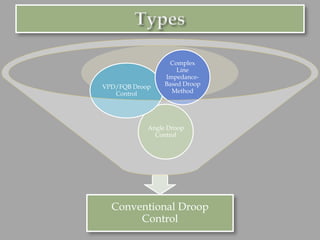
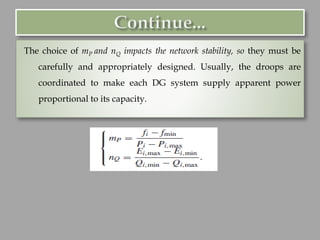
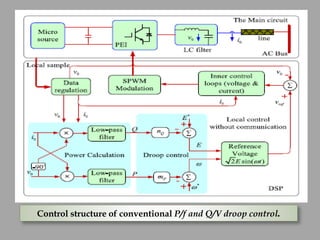
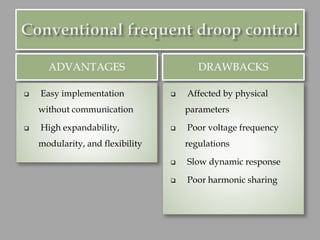
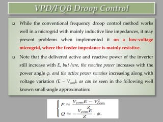
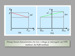
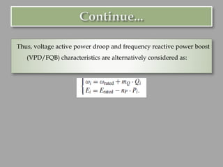
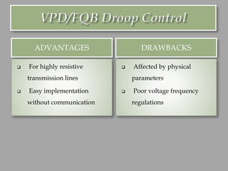
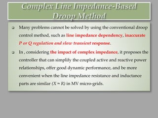
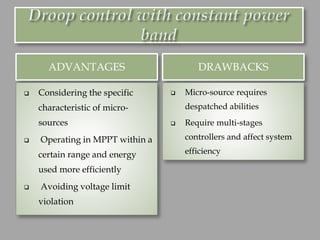
Prof. (Dr.) Pravat Kumar Rout
Sheetal Chandak , Senior Research Fellow CSIR, India
Department of EEE, ITER
Siksha ‘O’ Anusandhan (Deemed to be University),
Bhubaneswar
Class-14: Droop control approach
for power sharing in AC microgrid
❑ Integrated control strategies refer to
hierarchical structures which usually
consist of primary, secondary, and tertiary
control .
❑ The primary control stabilizes the voltage
and frequency and offers plug-and-play
capability for DGs.
❑ The secondary control, as a centralized
controller, compensates for the voltage and
frequency deviations to enhance the power
quality.
❑ Tertiary control considers the optimal
power flowing of the whole microgrids or
interaction with main grid . In addition,
hierarchical control has other special
functions: 1) distributed intelligent
management system ; 2) voltage unbalance
compensation for optimal power quality ;
3) self-healing networks ; 4) smart home
with a cost-effective energy ecosystem; and
5) generation scheduling.
So, the hierarchical
structure of microgrids
can be regarded as an
intelligent, integrated,
and multiagent system.
Power sharing comes
under primary control.
❑ Communication-based control techniques can achieve excellent
voltage regulation and proper power sharing.
❑ Moreover, in contrast to droop controllers, which will be
discussed later, the output voltage amplitude and frequency are
generally close to their ratings without using a secondary
control.
❑ However, these control strategies, which require communication
lines between the modules, result in increased cost of the
system.
❑ The control method requires common synchronization
signals and current sharing modules.
❑ The phase locked loop (PLL) circuit of each module can
ensure the consistency between the frequency and phase of
the output voltage and the synchronization signal.
❑ Also, the current sharing modules can detect the total load,
which define the reference value of the current for each
module. This reference current iref is a fraction of the load
current iload. For N equal modules, iref = iload/N.
ADVANTAGES DRAWBACKS
❑ Good power sharing in
steady state and transients
❑ Constant voltage and
frequency regulation
❑ High bandwidth
communication required
❑ Low reliability and
expandability
❑ The master module regulates the
output voltage and specifies the current
reference of the rest of slave modules.
❑ Then, slave units track the current
reference provided by the master in
order to achieve equal current
distribution.
❑ Inverters do not need any PLL for
synchronization since these units are
communicated with the master units.
However, the system is not redundant
since it presents a single point of failure.
If master unit fails, the whole system
will fail.
ADVANTAGES DRAWBACKS
❑ Recover the output voltage
easily
❑ Good power sharing in
steady state
❑ High current overshoot in
transients
❑ Require high bandwidth
communication
❑ Low redundancy
❑ The distributed control is often applied to parallel converters . The
instantaneous average current sharing is a typically distributed
control for parallel converters.
❑ In this control technique, individual control circuit is used in each
inverter, but no central controller is needed.
❑ Further, average current sharing requires a current sharing bus and
reference synchronization for the voltage. An additional current
control loop is used to enforce each converter to track the same
average reference current, provided by the current sharing bus. When
a defect happen in any module, it can smoothly detach from the
microgrid, and the rest of modules can still operate normally in
parallel.
❑ The distinct feature of the distributed control is that the
information required is not global but adjacent for any units. So,
it only needs lower band-width than the central control method.
Because of dividing the control task among different units, it has
many advantages compared to the droop control.
ADVANTAGES DRAWBACKS
❑ Symmetrical for every
module
❑ Constant voltage and
fundamental power sharing
❑ Require communication bus
❑ Degrade the modularity of
the system
❑ The control strategies that operate without inter-unit
communications for power sharing control are based on droop
concept . Operation without communication links is often essential
to connect remote inverters.
❑ Also, such a system is easier to expand because of the plug-and-
play feature of the modules which allows replacing one unit
without stopping the whole system.
❑ Therefore, communication lines are often avoided especially for
long distances and high-investment cost.
1. Frequency and Voltage Deviations:
In islanding mode, the voltage and frequency of the microgrid are load
dependent. Steeper droop ensures better load sharing, yet results
in larger frequency and voltage deviations, and even may cause
instabilities in the microgrid. This is the inherent trade off between
the frequency and voltage regulation and load sharing accuracy
for the droop method.
2. Harmonic Loads:
The original droop method focuses on fundamental power sharing but
does not take harmonic sharing into account in the case of
nonlinear loads. If it is not coped properly, it would lead to
harmonic circulating currents and poor power quality. Moreover,
the calculation and smoothing of active and reactive power take
some delays, thus it presents a slow dynamic response.
3. Different and Unknown Line Impedances:
The line impedances between the paralleled converters also
affect the power sharing performance. When the line
impedances between the inverters and point of common
coupling are different, it could result in a large circulating
current and low precision of power sharing among
inverters.
4. Fluctuant and Changeable Output Power of DGs:
Another drawback of the original droop method is the poor
performance with renewable energy resources because the output
active power of micro-source is usually fluctuant and changeable.
Conventional Droop
Control
Angle Droop
Control
VPD/FQB Droop
Control
Complex
Line
Impedance-
Based Droop
Method
The controller consist of three control loops:
(1) A power sharing controller is used to generate the magnitude and
frequency of the fundamental output voltage of the inverter
according to the droop characteristics.
(2) A voltage controller is used to synthesize the reference filter
inductor current vector.
(3) A current controller is adopted to generate the command voltage
by a pulse width modulation module.
The basic idea of this control level (also named primary control) is to mimic
the behaviour of a synchronous generator, which is to reduce the frequency
as the active power increases. When the inverter output impedance is highly
inductive, hence the active and reactive powers drawn to the bus can be
expressed as:
where X is the output reactance of an inverter, φ is the phase angle between the
output voltage of the inverter and the voltage of the common bus, and Ei and
V are the amplitude of the output voltage of the inverter and the grid voltage,
respectively.
It can be found that the active power is predominately dependent on
the power angle, while the reactive power mostly depends on the
output voltage amplitude. This principle can be integrated in voltage
source inverters (VSIs) by using the well-known P/Q droop method ,
which can be expressed as:
where i is the index representing each converter, frated and Erated are the nominal
frequency and voltage of the micro-source, respectively, Pi and Qi are the
average active and reactive power, Prated and Qrated are the nominal active and
reactive power, respectively, and mP and nQ are the active and reactive droop
slopes, respectively.
The choice of mP and nQ impacts the network stability, so they must be
carefully and appropriately designed. Usually, the droops are
coordinated to make each DG system supply apparent power
proportional to its capacity.
Control structure of conventional P/f and Q/V droop control.
ADVANTAGES DRAWBACKS
❑ Easy implementation
without communication
❑ High expandability,
modularity, and flexibility
❑ Affected by physical
parameters
❑ Poor voltage frequency
regulations
❑ Slow dynamic response
❑ Poor harmonic sharing
❑ While the conventional frequency droop control method works
well in a microgrid with mainly inductive line impedances, it may
present problems when implemented it on a low-voltage
microgrid, where the feeder impedance is mainly resistive.
❑ Note that the delivered active and reactive power of the inverter
still increase with E, but here, the reactive power increases with the
power angle φ, and the active power remains increasing along with
voltage variation (E − Vcom), as can be seen in the following well
known small-angle approximation:
Droop/boost characteristics for low-voltage ac microgrid. (a) VPD
method. (b) FQB method.
Thus, voltage active power droop and frequency reactive power boost
(VPD/FQB) characteristics are alternatively considered as:
ADVANTAGES DRAWBACKS
❑ For highly resistive
transmission lines
❑ Easy implementation
without communication
❑ Affected by physical
parameters
❑ Poor voltage frequency
regulations
❑ Many problems cannot be solved by using the conventional droop
control method, such as line impedance dependency, inaccurate
P or Q regulation and slow transient response.
❑ In , considering the impact of complex impedance, it proposes the
controller that can simplify the coupled active and reactive power
relationships, offer good dynamic performance, and be more
convenient when the line impedance resistance and inductance
parts are similar (X ≈ R) in MV micro-grids.
In this particular case, the droop functions can be expressed as:
For electric systems with complex impedance, both active and
reactive powers affect the voltage magnitude. Therefore, the droop
characteristics for the proposed P-Q-V droop method is given by:
where Vref is the desired reference value of the PCC voltage, in this case, 1
p.u.; nd and md are the active and reactive power coefficients for the
proposed P-Q-V droop method. Moreover, these droop coefficients are
adjusted online through a lookup table based on the PCC voltage level.
Control algorithm with the proposed P-Q-V droop method
ADVANTAGES DRAWBACKS
❑ Decouples active and
reactive controls
❑ Improved voltage regulation
❑ Line impedances should be
known in advance
In further investigation of the droop concept, some researchers have
proposed power-angle droop control, in which the phase angle of
the distributed source voltage, relative to a system-wide common
timing reference is set. As a result, the power requirement can be
distributed among DGs, similarly as conventional droop does, by
dropping the voltage angle and magnitude:
where Erated and δrated are the rated voltage magnitude and angle of the DG,
respectively, when supplying their rated power levels of Pi,rated and Qi,rated.
Coefficients mP and nQ indicate active and reactive power droop gains.
These values are chosen to meet voltage regulation requirement in the
microgrid. The coefficient values for different DGs are chosen in order to
share the load in proportion to their ratings.
ADVANTAGES DRAWBACKS
❑ Constant frequency
regulation
❑ Requires GPS signals
❑ Poor performance of power
sharing
This control method is another type of P/V control.
❑ The control strategy presents a constant power band control of
islanding ac microgrid, which operates without inter-unit
communication in a fully distributed manner and takes the
specific characteristics of the microgrid into account.
❑ These characteristics include the lack of rotating inertia, resistive
line, and high share of DGs, which are less controllable than
central generators and require optimal power exploitation.
Droop control with constant power band.
The voltage-based droop control strategy consists of a P/V droop
controller which is divided into two droop controllers (Vg/Vdc and P/Vg
droops) and constant-power bands, as illustrated in Fig.
Overall scheme of droop control with constant power band.
ADVANTAGES DRAWBACKS
❑ Considering the specific
characteristic of micro-
sources
❑ Operating in MPPT within a
certain range and energy
used more efficiently
❑ Avoiding voltage limit
violation
❑ Micro-source requires
despatched abilities
❑ Require multi-stages
controllers and affect system
efficiency
 Han, H., Hou, X., Yang, J., Wu, J., Su, M., & Guerrero, J. M. (2015).
Review of power sharing control strategies for islanding operation
of AC microgrids. IEEE Transactions on Smart Grid, 7(1), 200-215.
 Tayab, U. B., Roslan, M. A. B., Hwai, L. J., & Kashif, M. (2017). A
review of droop control techniques for microgrid. Renewable and
Sustainable Energy Reviews, 76, 717-727.
❑ What are the major communication based power sharing control
strategies for islanding operation of AC micro-grids?
❑ What are the major droop characteristics based power sharing
control strategies for islanding operation of AC micro-grids?
❑ What are the major drawbacks of droop characteristics ?

Droop control approach for power sharing in AC microgrid

  • 1.
    Prof. (Dr.) PravatKumar Rout Sheetal Chandak , Senior Research Fellow CSIR, India Department of EEE, ITER Siksha ‘O’ Anusandhan (Deemed to be University), Bhubaneswar Class-14: Droop control approach for power sharing in AC microgrid
  • 2.
    ❑ Integrated controlstrategies refer to hierarchical structures which usually consist of primary, secondary, and tertiary control . ❑ The primary control stabilizes the voltage and frequency and offers plug-and-play capability for DGs. ❑ The secondary control, as a centralized controller, compensates for the voltage and frequency deviations to enhance the power quality. ❑ Tertiary control considers the optimal power flowing of the whole microgrids or interaction with main grid . In addition, hierarchical control has other special functions: 1) distributed intelligent management system ; 2) voltage unbalance compensation for optimal power quality ; 3) self-healing networks ; 4) smart home with a cost-effective energy ecosystem; and 5) generation scheduling. So, the hierarchical structure of microgrids can be regarded as an intelligent, integrated, and multiagent system. Power sharing comes under primary control.
  • 3.
    ❑ Communication-based controltechniques can achieve excellent voltage regulation and proper power sharing. ❑ Moreover, in contrast to droop controllers, which will be discussed later, the output voltage amplitude and frequency are generally close to their ratings without using a secondary control. ❑ However, these control strategies, which require communication lines between the modules, result in increased cost of the system.
  • 5.
    ❑ The controlmethod requires common synchronization signals and current sharing modules. ❑ The phase locked loop (PLL) circuit of each module can ensure the consistency between the frequency and phase of the output voltage and the synchronization signal. ❑ Also, the current sharing modules can detect the total load, which define the reference value of the current for each module. This reference current iref is a fraction of the load current iload. For N equal modules, iref = iload/N.
  • 7.
    ADVANTAGES DRAWBACKS ❑ Goodpower sharing in steady state and transients ❑ Constant voltage and frequency regulation ❑ High bandwidth communication required ❑ Low reliability and expandability
  • 8.
    ❑ The mastermodule regulates the output voltage and specifies the current reference of the rest of slave modules. ❑ Then, slave units track the current reference provided by the master in order to achieve equal current distribution. ❑ Inverters do not need any PLL for synchronization since these units are communicated with the master units. However, the system is not redundant since it presents a single point of failure. If master unit fails, the whole system will fail.
  • 10.
    ADVANTAGES DRAWBACKS ❑ Recoverthe output voltage easily ❑ Good power sharing in steady state ❑ High current overshoot in transients ❑ Require high bandwidth communication ❑ Low redundancy
  • 11.
    ❑ The distributedcontrol is often applied to parallel converters . The instantaneous average current sharing is a typically distributed control for parallel converters. ❑ In this control technique, individual control circuit is used in each inverter, but no central controller is needed. ❑ Further, average current sharing requires a current sharing bus and reference synchronization for the voltage. An additional current control loop is used to enforce each converter to track the same average reference current, provided by the current sharing bus. When a defect happen in any module, it can smoothly detach from the microgrid, and the rest of modules can still operate normally in parallel.
  • 12.
    ❑ The distinctfeature of the distributed control is that the information required is not global but adjacent for any units. So, it only needs lower band-width than the central control method. Because of dividing the control task among different units, it has many advantages compared to the droop control.
  • 14.
    ADVANTAGES DRAWBACKS ❑ Symmetricalfor every module ❑ Constant voltage and fundamental power sharing ❑ Require communication bus ❑ Degrade the modularity of the system
  • 15.
    ❑ The controlstrategies that operate without inter-unit communications for power sharing control are based on droop concept . Operation without communication links is often essential to connect remote inverters. ❑ Also, such a system is easier to expand because of the plug-and- play feature of the modules which allows replacing one unit without stopping the whole system. ❑ Therefore, communication lines are often avoided especially for long distances and high-investment cost.
  • 16.
    1. Frequency andVoltage Deviations: In islanding mode, the voltage and frequency of the microgrid are load dependent. Steeper droop ensures better load sharing, yet results in larger frequency and voltage deviations, and even may cause instabilities in the microgrid. This is the inherent trade off between the frequency and voltage regulation and load sharing accuracy for the droop method.
  • 17.
    2. Harmonic Loads: Theoriginal droop method focuses on fundamental power sharing but does not take harmonic sharing into account in the case of nonlinear loads. If it is not coped properly, it would lead to harmonic circulating currents and poor power quality. Moreover, the calculation and smoothing of active and reactive power take some delays, thus it presents a slow dynamic response.
  • 18.
    3. Different andUnknown Line Impedances: The line impedances between the paralleled converters also affect the power sharing performance. When the line impedances between the inverters and point of common coupling are different, it could result in a large circulating current and low precision of power sharing among inverters.
  • 19.
    4. Fluctuant andChangeable Output Power of DGs: Another drawback of the original droop method is the poor performance with renewable energy resources because the output active power of micro-source is usually fluctuant and changeable.
  • 20.
    Conventional Droop Control Angle Droop Control VPD/FQBDroop Control Complex Line Impedance- Based Droop Method
  • 21.
    The controller consistof three control loops: (1) A power sharing controller is used to generate the magnitude and frequency of the fundamental output voltage of the inverter according to the droop characteristics. (2) A voltage controller is used to synthesize the reference filter inductor current vector. (3) A current controller is adopted to generate the command voltage by a pulse width modulation module.
  • 22.
    The basic ideaof this control level (also named primary control) is to mimic the behaviour of a synchronous generator, which is to reduce the frequency as the active power increases. When the inverter output impedance is highly inductive, hence the active and reactive powers drawn to the bus can be expressed as: where X is the output reactance of an inverter, φ is the phase angle between the output voltage of the inverter and the voltage of the common bus, and Ei and V are the amplitude of the output voltage of the inverter and the grid voltage, respectively.
  • 23.
    It can befound that the active power is predominately dependent on the power angle, while the reactive power mostly depends on the output voltage amplitude. This principle can be integrated in voltage source inverters (VSIs) by using the well-known P/Q droop method , which can be expressed as: where i is the index representing each converter, frated and Erated are the nominal frequency and voltage of the micro-source, respectively, Pi and Qi are the average active and reactive power, Prated and Qrated are the nominal active and reactive power, respectively, and mP and nQ are the active and reactive droop slopes, respectively.
  • 24.
    The choice ofmP and nQ impacts the network stability, so they must be carefully and appropriately designed. Usually, the droops are coordinated to make each DG system supply apparent power proportional to its capacity.
  • 25.
    Control structure ofconventional P/f and Q/V droop control.
  • 26.
    ADVANTAGES DRAWBACKS ❑ Easyimplementation without communication ❑ High expandability, modularity, and flexibility ❑ Affected by physical parameters ❑ Poor voltage frequency regulations ❑ Slow dynamic response ❑ Poor harmonic sharing
  • 27.
    ❑ While theconventional frequency droop control method works well in a microgrid with mainly inductive line impedances, it may present problems when implemented it on a low-voltage microgrid, where the feeder impedance is mainly resistive. ❑ Note that the delivered active and reactive power of the inverter still increase with E, but here, the reactive power increases with the power angle φ, and the active power remains increasing along with voltage variation (E − Vcom), as can be seen in the following well known small-angle approximation:
  • 28.
    Droop/boost characteristics forlow-voltage ac microgrid. (a) VPD method. (b) FQB method.
  • 29.
    Thus, voltage activepower droop and frequency reactive power boost (VPD/FQB) characteristics are alternatively considered as:
  • 30.
    ADVANTAGES DRAWBACKS ❑ Forhighly resistive transmission lines ❑ Easy implementation without communication ❑ Affected by physical parameters ❑ Poor voltage frequency regulations
  • 31.
    ❑ Many problemscannot be solved by using the conventional droop control method, such as line impedance dependency, inaccurate P or Q regulation and slow transient response. ❑ In , considering the impact of complex impedance, it proposes the controller that can simplify the coupled active and reactive power relationships, offer good dynamic performance, and be more convenient when the line impedance resistance and inductance parts are similar (X ≈ R) in MV micro-grids.
  • 32.
    In this particularcase, the droop functions can be expressed as: For electric systems with complex impedance, both active and reactive powers affect the voltage magnitude. Therefore, the droop characteristics for the proposed P-Q-V droop method is given by: where Vref is the desired reference value of the PCC voltage, in this case, 1 p.u.; nd and md are the active and reactive power coefficients for the proposed P-Q-V droop method. Moreover, these droop coefficients are adjusted online through a lookup table based on the PCC voltage level.
  • 33.
    Control algorithm withthe proposed P-Q-V droop method
  • 34.
    ADVANTAGES DRAWBACKS ❑ Decouplesactive and reactive controls ❑ Improved voltage regulation ❑ Line impedances should be known in advance
  • 35.
    In further investigationof the droop concept, some researchers have proposed power-angle droop control, in which the phase angle of the distributed source voltage, relative to a system-wide common timing reference is set. As a result, the power requirement can be distributed among DGs, similarly as conventional droop does, by dropping the voltage angle and magnitude: where Erated and δrated are the rated voltage magnitude and angle of the DG, respectively, when supplying their rated power levels of Pi,rated and Qi,rated. Coefficients mP and nQ indicate active and reactive power droop gains. These values are chosen to meet voltage regulation requirement in the microgrid. The coefficient values for different DGs are chosen in order to share the load in proportion to their ratings.
  • 36.
    ADVANTAGES DRAWBACKS ❑ Constantfrequency regulation ❑ Requires GPS signals ❑ Poor performance of power sharing
  • 37.
    This control methodis another type of P/V control. ❑ The control strategy presents a constant power band control of islanding ac microgrid, which operates without inter-unit communication in a fully distributed manner and takes the specific characteristics of the microgrid into account. ❑ These characteristics include the lack of rotating inertia, resistive line, and high share of DGs, which are less controllable than central generators and require optimal power exploitation.
  • 38.
    Droop control withconstant power band. The voltage-based droop control strategy consists of a P/V droop controller which is divided into two droop controllers (Vg/Vdc and P/Vg droops) and constant-power bands, as illustrated in Fig.
  • 39.
    Overall scheme ofdroop control with constant power band.
  • 40.
    ADVANTAGES DRAWBACKS ❑ Consideringthe specific characteristic of micro- sources ❑ Operating in MPPT within a certain range and energy used more efficiently ❑ Avoiding voltage limit violation ❑ Micro-source requires despatched abilities ❑ Require multi-stages controllers and affect system efficiency
  • 41.
     Han, H.,Hou, X., Yang, J., Wu, J., Su, M., & Guerrero, J. M. (2015). Review of power sharing control strategies for islanding operation of AC microgrids. IEEE Transactions on Smart Grid, 7(1), 200-215.  Tayab, U. B., Roslan, M. A. B., Hwai, L. J., & Kashif, M. (2017). A review of droop control techniques for microgrid. Renewable and Sustainable Energy Reviews, 76, 717-727.
  • 42.
    ❑ What arethe major communication based power sharing control strategies for islanding operation of AC micro-grids? ❑ What are the major droop characteristics based power sharing control strategies for islanding operation of AC micro-grids? ❑ What are the major drawbacks of droop characteristics ?