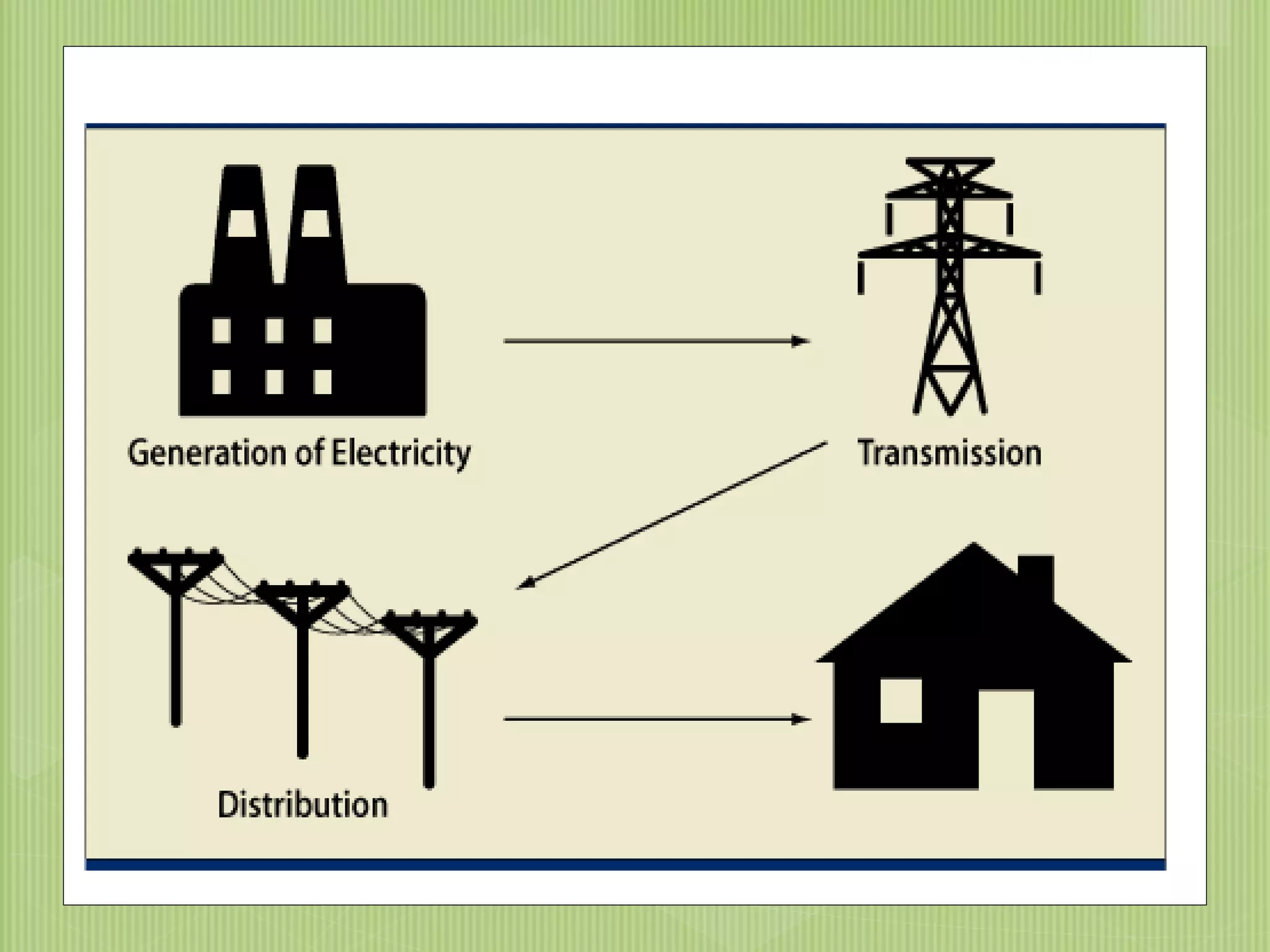
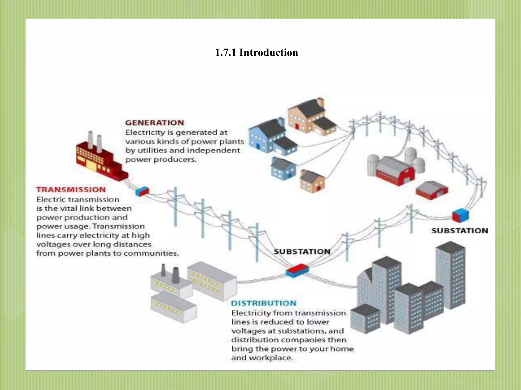
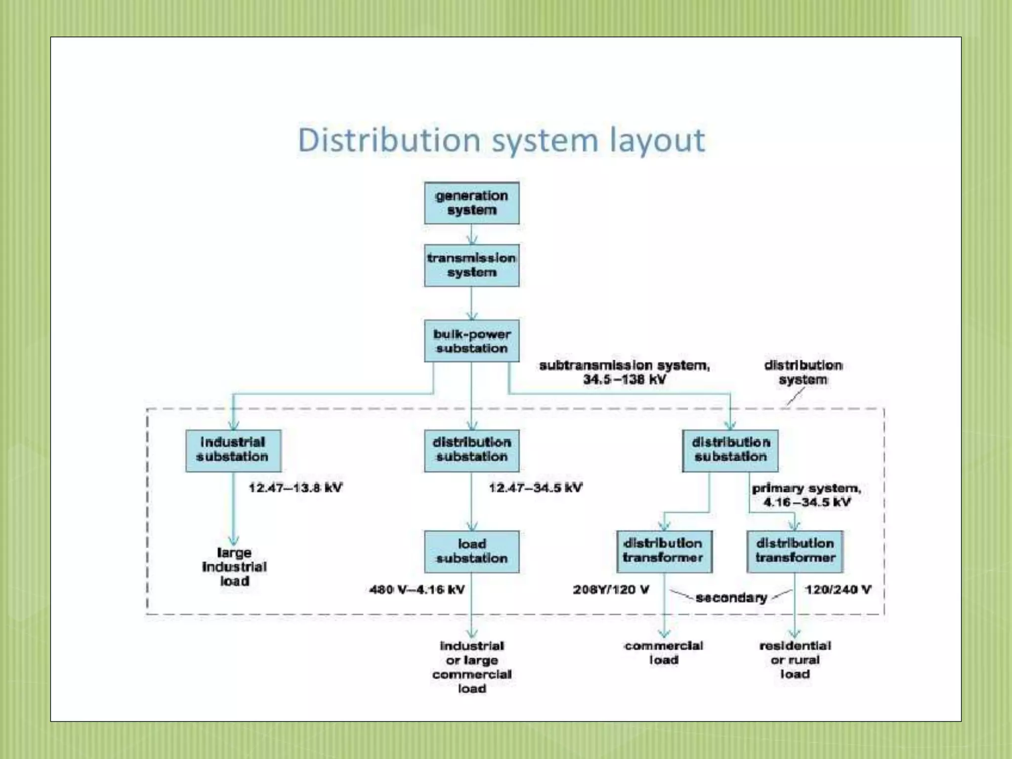
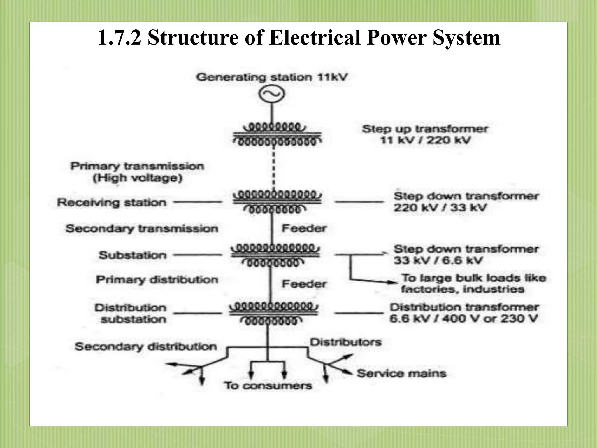
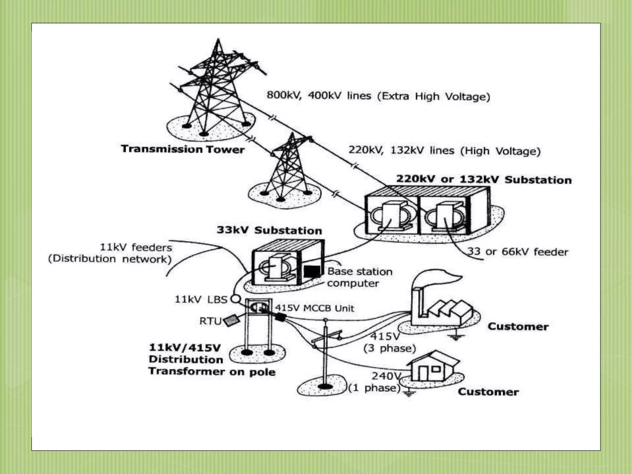
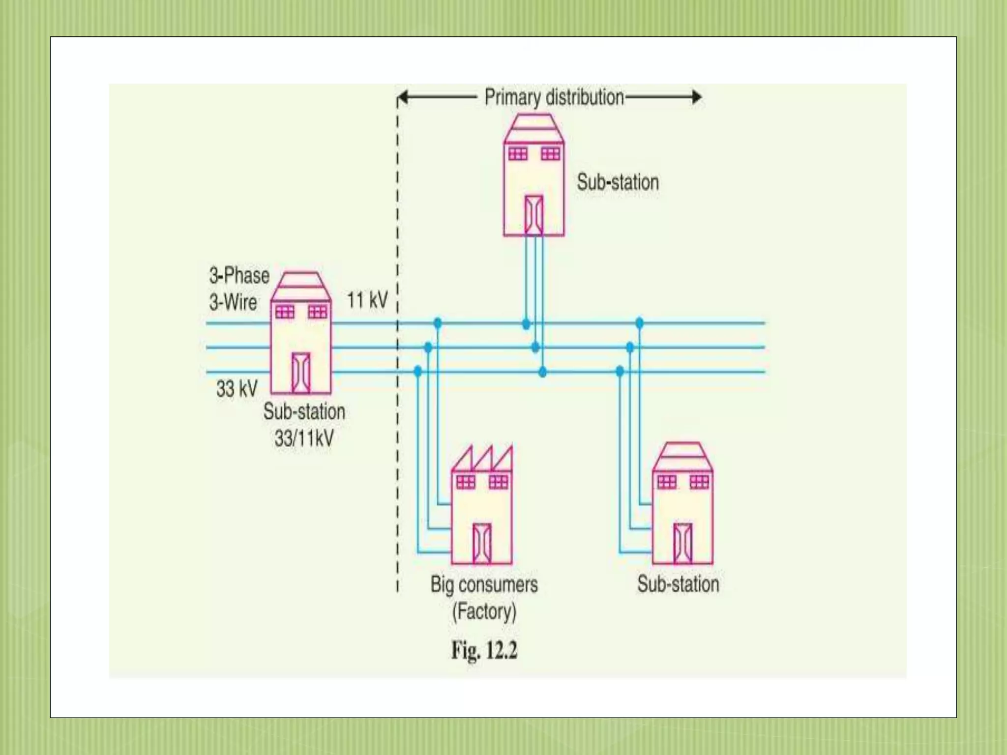
SlideShare a Scribd company logo
1.7 TRANSMISSION AND
DISTRIBUTION OF
ELECTRICAL ENERGY
P. Maria Sheeba
AP/ECE, MZCET
9/20/20151
BY 01,02,03,04,05,06,12604
2 9/20/2015
1.7.1 Introduction
01,02,03,04,05,06,12604
3
9/20/20154
1.7.2 Structure of Electrical Power System
9/20/2015
1.7.3 Distribution System
“The part of power system which distributes
electrical power for local use is known as
DISTRIBUTION SYSTEM.”
This system is the electrical system between the
substation fed by the transmission system and
consumer meter.
Distribution line generally consist of
Feeders
Distributers
Service mains
9/20/2015
FEEDERS DISTRIBUTORS SERVICE MAINS
Distribution
Feeder
 A Feeder is conductor which connects the substation to the
area where power is to be distributed
 Feeder are used to feed the electrical power from the
generating station to the substation
 No tapings are taken from the feeder
 So the current in it remains the same throughout
 Main consideration in the design of feeder is
the Current carrying capacity.
9/20/20158
Distributer
 A distributer is a conductor from which tapings are
taken from pole mounted transformer to the
consumer
 The current through a distributer is not constant
because tapings are taken at various places along its
length
 Voltage drop is main consideration
 Limit of variation is 6% of rated at
consumer
9/20/20159
Service mains
 A service mains is a generally a small cable which
connects the distributer to the consumer ‘s meter.
 The connecting links between the distributor and the
consumer terminals.
9/20/201510
11
9/20/201512
9/20/201513
1.7.4 classification of dc
distribution
 Distribution system is a part of power system,
existing between distribution substations and
consumers.
 It is further classified on the basis of voltage
 Primary distribution system- 11 KV or 6.6 KV or 3.3 KV
 Secondary distribution system- 415 V or 230 V
9/20/201516
Classification Of
Distribution
System:It can be classified under different considerations as;
1. Type Of Current:
a) AC Distribution System
b) DC Distribution System
2. Type Of Construction:
a) Overhead System
b) Underground System
9/20/201517
3. Type Of Service:
a) General Lighting & Power
b) Industrial Power
c) Railway
d) Streetlight etc
c) Interconnected Distribution System
4. Number Of Wires:
a) Two Wire
b) Three Wire
c) Four Wire
5. Scheme Of Connection:
a) Radial Distribution System
b) Ring or Loop Distribution System
9/20/201518
Ac distribution
 A.c. distribution system is the electrical system
between the step-down substation fed by the
transmission system and the consumers’ meters. The
a.c. distribution
system is classified into
 ( i) primary distribution system and
 ( ii) secondary distribution system.
9/20/201519
1.7.5 Primary distribution system
 voltages somewhat higher than general utilisation and
handles large blocks of electrical energy than the average
low-voltage consumer uses.
 Commonly used primary distribution voltage 11KV, 6.6 KV,3.3
KV.
 Electric power from the generating station is transmitted at
high voltage to the substation located in or near the city.
 At this substation, voltage is stepped down to 11 kV with the
help of step-down transformer.
 Power is supplied to various substations for distribution or
to big consumers at this voltage.
 This forms the high voltage distribution or primary distribution.
9/20/201520
9/20/20121
1.7.6 Secondary distribution system
 It is that part of a.c. distribution system which includes
the range of voltages at which the ultimate consumer
utilizes the electrical energy delivered to him.
 The secondary distribution employs 400/230 V, 3-
phase, 4-wire system.
22
23
D.C. Distribution
 D.c. supply is required for the operation of variable speed
machinery ( i.e., d.c. motors), for electro-chemical work and
for congested areas where storage battery reserves are
necessary.
 For this purpose, a.c. power is converted into
d.c. power at the substation by using converting machinery
e.g., mercury arc rectifiers, and motor-generator sets.
24
Type of DC distributor
 The dc supply from the substation may be
obtained in form of
 ( i) 2-wire or
 ( ii) 3-wire for distribution.
25
2 wire 3 wire
9/20/201526
27
 Two outer and a middle or neutral wire is earthed at the
s/s.
 Voltage between the outer is twice the voltage
between either outer and neutral wire.
 Advantage – available two voltage at the consumer
terminal.
 Loads requiring high voltage connected across the
outers.
 Lamps and heating circuits requiring less voltage are
connected between either outer and neutral.
Method of obtaining 3 wire D.c
system
 Two generator method.
 3-wire D.c. generator.
 Balancer set
9/20/201528
Two generator method
29
Two generator method
 D.c generator G1 and G2 are connected in series and
the neutral is obtained from the common point btwn
generator
 G1 supplies a I1, G2 supplies a I2
 Difference of load current on both side (I1-I2) flow
through the neutral wire.
 Disad.:two separate generator are required.
9/20/201530
3-wire D.c. generator.
9/20/201531
3-wire D.c. generator.
 Consist of a standard 2 wire machine with one or
two coils of high reactance and low resistance that
connected to opposite points of the armature
winding.
 Neutral wire is obtained from common
point.
9/20/201532
Connection schemes of
distribution system
 Radial system
 Ring main system
 Interconnected system
9/20/201533
Radial Distribution
System:
9/20/2015
 separate feeders radiate from a single substation and feed the
distributors at one end only.
 Only one path is connected between each customer and
substation.
 Electrical power flows along a single path.
 If interrupted, results in complete loss of power to the customer.
.
34
Advantages:
 Low cost .
 Simple planning.
Disadvantages :
 The radial system is employed only when power is
generated at low voltage and the substation is located at
the centre of the load.
 Distributor nearer to feeding end is heavily loaded.
 Consumers at far end of feeder would be subjected to
serious
voltage fluctuations
34
9/20/21535
9/20/201536
Ring or Loop Distribution
System: It consists of two or more paths between
power sources and the customer.
 The loop circuit starts from the substation bus-bars,
makes a loop through the area to be served, and returns
to the substation
Advantages:
 Less conductor material is required.
 Less voltage fluctuations.
 More reliable.
Disadvantages:
 It is difficult to design as compared to the
design of radial system.
37 26/1/2018
38
9/20/201540
1.7.7 D.C. Distribution
 D.c. supply is required for the operation of variable
speed machinery ( i.e., d.c. motors),
 for electro-chemical work and for congested areas
where storage battery reserves are necessary.
 For this purpose, a.c. power is converted into d.c. power
at the substation by using converting machinery e.g.,
mercury arc rectifiers, rotary converters and motor-
generator sets. The d.c. supply from the substation may
be obtained in the form of
9/20/201543
DC
Distribution: Voltage drop along distributor is considered as a
main factor while designing a distributor.
 It depends upon the nature of load and also on
feeding, whether it is fed at one or both ends.
According to loading, a distributor can be classified as:
i. Fed at one end.
ii. Fed at both ends. a). With equal voltages.
b). With unequal voltages.
iii. Fed at centre.
Ring mains.
9/20/2015
DC Distribution Feed at one end
9/20/2015
 a) The current in the various sections of the
distributor away from feeding point goes on decreasing.
Thus current in section AC is more than the current in
section CD and current in section CD is more than the
current in section DE.
 (b) The voltage across the loads away from the
feeding point goes on decreasing. Thus in Fig. 13.1, the
minimum voltage occurs at the load point E.
 (c) In case a fault occurs on any section of the
distributor, the whole distributor will have to be
disconnected from the supply mains. Therefore,
continuity of supply is interrupted
Distributor fed at center
47
 In this type of feeding the distributor is connected to the supply mains
at both ends and loads are tapped off at different points along the length
of the distributor.
The voltage at the feeding points may or may not be equal. distributor
A B fed at the ends A and B and loads of I1, I2 and I3 tapped off at points
C respectively.
 Here, the load voltage goes on decreasing as we move away from one
feeding point say A , reaches minimum value and then again starts rising
and reaches maximum value when we reach the other feeding point B.
 The minimum voltage occurs at some load point and is never fixed. It
is shifted with the variation of load on different sections of the
distributor.
Advantages
 (a) If a fault occurs on any feeding point of the
distributor, the continuity of supply is main-tained from
the other feeding point.
 (b) In case of fault on any section of the distributor, the
continuity of supply is maintained from the other feeding
point.
 (C)The area of X-section required for a doubly fed
distributor is much less than that of a singly fed
distributor.
9/20/201549
Ring
Distributor
9/20/201550
9/20/201551
 In this type of feeding, the centre of the distributor is
connected to the supply mains as shown in Fig.
 It is equivalent to two singly fed distributors,
each distributor having a common feeding point and
length equal to half of the total length
Overall discussion
 From this lesson you are able to understand
the transmission and distribution system.
We have also seen about types of
distributors across the system.

More Related Content

What's hot

33/11 KV SUBSTATION
33/11 KV SUBSTATION33/11 KV SUBSTATION
33/11 KV SUBSTATION
k,l polytechnic roorkee
 
Distribution System
Distribution SystemDistribution System
Distribution System
Kupusaami Anbumani
 
SUB-STATION DESIGN AND PROTECTION (AN OVERVIEW)
SUB-STATION DESIGN AND PROTECTION  (AN OVERVIEW)SUB-STATION DESIGN AND PROTECTION  (AN OVERVIEW)
SUB-STATION DESIGN AND PROTECTION (AN OVERVIEW)
Ameh Messiah Edache
 
TDU Unit 03 Distribution Systems
TDU Unit  03 Distribution SystemsTDU Unit  03 Distribution Systems
TDU Unit 03 Distribution Systems
PremanandDesai
 
Electric power transmission full explanation and presentation
Electric power transmission full explanation and presentationElectric power transmission full explanation and presentation
Electric power transmission full explanation and presentation
Rakesh Gurjar
 
Types Of Substations
Types Of SubstationsTypes Of Substations
Types Of Substations
sapna186
 
Transmission & distribution of electrical power
Transmission & distribution of electrical powerTransmission & distribution of electrical power
Transmission & distribution of electrical power
priyanka1432
 
Distribution systems
Distribution systemsDistribution systems
Distribution systems
SURAJ PRASAD
 
400kv sub-station-final-ppt-by-mohit
400kv sub-station-final-ppt-by-mohit400kv sub-station-final-ppt-by-mohit
400kv sub-station-final-ppt-by-mohitMohit Awasthi
 
Electrical bus bar and its types
Electrical bus bar and its typesElectrical bus bar and its types
Electrical bus bar and its types
Jay Ranvir
 
Shashikdoc
ShashikdocShashikdoc
Shashikdoc
Shashik132
 
Report on industrial summer training on 220 kv substation
Report  on industrial summer training on 220 kv substationReport  on industrial summer training on 220 kv substation
Report on industrial summer training on 220 kv substation
Ashutosh Srivastava
 
220 kv Sub-station Summer Training ppt
220 kv Sub-station Summer Training ppt220 kv Sub-station Summer Training ppt
220 kv Sub-station Summer Training ppt
Shubham Patel
 
Presentation on substations
Presentation on substationsPresentation on substations
Presentation on substations
vishalgohel12195
 
Design of substation
Design of substationDesign of substation
Design of substation
SayanSarkar55
 
Overhead line work ppt
Overhead line work pptOverhead line work ppt
Overhead line work ppt
Demsew Mitiku
 
PPt on 220 kV substation
PPt on 220 kV substationPPt on 220 kV substation
PPt on 220 kV substationIshank Ranjan
 
Substation Training presentation
Substation Training presentationSubstation Training presentation
Substation Training presentation
Kamal Mittal
 
**Lightning Arrester Presentation**
**Lightning Arrester Presentation****Lightning Arrester Presentation**
**Lightning Arrester Presentation**SKPAMB
 

What's hot (20)

33/11 KV SUBSTATION
33/11 KV SUBSTATION33/11 KV SUBSTATION
33/11 KV SUBSTATION
 
Distribution System
Distribution SystemDistribution System
Distribution System
 
SUB-STATION DESIGN AND PROTECTION (AN OVERVIEW)
SUB-STATION DESIGN AND PROTECTION  (AN OVERVIEW)SUB-STATION DESIGN AND PROTECTION  (AN OVERVIEW)
SUB-STATION DESIGN AND PROTECTION (AN OVERVIEW)
 
TDU Unit 03 Distribution Systems
TDU Unit  03 Distribution SystemsTDU Unit  03 Distribution Systems
TDU Unit 03 Distribution Systems
 
Electric power transmission full explanation and presentation
Electric power transmission full explanation and presentationElectric power transmission full explanation and presentation
Electric power transmission full explanation and presentation
 
132 kv
132 kv132 kv
132 kv
 
Types Of Substations
Types Of SubstationsTypes Of Substations
Types Of Substations
 
Transmission & distribution of electrical power
Transmission & distribution of electrical powerTransmission & distribution of electrical power
Transmission & distribution of electrical power
 
Distribution systems
Distribution systemsDistribution systems
Distribution systems
 
400kv sub-station-final-ppt-by-mohit
400kv sub-station-final-ppt-by-mohit400kv sub-station-final-ppt-by-mohit
400kv sub-station-final-ppt-by-mohit
 
Electrical bus bar and its types
Electrical bus bar and its typesElectrical bus bar and its types
Electrical bus bar and its types
 
Shashikdoc
ShashikdocShashikdoc
Shashikdoc
 
Report on industrial summer training on 220 kv substation
Report  on industrial summer training on 220 kv substationReport  on industrial summer training on 220 kv substation
Report on industrial summer training on 220 kv substation
 
220 kv Sub-station Summer Training ppt
220 kv Sub-station Summer Training ppt220 kv Sub-station Summer Training ppt
220 kv Sub-station Summer Training ppt
 
Presentation on substations
Presentation on substationsPresentation on substations
Presentation on substations
 
Design of substation
Design of substationDesign of substation
Design of substation
 
Overhead line work ppt
Overhead line work pptOverhead line work ppt
Overhead line work ppt
 
PPt on 220 kV substation
PPt on 220 kV substationPPt on 220 kV substation
PPt on 220 kV substation
 
Substation Training presentation
Substation Training presentationSubstation Training presentation
Substation Training presentation
 
**Lightning Arrester Presentation**
**Lightning Arrester Presentation****Lightning Arrester Presentation**
**Lightning Arrester Presentation**
 

Similar to 1.7 transmission and distribution system of electrical energy

Module 05 - Distribution Systems Overview (1).pptx
Module 05 - Distribution Systems Overview (1).pptxModule 05 - Distribution Systems Overview (1).pptx
Module 05 - Distribution Systems Overview (1).pptx
Zahid Yousaf
 
Distribution System od power system engi
Distribution System od power system engiDistribution System od power system engi
Distribution System od power system engi
Vatsalkumarpatel
 
Classification of distribution systems
Classification of distribution systemsClassification of distribution systems
Classification of distribution systems
Santhi Anumula
 
electricaldistributionsystemelectricaldistributionsystem.pptx
electricaldistributionsystemelectricaldistributionsystem.pptxelectricaldistributionsystemelectricaldistributionsystem.pptx
electricaldistributionsystemelectricaldistributionsystem.pptx
akashsharma3782
 
Distibution.pptx
Distibution.pptxDistibution.pptx
Distibution.pptx
ManidharThula1
 
Electrical power distribution and utilization
Electrical power distribution and utilizationElectrical power distribution and utilization
Electrical power distribution and utilization
MuhammadAliImran11
 
Lab manual psd v sem experiment no 3
Lab manual psd v sem experiment no 3Lab manual psd v sem experiment no 3
Lab manual psd v sem experiment no 3
Sachin Airan
 
AC DISTRIBUTION - ELECTRICAL POWER SYSTEM
AC DISTRIBUTION - ELECTRICAL POWER SYSTEMAC DISTRIBUTION - ELECTRICAL POWER SYSTEM
AC DISTRIBUTION - ELECTRICAL POWER SYSTEM
Dr. Gudipudi Nageswara Rao
 
Distribution System-2 in power system Engin
Distribution System-2 in power system EnginDistribution System-2 in power system Engin
Distribution System-2 in power system Engin
Vatsalkumarpatel
 
Principles of Power Systems V.K Mehta Complete Book - Chapter 7
Principles of Power Systems V.K Mehta Complete Book - Chapter 7Principles of Power Systems V.K Mehta Complete Book - Chapter 7
Principles of Power Systems V.K Mehta Complete Book - Chapter 7
Power System Operation
 
220v gss working modelFinal report
220v gss working modelFinal report220v gss working modelFinal report
220v gss working modelFinal report
giriraj bairwa
 
ch_introduction to power1 part 1_ppt[1].pdf
ch_introduction to power1 part 1_ppt[1].pdfch_introduction to power1 part 1_ppt[1].pdf
ch_introduction to power1 part 1_ppt[1].pdf
abelchernet1627
 
Transmission & Distribution of Electric Power .pptx
Transmission & Distribution of Electric Power .pptxTransmission & Distribution of Electric Power .pptx
Transmission & Distribution of Electric Power .pptx
MdMeshkatHasan213331
 
Simulation of different power transmission systems and their capacity of redu...
Simulation of different power transmission systems and their capacity of redu...Simulation of different power transmission systems and their capacity of redu...
Simulation of different power transmission systems and their capacity of redu...
eSAT Publishing House
 
Distribution System Voltage Drop and Power Loss Calculation
Distribution System Voltage Drop and Power Loss CalculationDistribution System Voltage Drop and Power Loss Calculation
Distribution System Voltage Drop and Power Loss Calculation
Ameen San
 
LEC #01 INTRODUCTION to power distribution system
LEC #01 INTRODUCTION to power distribution systemLEC #01 INTRODUCTION to power distribution system
LEC #01 INTRODUCTION to power distribution system
MuhammadAliImran11
 
Lmaac transmissionand distribution
Lmaac transmissionand distributionLmaac transmissionand distribution
Lmaac transmissionand distribution
GHSKassKoronaMardan
 
146686534 ee-410-lab1-fall10-1305411901
146686534 ee-410-lab1-fall10-1305411901146686534 ee-410-lab1-fall10-1305411901
146686534 ee-410-lab1-fall10-1305411901
homeworkping3
 
HVDC System
HVDC SystemHVDC System
HVDC System
SANTOSH GADEKAR
 
TDU - Unit 01 Transmission system
TDU - Unit  01 Transmission system TDU - Unit  01 Transmission system
TDU - Unit 01 Transmission system
PremanandDesai
 

Similar to 1.7 transmission and distribution system of electrical energy (20)

Module 05 - Distribution Systems Overview (1).pptx
Module 05 - Distribution Systems Overview (1).pptxModule 05 - Distribution Systems Overview (1).pptx
Module 05 - Distribution Systems Overview (1).pptx
 
Distribution System od power system engi
Distribution System od power system engiDistribution System od power system engi
Distribution System od power system engi
 
Classification of distribution systems
Classification of distribution systemsClassification of distribution systems
Classification of distribution systems
 
electricaldistributionsystemelectricaldistributionsystem.pptx
electricaldistributionsystemelectricaldistributionsystem.pptxelectricaldistributionsystemelectricaldistributionsystem.pptx
electricaldistributionsystemelectricaldistributionsystem.pptx
 
Distibution.pptx
Distibution.pptxDistibution.pptx
Distibution.pptx
 
Electrical power distribution and utilization
Electrical power distribution and utilizationElectrical power distribution and utilization
Electrical power distribution and utilization
 
Lab manual psd v sem experiment no 3
Lab manual psd v sem experiment no 3Lab manual psd v sem experiment no 3
Lab manual psd v sem experiment no 3
 
AC DISTRIBUTION - ELECTRICAL POWER SYSTEM
AC DISTRIBUTION - ELECTRICAL POWER SYSTEMAC DISTRIBUTION - ELECTRICAL POWER SYSTEM
AC DISTRIBUTION - ELECTRICAL POWER SYSTEM
 
Distribution System-2 in power system Engin
Distribution System-2 in power system EnginDistribution System-2 in power system Engin
Distribution System-2 in power system Engin
 
Principles of Power Systems V.K Mehta Complete Book - Chapter 7
Principles of Power Systems V.K Mehta Complete Book - Chapter 7Principles of Power Systems V.K Mehta Complete Book - Chapter 7
Principles of Power Systems V.K Mehta Complete Book - Chapter 7
 
220v gss working modelFinal report
220v gss working modelFinal report220v gss working modelFinal report
220v gss working modelFinal report
 
ch_introduction to power1 part 1_ppt[1].pdf
ch_introduction to power1 part 1_ppt[1].pdfch_introduction to power1 part 1_ppt[1].pdf
ch_introduction to power1 part 1_ppt[1].pdf
 
Transmission & Distribution of Electric Power .pptx
Transmission & Distribution of Electric Power .pptxTransmission & Distribution of Electric Power .pptx
Transmission & Distribution of Electric Power .pptx
 
Simulation of different power transmission systems and their capacity of redu...
Simulation of different power transmission systems and their capacity of redu...Simulation of different power transmission systems and their capacity of redu...
Simulation of different power transmission systems and their capacity of redu...
 
Distribution System Voltage Drop and Power Loss Calculation
Distribution System Voltage Drop and Power Loss CalculationDistribution System Voltage Drop and Power Loss Calculation
Distribution System Voltage Drop and Power Loss Calculation
 
LEC #01 INTRODUCTION to power distribution system
LEC #01 INTRODUCTION to power distribution systemLEC #01 INTRODUCTION to power distribution system
LEC #01 INTRODUCTION to power distribution system
 
Lmaac transmissionand distribution
Lmaac transmissionand distributionLmaac transmissionand distribution
Lmaac transmissionand distribution
 
146686534 ee-410-lab1-fall10-1305411901
146686534 ee-410-lab1-fall10-1305411901146686534 ee-410-lab1-fall10-1305411901
146686534 ee-410-lab1-fall10-1305411901
 
HVDC System
HVDC SystemHVDC System
HVDC System
 
TDU - Unit 01 Transmission system
TDU - Unit  01 Transmission system TDU - Unit  01 Transmission system
TDU - Unit 01 Transmission system
 

More from W3Edify

class gd.pptx
class gd.pptxclass gd.pptx
class gd.pptx
W3Edify
 
P.maria sheeba 15 mco010
P.maria sheeba 15 mco010P.maria sheeba 15 mco010
P.maria sheeba 15 mco010
W3Edify
 
Symposium
SymposiumSymposium
Symposium
W3Edify
 
Unit 1
Unit 1Unit 1
Unit 1
W3Edify
 
Beie unit - 5
Beie unit - 5Beie unit - 5
Beie unit - 5
W3Edify
 
Unit 4
Unit 4Unit 4
Unit 4
W3Edify
 
Beie unit 2
Beie unit 2Beie unit 2
Beie unit 2
W3Edify
 
2.9
2.92.9
2.9
W3Edify
 
2.5
2.52.5
2.5
W3Edify
 
2.4 & 2.7
2.4 & 2.72.4 & 2.7
2.4 & 2.7
W3Edify
 
2.3, 2.8, 2.10, 2.11
2.3, 2.8, 2.10, 2.112.3, 2.8, 2.10, 2.11
2.3, 2.8, 2.10, 2.11
W3Edify
 
2.2
2.22.2
2.2
W3Edify
 
2.1
2.12.1
2.1
W3Edify
 
Beie unit-3
Beie  unit-3Beie  unit-3
Beie unit-3
W3Edify
 
3.1,3.2,3.3
3.1,3.2,3.33.1,3.2,3.3
3.1,3.2,3.3
W3Edify
 
Transformer introduction
Transformer   introductionTransformer   introduction
Transformer introduction
W3Edify
 
Three phase transformers
Three phase transformersThree phase transformers
Three phase transformers
W3Edify
 
Transformer ratio & equivalent circuit of transformer
Transformer ratio & equivalent circuit of transformerTransformer ratio & equivalent circuit of transformer
Transformer ratio & equivalent circuit of transformer
W3Edify
 
Ideal transformer
Ideal transformerIdeal transformer
Ideal transformer
W3Edify
 
1.11 power factor improvement
1.11 power factor improvement1.11 power factor improvement
1.11 power factor improvement
W3Edify
 

More from W3Edify (20)

class gd.pptx
class gd.pptxclass gd.pptx
class gd.pptx
 
P.maria sheeba 15 mco010
P.maria sheeba 15 mco010P.maria sheeba 15 mco010
P.maria sheeba 15 mco010
 
Symposium
SymposiumSymposium
Symposium
 
Unit 1
Unit 1Unit 1
Unit 1
 
Beie unit - 5
Beie unit - 5Beie unit - 5
Beie unit - 5
 
Unit 4
Unit 4Unit 4
Unit 4
 
Beie unit 2
Beie unit 2Beie unit 2
Beie unit 2
 
2.9
2.92.9
2.9
 
2.5
2.52.5
2.5
 
2.4 & 2.7
2.4 & 2.72.4 & 2.7
2.4 & 2.7
 
2.3, 2.8, 2.10, 2.11
2.3, 2.8, 2.10, 2.112.3, 2.8, 2.10, 2.11
2.3, 2.8, 2.10, 2.11
 
2.2
2.22.2
2.2
 
2.1
2.12.1
2.1
 
Beie unit-3
Beie  unit-3Beie  unit-3
Beie unit-3
 
3.1,3.2,3.3
3.1,3.2,3.33.1,3.2,3.3
3.1,3.2,3.3
 
Transformer introduction
Transformer   introductionTransformer   introduction
Transformer introduction
 
Three phase transformers
Three phase transformersThree phase transformers
Three phase transformers
 
Transformer ratio & equivalent circuit of transformer
Transformer ratio & equivalent circuit of transformerTransformer ratio & equivalent circuit of transformer
Transformer ratio & equivalent circuit of transformer
 
Ideal transformer
Ideal transformerIdeal transformer
Ideal transformer
 
1.11 power factor improvement
1.11 power factor improvement1.11 power factor improvement
1.11 power factor improvement
 

Recently uploaded

Courier management system project report.pdf
Courier management system project report.pdfCourier management system project report.pdf
Courier management system project report.pdf
Kamal Acharya
 
H.Seo, ICLR 2024, MLILAB, KAIST AI.pdf
H.Seo,  ICLR 2024, MLILAB,  KAIST AI.pdfH.Seo,  ICLR 2024, MLILAB,  KAIST AI.pdf
H.Seo, ICLR 2024, MLILAB, KAIST AI.pdf
MLILAB
 
COLLEGE BUS MANAGEMENT SYSTEM PROJECT REPORT.pdf
COLLEGE BUS MANAGEMENT SYSTEM PROJECT REPORT.pdfCOLLEGE BUS MANAGEMENT SYSTEM PROJECT REPORT.pdf
COLLEGE BUS MANAGEMENT SYSTEM PROJECT REPORT.pdf
Kamal Acharya
 
ASME IX(9) 2007 Full Version .pdf
ASME IX(9)  2007 Full Version       .pdfASME IX(9)  2007 Full Version       .pdf
ASME IX(9) 2007 Full Version .pdf
AhmedHussein950959
 
addressing modes in computer architecture
addressing modes  in computer architectureaddressing modes  in computer architecture
addressing modes in computer architecture
ShahidSultan24
 
Railway Signalling Principles Edition 3.pdf
Railway Signalling Principles Edition 3.pdfRailway Signalling Principles Edition 3.pdf
Railway Signalling Principles Edition 3.pdf
TeeVichai
 
block diagram and signal flow graph representation
block diagram and signal flow graph representationblock diagram and signal flow graph representation
block diagram and signal flow graph representation
Divya Somashekar
 
Pile Foundation by Venkatesh Taduvai (Sub Geotechnical Engineering II)-conver...
Pile Foundation by Venkatesh Taduvai (Sub Geotechnical Engineering II)-conver...Pile Foundation by Venkatesh Taduvai (Sub Geotechnical Engineering II)-conver...
Pile Foundation by Venkatesh Taduvai (Sub Geotechnical Engineering II)-conver...
AJAYKUMARPUND1
 
Standard Reomte Control Interface - Neometrix
Standard Reomte Control Interface - NeometrixStandard Reomte Control Interface - Neometrix
Standard Reomte Control Interface - Neometrix
Neometrix_Engineering_Pvt_Ltd
 
CME397 Surface Engineering- Professional Elective
CME397 Surface Engineering- Professional ElectiveCME397 Surface Engineering- Professional Elective
CME397 Surface Engineering- Professional Elective
karthi keyan
 
Quality defects in TMT Bars, Possible causes and Potential Solutions.
Quality defects in TMT Bars, Possible causes and Potential Solutions.Quality defects in TMT Bars, Possible causes and Potential Solutions.
Quality defects in TMT Bars, Possible causes and Potential Solutions.
PrashantGoswami42
 
Nuclear Power Economics and Structuring 2024
Nuclear Power Economics and Structuring 2024Nuclear Power Economics and Structuring 2024
Nuclear Power Economics and Structuring 2024
Massimo Talia
 
TECHNICAL TRAINING MANUAL GENERAL FAMILIARIZATION COURSE
TECHNICAL TRAINING MANUAL   GENERAL FAMILIARIZATION COURSETECHNICAL TRAINING MANUAL   GENERAL FAMILIARIZATION COURSE
TECHNICAL TRAINING MANUAL GENERAL FAMILIARIZATION COURSE
DuvanRamosGarzon1
 
Cosmetic shop management system project report.pdf
Cosmetic shop management system project report.pdfCosmetic shop management system project report.pdf
Cosmetic shop management system project report.pdf
Kamal Acharya
 
Final project report on grocery store management system..pdf
Final project report on grocery store management system..pdfFinal project report on grocery store management system..pdf
Final project report on grocery store management system..pdf
Kamal Acharya
 
Democratizing Fuzzing at Scale by Abhishek Arya
Democratizing Fuzzing at Scale by Abhishek AryaDemocratizing Fuzzing at Scale by Abhishek Arya
Democratizing Fuzzing at Scale by Abhishek Arya
abh.arya
 
Vaccine management system project report documentation..pdf
Vaccine management system project report documentation..pdfVaccine management system project report documentation..pdf
Vaccine management system project report documentation..pdf
Kamal Acharya
 
Forklift Classes Overview by Intella Parts
Forklift Classes Overview by Intella PartsForklift Classes Overview by Intella Parts
Forklift Classes Overview by Intella Parts
Intella Parts
 
Architectural Portfolio Sean Lockwood
Architectural Portfolio Sean LockwoodArchitectural Portfolio Sean Lockwood
Architectural Portfolio Sean Lockwood
seandesed
 
Automobile Management System Project Report.pdf
Automobile Management System Project Report.pdfAutomobile Management System Project Report.pdf
Automobile Management System Project Report.pdf
Kamal Acharya
 

Recently uploaded (20)

Courier management system project report.pdf
Courier management system project report.pdfCourier management system project report.pdf
Courier management system project report.pdf
 
H.Seo, ICLR 2024, MLILAB, KAIST AI.pdf
H.Seo,  ICLR 2024, MLILAB,  KAIST AI.pdfH.Seo,  ICLR 2024, MLILAB,  KAIST AI.pdf
H.Seo, ICLR 2024, MLILAB, KAIST AI.pdf
 
COLLEGE BUS MANAGEMENT SYSTEM PROJECT REPORT.pdf
COLLEGE BUS MANAGEMENT SYSTEM PROJECT REPORT.pdfCOLLEGE BUS MANAGEMENT SYSTEM PROJECT REPORT.pdf
COLLEGE BUS MANAGEMENT SYSTEM PROJECT REPORT.pdf
 
ASME IX(9) 2007 Full Version .pdf
ASME IX(9)  2007 Full Version       .pdfASME IX(9)  2007 Full Version       .pdf
ASME IX(9) 2007 Full Version .pdf
 
addressing modes in computer architecture
addressing modes  in computer architectureaddressing modes  in computer architecture
addressing modes in computer architecture
 
Railway Signalling Principles Edition 3.pdf
Railway Signalling Principles Edition 3.pdfRailway Signalling Principles Edition 3.pdf
Railway Signalling Principles Edition 3.pdf
 
block diagram and signal flow graph representation
block diagram and signal flow graph representationblock diagram and signal flow graph representation
block diagram and signal flow graph representation
 
Pile Foundation by Venkatesh Taduvai (Sub Geotechnical Engineering II)-conver...
Pile Foundation by Venkatesh Taduvai (Sub Geotechnical Engineering II)-conver...Pile Foundation by Venkatesh Taduvai (Sub Geotechnical Engineering II)-conver...
Pile Foundation by Venkatesh Taduvai (Sub Geotechnical Engineering II)-conver...
 
Standard Reomte Control Interface - Neometrix
Standard Reomte Control Interface - NeometrixStandard Reomte Control Interface - Neometrix
Standard Reomte Control Interface - Neometrix
 
CME397 Surface Engineering- Professional Elective
CME397 Surface Engineering- Professional ElectiveCME397 Surface Engineering- Professional Elective
CME397 Surface Engineering- Professional Elective
 
Quality defects in TMT Bars, Possible causes and Potential Solutions.
Quality defects in TMT Bars, Possible causes and Potential Solutions.Quality defects in TMT Bars, Possible causes and Potential Solutions.
Quality defects in TMT Bars, Possible causes and Potential Solutions.
 
Nuclear Power Economics and Structuring 2024
Nuclear Power Economics and Structuring 2024Nuclear Power Economics and Structuring 2024
Nuclear Power Economics and Structuring 2024
 
TECHNICAL TRAINING MANUAL GENERAL FAMILIARIZATION COURSE
TECHNICAL TRAINING MANUAL   GENERAL FAMILIARIZATION COURSETECHNICAL TRAINING MANUAL   GENERAL FAMILIARIZATION COURSE
TECHNICAL TRAINING MANUAL GENERAL FAMILIARIZATION COURSE
 
Cosmetic shop management system project report.pdf
Cosmetic shop management system project report.pdfCosmetic shop management system project report.pdf
Cosmetic shop management system project report.pdf
 
Final project report on grocery store management system..pdf
Final project report on grocery store management system..pdfFinal project report on grocery store management system..pdf
Final project report on grocery store management system..pdf
 
Democratizing Fuzzing at Scale by Abhishek Arya
Democratizing Fuzzing at Scale by Abhishek AryaDemocratizing Fuzzing at Scale by Abhishek Arya
Democratizing Fuzzing at Scale by Abhishek Arya
 
Vaccine management system project report documentation..pdf
Vaccine management system project report documentation..pdfVaccine management system project report documentation..pdf
Vaccine management system project report documentation..pdf
 
Forklift Classes Overview by Intella Parts
Forklift Classes Overview by Intella PartsForklift Classes Overview by Intella Parts
Forklift Classes Overview by Intella Parts
 
Architectural Portfolio Sean Lockwood
Architectural Portfolio Sean LockwoodArchitectural Portfolio Sean Lockwood
Architectural Portfolio Sean Lockwood
 
Automobile Management System Project Report.pdf
Automobile Management System Project Report.pdfAutomobile Management System Project Report.pdf
Automobile Management System Project Report.pdf
 

1.7 transmission and distribution system of electrical energy

  • 1. 1.7 TRANSMISSION AND DISTRIBUTION OF ELECTRICAL ENERGY P. Maria Sheeba AP/ECE, MZCET
  • 5. 9/20/20154 1.7.2 Structure of Electrical Power System
  • 7. 1.7.3 Distribution System “The part of power system which distributes electrical power for local use is known as DISTRIBUTION SYSTEM.” This system is the electrical system between the substation fed by the transmission system and consumer meter. Distribution line generally consist of Feeders Distributers Service mains 9/20/2015
  • 8. FEEDERS DISTRIBUTORS SERVICE MAINS Distribution
  • 9. Feeder  A Feeder is conductor which connects the substation to the area where power is to be distributed  Feeder are used to feed the electrical power from the generating station to the substation  No tapings are taken from the feeder  So the current in it remains the same throughout  Main consideration in the design of feeder is the Current carrying capacity. 9/20/20158
  • 10. Distributer  A distributer is a conductor from which tapings are taken from pole mounted transformer to the consumer  The current through a distributer is not constant because tapings are taken at various places along its length  Voltage drop is main consideration  Limit of variation is 6% of rated at consumer 9/20/20159
  • 11. Service mains  A service mains is a generally a small cable which connects the distributer to the consumer ‘s meter.  The connecting links between the distributor and the consumer terminals. 9/20/201510
  • 12. 11
  • 15. 1.7.4 classification of dc distribution  Distribution system is a part of power system, existing between distribution substations and consumers.  It is further classified on the basis of voltage  Primary distribution system- 11 KV or 6.6 KV or 3.3 KV  Secondary distribution system- 415 V or 230 V 9/20/201516
  • 16. Classification Of Distribution System:It can be classified under different considerations as; 1. Type Of Current: a) AC Distribution System b) DC Distribution System 2. Type Of Construction: a) Overhead System b) Underground System 9/20/201517
  • 17. 3. Type Of Service: a) General Lighting & Power b) Industrial Power c) Railway d) Streetlight etc c) Interconnected Distribution System 4. Number Of Wires: a) Two Wire b) Three Wire c) Four Wire 5. Scheme Of Connection: a) Radial Distribution System b) Ring or Loop Distribution System 9/20/201518
  • 18. Ac distribution  A.c. distribution system is the electrical system between the step-down substation fed by the transmission system and the consumers’ meters. The a.c. distribution system is classified into  ( i) primary distribution system and  ( ii) secondary distribution system. 9/20/201519
  • 19. 1.7.5 Primary distribution system  voltages somewhat higher than general utilisation and handles large blocks of electrical energy than the average low-voltage consumer uses.  Commonly used primary distribution voltage 11KV, 6.6 KV,3.3 KV.  Electric power from the generating station is transmitted at high voltage to the substation located in or near the city.  At this substation, voltage is stepped down to 11 kV with the help of step-down transformer.  Power is supplied to various substations for distribution or to big consumers at this voltage.  This forms the high voltage distribution or primary distribution. 9/20/201520
  • 21. 1.7.6 Secondary distribution system  It is that part of a.c. distribution system which includes the range of voltages at which the ultimate consumer utilizes the electrical energy delivered to him.  The secondary distribution employs 400/230 V, 3- phase, 4-wire system. 22
  • 22. 23
  • 23. D.C. Distribution  D.c. supply is required for the operation of variable speed machinery ( i.e., d.c. motors), for electro-chemical work and for congested areas where storage battery reserves are necessary.  For this purpose, a.c. power is converted into d.c. power at the substation by using converting machinery e.g., mercury arc rectifiers, and motor-generator sets. 24
  • 24. Type of DC distributor  The dc supply from the substation may be obtained in form of  ( i) 2-wire or  ( ii) 3-wire for distribution. 25
  • 25. 2 wire 3 wire 9/20/201526
  • 26. 27  Two outer and a middle or neutral wire is earthed at the s/s.  Voltage between the outer is twice the voltage between either outer and neutral wire.  Advantage – available two voltage at the consumer terminal.  Loads requiring high voltage connected across the outers.  Lamps and heating circuits requiring less voltage are connected between either outer and neutral.
  • 27. Method of obtaining 3 wire D.c system  Two generator method.  3-wire D.c. generator.  Balancer set 9/20/201528
  • 29. Two generator method  D.c generator G1 and G2 are connected in series and the neutral is obtained from the common point btwn generator  G1 supplies a I1, G2 supplies a I2  Difference of load current on both side (I1-I2) flow through the neutral wire.  Disad.:two separate generator are required. 9/20/201530
  • 31. 3-wire D.c. generator.  Consist of a standard 2 wire machine with one or two coils of high reactance and low resistance that connected to opposite points of the armature winding.  Neutral wire is obtained from common point. 9/20/201532
  • 32. Connection schemes of distribution system  Radial system  Ring main system  Interconnected system 9/20/201533
  • 33. Radial Distribution System: 9/20/2015  separate feeders radiate from a single substation and feed the distributors at one end only.  Only one path is connected between each customer and substation.  Electrical power flows along a single path.  If interrupted, results in complete loss of power to the customer. . 34
  • 34. Advantages:  Low cost .  Simple planning. Disadvantages :  The radial system is employed only when power is generated at low voltage and the substation is located at the centre of the load.  Distributor nearer to feeding end is heavily loaded.  Consumers at far end of feeder would be subjected to serious voltage fluctuations 34
  • 37. Ring or Loop Distribution System: It consists of two or more paths between power sources and the customer.  The loop circuit starts from the substation bus-bars, makes a loop through the area to be served, and returns to the substation Advantages:  Less conductor material is required.  Less voltage fluctuations.  More reliable. Disadvantages:  It is difficult to design as compared to the design of radial system. 37 26/1/2018
  • 38. 38
  • 40. 1.7.7 D.C. Distribution  D.c. supply is required for the operation of variable speed machinery ( i.e., d.c. motors),  for electro-chemical work and for congested areas where storage battery reserves are necessary.  For this purpose, a.c. power is converted into d.c. power at the substation by using converting machinery e.g., mercury arc rectifiers, rotary converters and motor- generator sets. The d.c. supply from the substation may be obtained in the form of 9/20/201543
  • 41. DC Distribution: Voltage drop along distributor is considered as a main factor while designing a distributor.  It depends upon the nature of load and also on feeding, whether it is fed at one or both ends. According to loading, a distributor can be classified as: i. Fed at one end. ii. Fed at both ends. a). With equal voltages. b). With unequal voltages. iii. Fed at centre. Ring mains. 9/20/2015
  • 42. DC Distribution Feed at one end 9/20/2015
  • 43.  a) The current in the various sections of the distributor away from feeding point goes on decreasing. Thus current in section AC is more than the current in section CD and current in section CD is more than the current in section DE.  (b) The voltage across the loads away from the feeding point goes on decreasing. Thus in Fig. 13.1, the minimum voltage occurs at the load point E.  (c) In case a fault occurs on any section of the distributor, the whole distributor will have to be disconnected from the supply mains. Therefore, continuity of supply is interrupted
  • 44. Distributor fed at center 47
  • 45.  In this type of feeding the distributor is connected to the supply mains at both ends and loads are tapped off at different points along the length of the distributor. The voltage at the feeding points may or may not be equal. distributor A B fed at the ends A and B and loads of I1, I2 and I3 tapped off at points C respectively.  Here, the load voltage goes on decreasing as we move away from one feeding point say A , reaches minimum value and then again starts rising and reaches maximum value when we reach the other feeding point B.  The minimum voltage occurs at some load point and is never fixed. It is shifted with the variation of load on different sections of the distributor.
  • 46. Advantages  (a) If a fault occurs on any feeding point of the distributor, the continuity of supply is main-tained from the other feeding point.  (b) In case of fault on any section of the distributor, the continuity of supply is maintained from the other feeding point.  (C)The area of X-section required for a doubly fed distributor is much less than that of a singly fed distributor. 9/20/201549
  • 48. 9/20/201551  In this type of feeding, the centre of the distributor is connected to the supply mains as shown in Fig.  It is equivalent to two singly fed distributors, each distributor having a common feeding point and length equal to half of the total length
  • 49. Overall discussion  From this lesson you are able to understand the transmission and distribution system. We have also seen about types of distributors across the system.