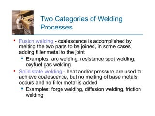
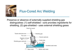
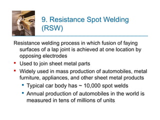
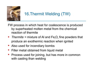
WELDING PROCESSES
ME8352: MANUFACTURING TECHNOLOGY - I
Prepared by
Prof.S.Kannan
Assistant Professor
Department of Mechanical Engineering
Vel Tech Engineering College
Avadi-Chennai-62
Two Categories of Welding
Processes
 Fusion welding - coalescence is accomplished by
melting the two parts to be joined, in some cases
adding filler metal to the joint
 Examples: arc welding, resistance spot welding,
oxyfuel gas welding
 Solid state welding - heat and/or pressure are used to
achieve coalescence, but no melting of base metals
occurs and no filler metal is added
 Examples: forge welding, diffusion welding, friction
welding
Arc Welding (AW)
A fusion welding process in which coalescence of the
metals is achieved by the heat from an electric arc
between an electrode and the work
 Electric energy from the arc produces temperatures ~
10,000 F (5500 C), hot enough to melt any metal
 Most AW processes add filler metal to increase
volume and strength of weld joint
 A pool of molten metal is formed near electrode tip,
and as electrode is moved along joint, molten weld
pool solidifies in its wake
Arc Welding
1. Shielded Metal Arc Welding
Uses a consumable electrode consisting of a filler metal
rod coated with chemicals that provide flux and
shielding
 Sometimes called "stick welding"
 Power supply, connecting cables, and electrode
holder available for a few thousand dollars
TYPES OF WELDING
Shielded Metal Arc Welding
SMAW Applications
 Used for steels, stainless steels, cast irons,
and certain nonferrous alloys
 Not used or rarely used for aluminum and its
alloys, copper alloys, and titanium
2. Gas Metal Arc Welding (MIG)
Uses a consumable bare metal wire as electrode with
shielding by flooding arc with a gas
 Wire is fed continuously and automatically from a
spool through the welding gun
 Shielding gases include argon and helium for
aluminum welding, and CO2 for steel welding
 Bare electrode wire plus shielding gases eliminate
slag on weld bead
 No need for manual grinding and cleaning of slag
Gas Metal Arc Welding
GMAW Advantages over SMAW
 Better arc time because of continuous wire electrode
 Sticks must be periodically changed in SMAW
 Better use of electrode filler metal than SMAW
 End of stick cannot be used in SMAW
 Higher deposition rates
 Eliminates problem of slag removal
 Can be readily automated
3. Flux Cored Arc Welding‑
(FCAW)
Adaptation of shielded metal arc welding, to overcome
limitations of stick electrodes - two versions
 Self shielded FCAW - core includes compounds‑
that produce shielding gases
 Gas shielded FCAW - uses externally applied‑
shielding gases
 Electrode is a continuous consumable tubing (in
coils) containing flux and other ingredients (e.g.,
alloying elements) in its core
Presence or absence of externally supplied shielding gas
distinguishes: (1) self shielded - core provides ingredients for‑
shielding, (2) gas shielded - uses external shielding gases‑
Flux-Cored Arc Welding
4. Electro slag Welding
Uses a continuous consumable electrode, flux cored‑
wire or bare wire with externally supplied shielding
gases, and molding shoes to contain molten metal
 When flux cored electrode wire is used and no‑
external gases are supplied, then special case of
self shielded FCAW‑
 When a bare electrode wire used with shielding
gases from external source, then special case of
GMAW
 Electrogas welding using flux cored electrode wire: (a)‑
front view with molding shoe removed for clarity, and (b)
side view showing molding shoes on both sides
Electro slag Welding
5. Submerged Arc Welding
(SAW)
Uses a continuous, consumable bare wire electrode,
with arc shielding by a cover of granular flux
 Electrode wire is fed automatically from a coil
 Flux introduced into joint slightly ahead of arc by
gravity from a hopper
 Completely submerges operation, preventing
sparks, spatter, and radiation
Submerged Arc Welding
SAW Applications and Products
 Steel fabrication of structural shapes (e.g., I beams)‑
 Seams for large diameter pipes, tanks, and pressure
vessels
 Welded components for heavy machinery
 Most steels (except hi C steel)
 Not good for nonferrous metals
Nonconsumable Electrode
Processes
 Gas Tungsten Arc Welding
 Plasma Arc Welding
 Carbon Arc Welding
 Stud Welding
6. Gas Tungsten Arc Welding
(TIG)
Uses a nonconsumable tungsten electrode and an inert
gas for arc shielding
 Melting point of tungsten = 3410°C (6170°F)
 A.k.a. Tungsten Inert Gas (TIG) welding
 In Europe, called "WIG welding"
 Used with or without a filler metal
 When filler metal used, it is added to weld pool
from separate rod or wire
 Applications: aluminum and stainless steel mostly
Gas Tungsten Arc Welding
Advantages and Disadvantages
of GTAW
Advantages:
 High quality welds for suitable applications
 No spatter because no filler metal through arc
 Little or no post-weld cleaning because no flux
Disadvantages:
 Generally slower and more costly than consumable
electrode AW processes
7. Plasma Arc Welding (PAW)
Special form of GTAW in which a constricted plasma arc
is directed at weld area
 Tungsten electrode is contained in a nozzle that
focuses a high velocity stream of inert gas (argon)
into arc region to form a high velocity, intensely hot
plasma arc stream
 Temperatures in PAW reach 28,000°C (50,000°F),
due to constriction of arc, producing a plasma jet of
small diameter and very high energy density
Plasma Arc Welding
Advantages and Disadvantages
of PAW
Advantages:
 Good arc stability and excellent weld quality
 Better penetration control than other AW processes
 High travel speeds
 Can be used to weld almost any metals
Disadvantages:
 High equipment cost
 Larger torch size than other AW processes
 Tends to restrict access in some joints
8. Resistance Welding (RW)
A group of fusion welding processes that use a
combination of heat and pressure to accomplish
coalescence
 Heat generated by electrical resistance to current
flow at junction to be welded
 Principal RW process is resistance spot welding
(RSW)
Resistance Welding
 Resistance welding,
showing components
in spot welding, the
main process in the
RW group
Components in Resistance Spot
Welding
 Parts to be welded (usually sheet metal)
 Two opposing electrodes
 Means of applying pressure to squeeze parts
between electrodes
 Power supply from which a controlled current can be
applied for a specified time duration
Advantages and Drawbacks of
Resistance Welding
Advantages:
 No filler metal required
 High production rates possible
 Lends itself to mechanization and automation
 Lower operator skill level than for arc welding
 Good repeatability and reliability
Disadvantages:
 High initial equipment cost
 Limited to lap joints for most RW processes
9. Resistance Spot Welding
(RSW)
Resistance welding process in which fusion of faying
surfaces of a lap joint is achieved at one location by
opposing electrodes
 Used to join sheet metal parts
 Widely used in mass production of automobiles, metal
furniture, appliances, and other sheet metal products
 Typical car body has ~ 10,000 spot welds
 Annual production of automobiles in the world is
measured in tens of millions of units
 (a) Spot welding cycle
 (b) Plot of force and
current
 Cycle: (1) parts
inserted between
electrodes, (2)
electrodes close, (3)
current on, (4) current
off, (5) electrodes
opened
Spot Welding Cycle
10.Resistance Seam Welding
(RSEW)
Uses rotating wheel electrodes to produce a
series of overlapping spot welds along lap joint
 Can produce air tight joints‑
 Applications:
 Gasoline tanks
 Automobile mufflers
 Various sheet metal containers
Resistance Seam Welding
11. Resistance Projection
Welding (RPW)
A resistance welding process in which coalescence
occurs at one or more small contact points on the
parts
 Contact points determined by design of parts to be
joined
 May consist of projections, embossments, or
localized intersections of parts
 (1) Start of operation, contact between parts is at
projections; (2) when current is applied, weld nuggets
similar to spot welding are formed at the projections
Resistance Projection Welding
Other Resistance Projection
Welding Operations
 (a) Welding of fastener on sheetmetal and (b) cross-
wire welding
12.Oxyfuel Gas Welding (OFW)
Group of fusion welding operations that burn various
fuels mixed with oxygen
 OFW employs several types of gases, which is the
primary distinction among the members of this group
 Oxyfuel gas is also used in flame cutting torches to
cut and separate metal plates and other parts
 Most important OFW process is oxyacetylene
welding
13.Oxyacetylene Welding (OAW)
Fusion welding performed by a high temperature flame
from combustion of acetylene and oxygen
 Flame is directed by a welding torch
 Filler metal is sometimes added
 Composition must be similar to base metal
 Filler rod often coated with flux to clean surfaces
and prevent oxidation
Oxyacetylene Welding
Acetylene (C2H2)
 Most popular fuel among OFW group because it is
capable of higher temperatures than any other
 Up to 3480°C (6300°F)
 Two stage reaction of acetylene and oxygen:
 First stage reaction (inner cone of flame)
C2H2 + O2 → 2CO + H2 + heat
 Second stage reaction (outer envelope)
2CO + H2 + 1.5O2 → 2CO2 + H2O + heat
 Maximum temperature reached at tip of inner cone, while
outer envelope spreads out and shields work surface from
atmosphere
 Shown below is neutral flame of oxyacetylene torch
indicating temperatures achieved
Oxyacetylene Torch
Safety Issue in OAW
 Together, acetylene and oxygen are highly flammable
 C2H2 is colorless and odorless
 It is therefore processed to have characteristic
garlic odor
OAW Safety Issue
 C2H2 is physically unstable at pressures much above 15
lb/in2
(about 1 atm)
 Storage cylinders are packed with porous filler
material saturated with acetone (CH3COCH3)
 Acetone dissolves about 25 times its own volume
of acetylene
 Different screw threads are standard on C2H2 and O2
cylinders and hoses to avoid accidental connection of
wrong gases
Alternative Gases for OFW
 Methylacetylene Propadiene (MAPP)‑
 Hydrogen
 Propylene
 Propane
 Natural Gas
Other Fusion Welding Processes
FW processes that cannot be classified as arc,
resistance, or oxyfuel welding
 Use unique technologies to develop heat for melting
 Applications are typically unique
 Processes include:
 Electron beam welding
 Laser beam welding
 Electroslag welding
 Thermit welding
14.Electron Beam Welding
(EBW)
Fusion welding process in which heat for welding is
provided by a highly focused, high intensity stream of‑ ‑
electrons striking work surface
 Electron beam gun operates at:
 High voltage (e.g., 10 to 150 kV typical) to
accelerate electrons
 Beam currents are low (measured in milliamps)
 Power in EBW not exceptional, but power density is
EBW Vacuum Chamber
 When first developed, EBW had to be carried out in a
vacuum chamber to minimize disruption of electron
beam by air molecules
 Serious inconvenience in production
 Pumpdown time can take as long as an hour
Three Vacuum Levels in EBW
1. High-vacuum welding – welding in same vacuum
chamber as beam generation to produce highest
quality weld
2. Medium-vacuum welding – welding in separate
chamber but partial vacuum reduces pump-down time
3. Non-vacuum welding – welding done at or near
atmospheric pressure, with work positioned close to
electron beam generator - requires vacuum divider to
separate work from beam generator
EBW Advantages and
Disadvantages of EBW
Advantages:
 High quality welds, deep and narrow profiles‑
 Limited heat affected zone, low thermal distortion
 No flux or shielding gases needed
Disadvantages:
 High equipment cost
 Precise joint preparation & alignment required
 Vacuum chamber required
 Safety concern: EBW generates x rays‑
15.Laser Beam Welding (LBW)
Fusion welding process in which coalescence is
achieved by energy of a highly concentrated,
coherent light beam focused on joint
 LBW normally performed with shielding gases to
prevent oxidation
 Filler metal not usually added
 High power density in small area
 So LBW often used for small parts
Comparison: LBW vs. EBW
 No vacuum chamber required for LBW
 No x rays emitted in LBW‑
 Laser beams can be focused and directed by optical
lenses and mirrors
 LBW not capable of the deep welds and high
depth to width ratios of EBW‑ ‑
 Maximum LBW depth = ~ 19 mm (3/4 in), whereas
EBW depths = 50 mm (2 in)
16.Thermit Welding (TW)
FW process in which heat for coalescence is produced
by superheated molten metal from the chemical
reaction of thermite
 Thermite = mixture of Al and Fe3O4 fine powders that
produce an exothermic reaction when ignited
 Also used for incendiary bombs
 Filler metal obtained from liquid metal
 Process used for joining, but has more in common
with casting than welding
 (1) Thermit ignited; (2) crucible tapped, superheated metal
flows into mold; (3) metal solidifies to produce weld joint
Thermit Welding
TW Applications
 Joining of railroad rails
 Repair of cracks in large steel castings and forgings
 Weld surface is often smooth enough that no
finishing is required
17.Solid State Welding (SSW)
 Coalescence of part surfaces is achieved by:
 Pressure alone, or
 Heat and pressure
 If both heat and pressure are used, heat is not
enough to melt work surfaces
 For some SSW processes, time is also a factor
 No filler metal is added
 Each SSW process has its own way of creating a
bond at the faying surfaces
Success Factors in SSW
 Essential factors for a successful solid state weld are
that the two faying surfaces must be:
 Very clean
 In very close physical contact with each other to
permit atomic bonding
SSW Advantages over FW
Processes
 If no melting, then no heat affected zone, so metal
around joint retains original properties
 Many SSW processes produce welded joints that
bond the entire contact interface between two parts
rather than at distinct spots or seams
 Some SSW processes can be used to bond
dissimilar metals, without concerns about relative
melting points, thermal expansions, and other
problems that arise in FW
Solid State Welding Processes
 Forge welding
 Cold welding
 Roll welding
 Hot pressure welding
 Diffusion welding
 Explosion welding
 Friction welding
 Ultrasonic welding
18.Forge Welding
Welding process in which components to be joined are
heated to hot working temperature range and then
forged together by hammering or similar means
 Historic significance in development of manufacturing
technology
 Process dates from about 1000 B.C., when
blacksmiths learned to weld two pieces of metal
 Of minor commercial importance today except for its
variants
19.Cold Welding (CW)
SSW process done by applying high pressure between
clean contacting surfaces at room temperature
 Cleaning usually done by degreasing and wire
brushing immediately before joining
 No heat is applied, but deformation raises work
temperature
 At least one of the metals, preferably both, must be
very ductile
 Soft aluminum and copper suited to CW
 Applications: making electrical connections
20.Roll Welding (ROW)
SSW process in which pressure sufficient to cause
coalescence is applied by means of rolls, either with
or without external heat
 Variation of either forge welding or cold welding,
depending on whether heating of workparts is done
prior to process
 If no external heat, called cold roll welding
 If heat is supplied, hot roll welding
21.Roll Welding
Roll Welding Applications
 Cladding stainless steel to mild or low alloy steel for
corrosion resistance
 Bimetallic strips for measuring temperature
 "Sandwich" coins for U.S mint
22.Diffusion Welding (DFW)
SSW process uses heat and pressure, usually in a
controlled atmosphere, with sufficient time for
diffusion and coalescence to occur
 Temperatures ≤ 0.5 Tm
 Plastic deformation at surfaces is minimal
 Primary coalescence mechanism is solid state
diffusion
 Limitation: time required for diffusion can range from
seconds to hours
DFW Applications
 Joining of high strength and refractory metals in‑
aerospace and nuclear industries
 Can be used to join either similar and dissimilar
metals
 For joining dissimilar metals, a filler layer of
different metal is often sandwiched between base
metals to promote diffusion
23.Explosion Welding (EXW)
SSW process in which rapid coalescence of two
metallic surfaces is caused by the energy of a
detonated explosive
 No filler metal used
 No external heat applied
 No diffusion occurs - time is too short
 Bonding is metallurgical, combined with mechanical
interlocking that results from a rippled or wavy
interface between the metals
Explosive Welding
 Commonly used to bond two dissimilar metals, e.g., to
clad one metal on top of a base metal over large areas
 (1) Setup in parallel configuration, and (2) during
detonation of the explosive charge
24.Friction Welding (FRW)
SSW process in which coalescence is achieved by
frictional heat combined with pressure
 When properly carried out, no melting occurs at
faying surfaces
 No filler metal, flux, or shielding gases normally used
 Process yields a narrow HAZ
 Can be used to join dissimilar metals
 Widely used commercial process, amenable to
automation and mass production
 (1) Rotating part, no contact; (2) parts brought into contact
to generate friction heat; (3) rotation stopped and axial
pressure applied; and (4) weld created
Friction Welding
Applications and Limitations of
Friction Welding
Applications:
 Shafts and tubular parts
 Industries: automotive, aircraft, farm equipment,
petroleum and natural gas
Limitations:
 At least one of the parts must be rotational
 Flash must usually be removed (extra operation)
 Upsetting reduces the part lengths (which must be
taken into consideration in product design)
25.Friction Stir Welding (FSW)
SSW process in which a rotating tool is fed along a joint
line between two workpieces, generating friction heat
and mechanically stirring the metal to form the weld
seam
 Distinguished from FRW because heat is generated
by a separate wear-resistant tool rather than the
parts
 Applications: butt joints in large aluminum parts in
aerospace, automotive, and shipbuilding
Friction Stir Welding
 (1) Rotating tool just before entering work, and (2)
partially completed weld seam
Advantages and Disadvantages
of Friction Stir Welding
 Advantages
 Good mechanical properties of weld joint
 Avoids toxic fumes, warping, and shielding issues
 Little distortion or shrinkage
 Good weld appearance
 Disadvantages
 An exit hole is produce when tool is withdrawn
 Heavy duty clamping of parts is required
26.Ultrasonic Welding (USW)
Two components are held together, and oscillatory
shear stresses of ultrasonic frequency are applied to
interface to cause coalescence
 Oscillatory motion breaks down any surface films to
allow intimate contact and strong metallurgical
bonding between surfaces
 Temperatures are well below Tm
 No filler metals, fluxes, or shielding gases
 Generally limited to lap joints on soft materials
 (a) General setup for a lap joint; and (b) close up of‑
weld area
Ultrasonic Welding
USW Applications
 Wire terminations and splicing in electrical and
electronics industry
 Eliminates need for soldering
 Assembly of aluminum sheet metal panels
 Welding of tubes to sheets in solar panels
 Assembly of small parts in automotive industry
Welding and types

Welding and types

  • 1.
    WELDING PROCESSES ME8352: MANUFACTURINGTECHNOLOGY - I Prepared by Prof.S.Kannan Assistant Professor Department of Mechanical Engineering Vel Tech Engineering College Avadi-Chennai-62
  • 2.
    Two Categories ofWelding Processes  Fusion welding - coalescence is accomplished by melting the two parts to be joined, in some cases adding filler metal to the joint  Examples: arc welding, resistance spot welding, oxyfuel gas welding  Solid state welding - heat and/or pressure are used to achieve coalescence, but no melting of base metals occurs and no filler metal is added  Examples: forge welding, diffusion welding, friction welding
  • 3.
    Arc Welding (AW) Afusion welding process in which coalescence of the metals is achieved by the heat from an electric arc between an electrode and the work  Electric energy from the arc produces temperatures ~ 10,000 F (5500 C), hot enough to melt any metal  Most AW processes add filler metal to increase volume and strength of weld joint
  • 4.
     A poolof molten metal is formed near electrode tip, and as electrode is moved along joint, molten weld pool solidifies in its wake Arc Welding
  • 5.
    1. Shielded MetalArc Welding Uses a consumable electrode consisting of a filler metal rod coated with chemicals that provide flux and shielding  Sometimes called "stick welding"  Power supply, connecting cables, and electrode holder available for a few thousand dollars TYPES OF WELDING
  • 6.
  • 7.
    SMAW Applications  Usedfor steels, stainless steels, cast irons, and certain nonferrous alloys  Not used or rarely used for aluminum and its alloys, copper alloys, and titanium
  • 8.
    2. Gas MetalArc Welding (MIG) Uses a consumable bare metal wire as electrode with shielding by flooding arc with a gas  Wire is fed continuously and automatically from a spool through the welding gun  Shielding gases include argon and helium for aluminum welding, and CO2 for steel welding  Bare electrode wire plus shielding gases eliminate slag on weld bead  No need for manual grinding and cleaning of slag
  • 9.
  • 10.
    GMAW Advantages overSMAW  Better arc time because of continuous wire electrode  Sticks must be periodically changed in SMAW  Better use of electrode filler metal than SMAW  End of stick cannot be used in SMAW  Higher deposition rates  Eliminates problem of slag removal  Can be readily automated
  • 11.
    3. Flux CoredArc Welding‑ (FCAW) Adaptation of shielded metal arc welding, to overcome limitations of stick electrodes - two versions  Self shielded FCAW - core includes compounds‑ that produce shielding gases  Gas shielded FCAW - uses externally applied‑ shielding gases  Electrode is a continuous consumable tubing (in coils) containing flux and other ingredients (e.g., alloying elements) in its core
  • 12.
    Presence or absenceof externally supplied shielding gas distinguishes: (1) self shielded - core provides ingredients for‑ shielding, (2) gas shielded - uses external shielding gases‑ Flux-Cored Arc Welding
  • 13.
    4. Electro slagWelding Uses a continuous consumable electrode, flux cored‑ wire or bare wire with externally supplied shielding gases, and molding shoes to contain molten metal  When flux cored electrode wire is used and no‑ external gases are supplied, then special case of self shielded FCAW‑  When a bare electrode wire used with shielding gases from external source, then special case of GMAW
  • 14.
     Electrogas weldingusing flux cored electrode wire: (a)‑ front view with molding shoe removed for clarity, and (b) side view showing molding shoes on both sides Electro slag Welding
  • 15.
    5. Submerged ArcWelding (SAW) Uses a continuous, consumable bare wire electrode, with arc shielding by a cover of granular flux  Electrode wire is fed automatically from a coil  Flux introduced into joint slightly ahead of arc by gravity from a hopper  Completely submerges operation, preventing sparks, spatter, and radiation
  • 16.
  • 17.
    SAW Applications andProducts  Steel fabrication of structural shapes (e.g., I beams)‑  Seams for large diameter pipes, tanks, and pressure vessels  Welded components for heavy machinery  Most steels (except hi C steel)  Not good for nonferrous metals
  • 18.
    Nonconsumable Electrode Processes  GasTungsten Arc Welding  Plasma Arc Welding  Carbon Arc Welding  Stud Welding
  • 19.
    6. Gas TungstenArc Welding (TIG) Uses a nonconsumable tungsten electrode and an inert gas for arc shielding  Melting point of tungsten = 3410°C (6170°F)  A.k.a. Tungsten Inert Gas (TIG) welding  In Europe, called "WIG welding"  Used with or without a filler metal  When filler metal used, it is added to weld pool from separate rod or wire  Applications: aluminum and stainless steel mostly
  • 20.
  • 21.
    Advantages and Disadvantages ofGTAW Advantages:  High quality welds for suitable applications  No spatter because no filler metal through arc  Little or no post-weld cleaning because no flux Disadvantages:  Generally slower and more costly than consumable electrode AW processes
  • 22.
    7. Plasma ArcWelding (PAW) Special form of GTAW in which a constricted plasma arc is directed at weld area  Tungsten electrode is contained in a nozzle that focuses a high velocity stream of inert gas (argon) into arc region to form a high velocity, intensely hot plasma arc stream  Temperatures in PAW reach 28,000°C (50,000°F), due to constriction of arc, producing a plasma jet of small diameter and very high energy density
  • 23.
  • 24.
    Advantages and Disadvantages ofPAW Advantages:  Good arc stability and excellent weld quality  Better penetration control than other AW processes  High travel speeds  Can be used to weld almost any metals Disadvantages:  High equipment cost  Larger torch size than other AW processes  Tends to restrict access in some joints
  • 25.
    8. Resistance Welding(RW) A group of fusion welding processes that use a combination of heat and pressure to accomplish coalescence  Heat generated by electrical resistance to current flow at junction to be welded  Principal RW process is resistance spot welding (RSW)
  • 26.
    Resistance Welding  Resistancewelding, showing components in spot welding, the main process in the RW group
  • 27.
    Components in ResistanceSpot Welding  Parts to be welded (usually sheet metal)  Two opposing electrodes  Means of applying pressure to squeeze parts between electrodes  Power supply from which a controlled current can be applied for a specified time duration
  • 28.
    Advantages and Drawbacksof Resistance Welding Advantages:  No filler metal required  High production rates possible  Lends itself to mechanization and automation  Lower operator skill level than for arc welding  Good repeatability and reliability Disadvantages:  High initial equipment cost  Limited to lap joints for most RW processes
  • 29.
    9. Resistance SpotWelding (RSW) Resistance welding process in which fusion of faying surfaces of a lap joint is achieved at one location by opposing electrodes  Used to join sheet metal parts  Widely used in mass production of automobiles, metal furniture, appliances, and other sheet metal products  Typical car body has ~ 10,000 spot welds  Annual production of automobiles in the world is measured in tens of millions of units
  • 30.
     (a) Spotwelding cycle  (b) Plot of force and current  Cycle: (1) parts inserted between electrodes, (2) electrodes close, (3) current on, (4) current off, (5) electrodes opened Spot Welding Cycle
  • 31.
    10.Resistance Seam Welding (RSEW) Usesrotating wheel electrodes to produce a series of overlapping spot welds along lap joint  Can produce air tight joints‑  Applications:  Gasoline tanks  Automobile mufflers  Various sheet metal containers
  • 32.
  • 33.
    11. Resistance Projection Welding(RPW) A resistance welding process in which coalescence occurs at one or more small contact points on the parts  Contact points determined by design of parts to be joined  May consist of projections, embossments, or localized intersections of parts
  • 34.
     (1) Startof operation, contact between parts is at projections; (2) when current is applied, weld nuggets similar to spot welding are formed at the projections Resistance Projection Welding
  • 35.
    Other Resistance Projection WeldingOperations  (a) Welding of fastener on sheetmetal and (b) cross- wire welding
  • 36.
    12.Oxyfuel Gas Welding(OFW) Group of fusion welding operations that burn various fuels mixed with oxygen  OFW employs several types of gases, which is the primary distinction among the members of this group  Oxyfuel gas is also used in flame cutting torches to cut and separate metal plates and other parts  Most important OFW process is oxyacetylene welding
  • 37.
    13.Oxyacetylene Welding (OAW) Fusionwelding performed by a high temperature flame from combustion of acetylene and oxygen  Flame is directed by a welding torch  Filler metal is sometimes added  Composition must be similar to base metal  Filler rod often coated with flux to clean surfaces and prevent oxidation
  • 38.
  • 39.
    Acetylene (C2H2)  Mostpopular fuel among OFW group because it is capable of higher temperatures than any other  Up to 3480°C (6300°F)  Two stage reaction of acetylene and oxygen:  First stage reaction (inner cone of flame) C2H2 + O2 → 2CO + H2 + heat  Second stage reaction (outer envelope) 2CO + H2 + 1.5O2 → 2CO2 + H2O + heat
  • 40.
     Maximum temperaturereached at tip of inner cone, while outer envelope spreads out and shields work surface from atmosphere  Shown below is neutral flame of oxyacetylene torch indicating temperatures achieved Oxyacetylene Torch
  • 41.
    Safety Issue inOAW  Together, acetylene and oxygen are highly flammable  C2H2 is colorless and odorless  It is therefore processed to have characteristic garlic odor
  • 42.
    OAW Safety Issue C2H2 is physically unstable at pressures much above 15 lb/in2 (about 1 atm)  Storage cylinders are packed with porous filler material saturated with acetone (CH3COCH3)  Acetone dissolves about 25 times its own volume of acetylene  Different screw threads are standard on C2H2 and O2 cylinders and hoses to avoid accidental connection of wrong gases
  • 43.
    Alternative Gases forOFW  Methylacetylene Propadiene (MAPP)‑  Hydrogen  Propylene  Propane  Natural Gas
  • 44.
    Other Fusion WeldingProcesses FW processes that cannot be classified as arc, resistance, or oxyfuel welding  Use unique technologies to develop heat for melting  Applications are typically unique  Processes include:  Electron beam welding  Laser beam welding  Electroslag welding  Thermit welding
  • 45.
    14.Electron Beam Welding (EBW) Fusionwelding process in which heat for welding is provided by a highly focused, high intensity stream of‑ ‑ electrons striking work surface  Electron beam gun operates at:  High voltage (e.g., 10 to 150 kV typical) to accelerate electrons  Beam currents are low (measured in milliamps)  Power in EBW not exceptional, but power density is
  • 46.
    EBW Vacuum Chamber When first developed, EBW had to be carried out in a vacuum chamber to minimize disruption of electron beam by air molecules  Serious inconvenience in production  Pumpdown time can take as long as an hour
  • 47.
    Three Vacuum Levelsin EBW 1. High-vacuum welding – welding in same vacuum chamber as beam generation to produce highest quality weld 2. Medium-vacuum welding – welding in separate chamber but partial vacuum reduces pump-down time 3. Non-vacuum welding – welding done at or near atmospheric pressure, with work positioned close to electron beam generator - requires vacuum divider to separate work from beam generator
  • 48.
    EBW Advantages and Disadvantagesof EBW Advantages:  High quality welds, deep and narrow profiles‑  Limited heat affected zone, low thermal distortion  No flux or shielding gases needed Disadvantages:  High equipment cost  Precise joint preparation & alignment required  Vacuum chamber required  Safety concern: EBW generates x rays‑
  • 49.
    15.Laser Beam Welding(LBW) Fusion welding process in which coalescence is achieved by energy of a highly concentrated, coherent light beam focused on joint  LBW normally performed with shielding gases to prevent oxidation  Filler metal not usually added  High power density in small area  So LBW often used for small parts
  • 50.
    Comparison: LBW vs.EBW  No vacuum chamber required for LBW  No x rays emitted in LBW‑  Laser beams can be focused and directed by optical lenses and mirrors  LBW not capable of the deep welds and high depth to width ratios of EBW‑ ‑  Maximum LBW depth = ~ 19 mm (3/4 in), whereas EBW depths = 50 mm (2 in)
  • 51.
    16.Thermit Welding (TW) FWprocess in which heat for coalescence is produced by superheated molten metal from the chemical reaction of thermite  Thermite = mixture of Al and Fe3O4 fine powders that produce an exothermic reaction when ignited  Also used for incendiary bombs  Filler metal obtained from liquid metal  Process used for joining, but has more in common with casting than welding
  • 52.
     (1) Thermitignited; (2) crucible tapped, superheated metal flows into mold; (3) metal solidifies to produce weld joint Thermit Welding
  • 53.
    TW Applications  Joiningof railroad rails  Repair of cracks in large steel castings and forgings  Weld surface is often smooth enough that no finishing is required
  • 54.
    17.Solid State Welding(SSW)  Coalescence of part surfaces is achieved by:  Pressure alone, or  Heat and pressure  If both heat and pressure are used, heat is not enough to melt work surfaces  For some SSW processes, time is also a factor  No filler metal is added  Each SSW process has its own way of creating a bond at the faying surfaces
  • 55.
    Success Factors inSSW  Essential factors for a successful solid state weld are that the two faying surfaces must be:  Very clean  In very close physical contact with each other to permit atomic bonding
  • 56.
    SSW Advantages overFW Processes  If no melting, then no heat affected zone, so metal around joint retains original properties  Many SSW processes produce welded joints that bond the entire contact interface between two parts rather than at distinct spots or seams  Some SSW processes can be used to bond dissimilar metals, without concerns about relative melting points, thermal expansions, and other problems that arise in FW
  • 57.
    Solid State WeldingProcesses  Forge welding  Cold welding  Roll welding  Hot pressure welding  Diffusion welding  Explosion welding  Friction welding  Ultrasonic welding
  • 58.
    18.Forge Welding Welding processin which components to be joined are heated to hot working temperature range and then forged together by hammering or similar means  Historic significance in development of manufacturing technology  Process dates from about 1000 B.C., when blacksmiths learned to weld two pieces of metal  Of minor commercial importance today except for its variants
  • 59.
    19.Cold Welding (CW) SSWprocess done by applying high pressure between clean contacting surfaces at room temperature  Cleaning usually done by degreasing and wire brushing immediately before joining  No heat is applied, but deformation raises work temperature  At least one of the metals, preferably both, must be very ductile  Soft aluminum and copper suited to CW  Applications: making electrical connections
  • 60.
    20.Roll Welding (ROW) SSWprocess in which pressure sufficient to cause coalescence is applied by means of rolls, either with or without external heat  Variation of either forge welding or cold welding, depending on whether heating of workparts is done prior to process  If no external heat, called cold roll welding  If heat is supplied, hot roll welding
  • 61.
  • 62.
    Roll Welding Applications Cladding stainless steel to mild or low alloy steel for corrosion resistance  Bimetallic strips for measuring temperature  "Sandwich" coins for U.S mint
  • 63.
    22.Diffusion Welding (DFW) SSWprocess uses heat and pressure, usually in a controlled atmosphere, with sufficient time for diffusion and coalescence to occur  Temperatures ≤ 0.5 Tm  Plastic deformation at surfaces is minimal  Primary coalescence mechanism is solid state diffusion  Limitation: time required for diffusion can range from seconds to hours
  • 64.
    DFW Applications  Joiningof high strength and refractory metals in‑ aerospace and nuclear industries  Can be used to join either similar and dissimilar metals  For joining dissimilar metals, a filler layer of different metal is often sandwiched between base metals to promote diffusion
  • 65.
    23.Explosion Welding (EXW) SSWprocess in which rapid coalescence of two metallic surfaces is caused by the energy of a detonated explosive  No filler metal used  No external heat applied  No diffusion occurs - time is too short  Bonding is metallurgical, combined with mechanical interlocking that results from a rippled or wavy interface between the metals
  • 66.
    Explosive Welding  Commonlyused to bond two dissimilar metals, e.g., to clad one metal on top of a base metal over large areas  (1) Setup in parallel configuration, and (2) during detonation of the explosive charge
  • 67.
    24.Friction Welding (FRW) SSWprocess in which coalescence is achieved by frictional heat combined with pressure  When properly carried out, no melting occurs at faying surfaces  No filler metal, flux, or shielding gases normally used  Process yields a narrow HAZ  Can be used to join dissimilar metals  Widely used commercial process, amenable to automation and mass production
  • 68.
     (1) Rotatingpart, no contact; (2) parts brought into contact to generate friction heat; (3) rotation stopped and axial pressure applied; and (4) weld created Friction Welding
  • 69.
    Applications and Limitationsof Friction Welding Applications:  Shafts and tubular parts  Industries: automotive, aircraft, farm equipment, petroleum and natural gas Limitations:  At least one of the parts must be rotational  Flash must usually be removed (extra operation)  Upsetting reduces the part lengths (which must be taken into consideration in product design)
  • 70.
    25.Friction Stir Welding(FSW) SSW process in which a rotating tool is fed along a joint line between two workpieces, generating friction heat and mechanically stirring the metal to form the weld seam  Distinguished from FRW because heat is generated by a separate wear-resistant tool rather than the parts  Applications: butt joints in large aluminum parts in aerospace, automotive, and shipbuilding
  • 71.
    Friction Stir Welding (1) Rotating tool just before entering work, and (2) partially completed weld seam
  • 72.
    Advantages and Disadvantages ofFriction Stir Welding  Advantages  Good mechanical properties of weld joint  Avoids toxic fumes, warping, and shielding issues  Little distortion or shrinkage  Good weld appearance  Disadvantages  An exit hole is produce when tool is withdrawn  Heavy duty clamping of parts is required
  • 73.
    26.Ultrasonic Welding (USW) Twocomponents are held together, and oscillatory shear stresses of ultrasonic frequency are applied to interface to cause coalescence  Oscillatory motion breaks down any surface films to allow intimate contact and strong metallurgical bonding between surfaces  Temperatures are well below Tm  No filler metals, fluxes, or shielding gases  Generally limited to lap joints on soft materials
  • 74.
     (a) Generalsetup for a lap joint; and (b) close up of‑ weld area Ultrasonic Welding
  • 75.
    USW Applications  Wireterminations and splicing in electrical and electronics industry  Eliminates need for soldering  Assembly of aluminum sheet metal panels  Welding of tubes to sheets in solar panels  Assembly of small parts in automotive industry