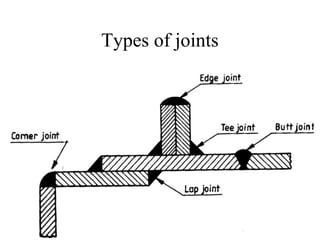
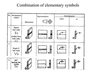
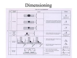
Welding is a method of permanently joining metal parts. There are different types of welded joints and standardized welding symbols are used on drawings to indicate how parts should be welded together. The symbols provide information on the type of weld, location of the weld, size of the weld, whether welding is required on one or both sides of the joint, and other details. Proper interpretation and application of welding symbols is important for ensuring parts are welded correctly.
Welding equipment's is the tools used in the welding
The following equipment's used in the welding
1. Power Source (AC or DC)
2. Electrode Holder
3. Welding Cables
4. Ground Clamp
5. Welding Electrodes
6. Welding Helmets & Hand Shield
7. Protective Cloths
8. Finishing tools – Wire brush, Chipping Hammers.
SMAW is one of the basic and most common of all welding processes. this presentation is geared towards helping the general public in understanding the fundamentals of SMAW process. Look out for my next series of publications...
Welding process
Arc Welding
Resistance Welding
Oxy fuel Gas Welding
Other Fusion Welding Processes
Solid State Welding
Weld Quality
Weld ability
Design Considerations in Welding
This presentation will help to gain all essential and industrial knowledge related to sheet metal operations, design of sheet metal product, common sheet metal materials.
education is a key for everything so the objective of this slide is to share knowledge to the glob in my area of specialization.
This lecture note is basically designed for mechanical Engineering Manufacturing stream students and Instructors.
Design & Construction Errors- How it Affects Repair and Rehabilitation of Str...Srishti Wakhloo
The ultimate guide to design and construction errors and how it affects the repair and rehabilitation of structures. This data has been compiled after visiting several websites and reading books. It is mainly for the purpose of civil engineering students for the subject "Building Maintenance and Repairs".
Earthquake Resistant Building ConstructionRohan Narvekar
This File comprises of a general information and guidelines for construction of Earthquake Resistant buildings, Its a basic study of the same and may help students and learners for overall information of this technology.
Type of Welding joints for different structureskeshavmech2008
Butt welds are welds where two pieces of metal to be joined are in the same plane.[1] These welds require only some preparation and are used with thin sheet metals that can be welded with a single pass.[2] Common issues that can weaken a butt weld are the entrapment of slag, excessive porosity, or cracking. For strong welds, the goal is to use the least amount of welding material possible. Butt welds are prevalent in automated welding processes, such as submerged-arc welding, due to their relative ease of preparation.[3] When metals are welded without human guidance, there is no operator to adjust non-ideal joint preparation. Because of this necessity, butt welds can be utilized for their simplistic design to be fed through automated welding machines efficiently.
Types
Butt joint geometries
There are many types of butt welds, but all fall within one of these categories: single-welded butt joints, double-welded butt joint, and open or closed butt joints. A single welded butt joint is the name for a joint that has only been welded from one side. A double-welded butt joint is created when the weld has been welded from both sides. With double welding, the depths of each weld can vary slightly. A closed weld is a type of joint in which the two pieces that will be joined are touching during the welding process. An open weld is the joint type where the two pieces have a small gap in between them during the welding process.
Square butt joints
The square groove is a butt welding joint with the two pieces being flat and parallel to each other. This joint is simple to prepare, economical to use, and provides satisfactory strength but is limited by joint thickness. The closed square butt weld is a type of square-groove joint with no spacing in between the pieces. This joint type is common with gas and arc welding. For thicker joints, the edge of each member of the joint must be prepared to a particular geometry to provide accessibility for welding and to ensure the desired weld soundness and strength. The opening or gap at the root of the joint and the included angle of the groove should be selected to require the least weld metal necessary to give needed access and meet strength requirements. Only metal up to 4.5mm thick is usually used for square butt joints.
V-joints
Single V welds are similar to a bevel joint, but instead of only one side having the bevelled edge, both sides of the weld joint are beveled. In thick metals, and when welding can be performed from both sides of the work piece, a double-V joint is used. When welding thicker metals, a double-V joint requires less filler material because there are two narrower V-joints compared to a wider single-V joint. Also the double-V joint helps compensate for warping forces. With a single-V joint, stress tends to warp the piece in one direction when the V-joint is filled, but with a double-V-joint, there are welds on both sides of the material, having opposing stresses, straightening the material.
J-
Mechanical Drafting welding joint, piping and duct layoutGaurav Mistry
Theory of welding joint, types, advantages, disadvantages, symbols, arrow symbol, interpretation of symbol of welding in drawing, piping layout, types, duct layout
Unleash Your Inner Demon with the "Let's Summon Demons" T-Shirt. Calling all fans of dark humor and edgy fashion! The "Let's Summon Demons" t-shirt is a unique way to express yourself and turn heads.
https://dribbble.com/shots/24253051-Let-s-Summon-Demons-Shirt
You could be a professional graphic designer and still make mistakes. There is always the possibility of human error. On the other hand if you’re not a designer, the chances of making some common graphic design mistakes are even higher. Because you don’t know what you don’t know. That’s where this blog comes in. To make your job easier and help you create better designs, we have put together a list of common graphic design mistakes that you need to avoid.
White wonder, Work developed by Eva TschoppMansi Shah
White Wonder by Eva Tschopp
A tale about our culture around the use of fertilizers and pesticides visiting small farms around Ahmedabad in Matar and Shilaj.
Expert Accessory Dwelling Unit (ADU) Drafting ServicesResDraft
Whether you’re looking to create a guest house, a rental unit, or a private retreat, our experienced team will design a space that complements your existing home and maximizes your investment. We provide personalized, comprehensive expert accessory dwelling unit (ADU)drafting solutions tailored to your needs, ensuring a seamless process from concept to completion.
13. RULES TO BE OBSERVED WHILE APPLYING SYMBOLS
1. Symbols for fillet and similar welds be shown such that the
vertical position of the symbol are indicated on the left hand
side of the symbol,irrespective of the orientation of the weld
metal.
2. If the welds are to be made on the arrow side of the joint,the
corresponding symbol should be placed either above or below
the continuous reference line (Fig.)
3. If the welds are to be made on the other side of a joint ,the
corresponding symbol should be placed above or below the
dashed reference line (Fig.)
4. If the welds are to be made on both sides of the a joint, the
corresponding symbols should be placed on both sides of the
reference line and the dashed line is not shown (Fig.)
5. The arrow of the symbol must point towards the joint which
required welding (Fig.)
14. RULES TO BE OBSERVED WHILE APPLYING SYMBOLS
6. When only one member is to be edge prepared to make the joint ,
the arrow should point at the plate (Fig. ---)
7. Dimensions of size are indicated in mm without writing the unit
mm.
8. If unequal legs of fillet are to be used ,they should also be given on
the left hand side.
9. If a welding is required to be made on the site or during erection
or assembly, it is re
10. If a weld is to be made all around a joint , a circle should also be
placed at the elbow ,connecting the arrow and the reference line.
(Fig.----)
11. If a weld is to have a flush or flat finish , a straight line should be
added above the symbol.
12. The welding process is indicated , if required ,at the end of the
arrow.(fig----)