Downloaded 106 times


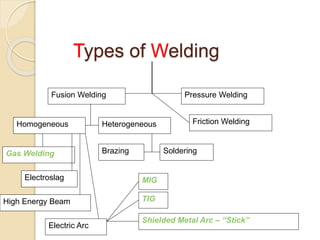
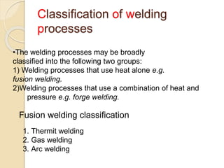
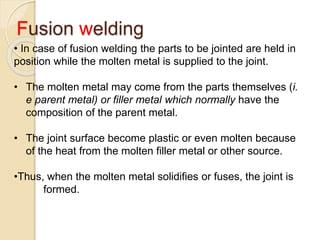
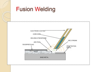


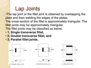


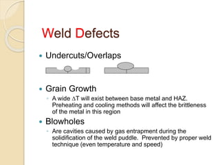


This document discusses various welding processes and welded joints. It begins by defining a welded joint as a permanent fusion of two parts together, with or without filler material. It then describes several types of welding processes including fusion welding (brazing, soldering, gas welding, electric arc welding) and pressure welding (friction, forge). The document further discusses specific fusion welding techniques like thermit welding, gas welding and electric arc welding. It also outlines common welded joint designs such as butt, lap, fillet, corner and describes joint preparation and defects that can occur.


