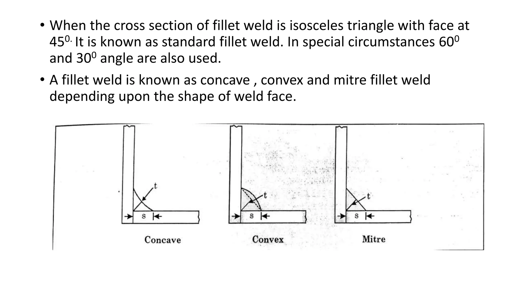
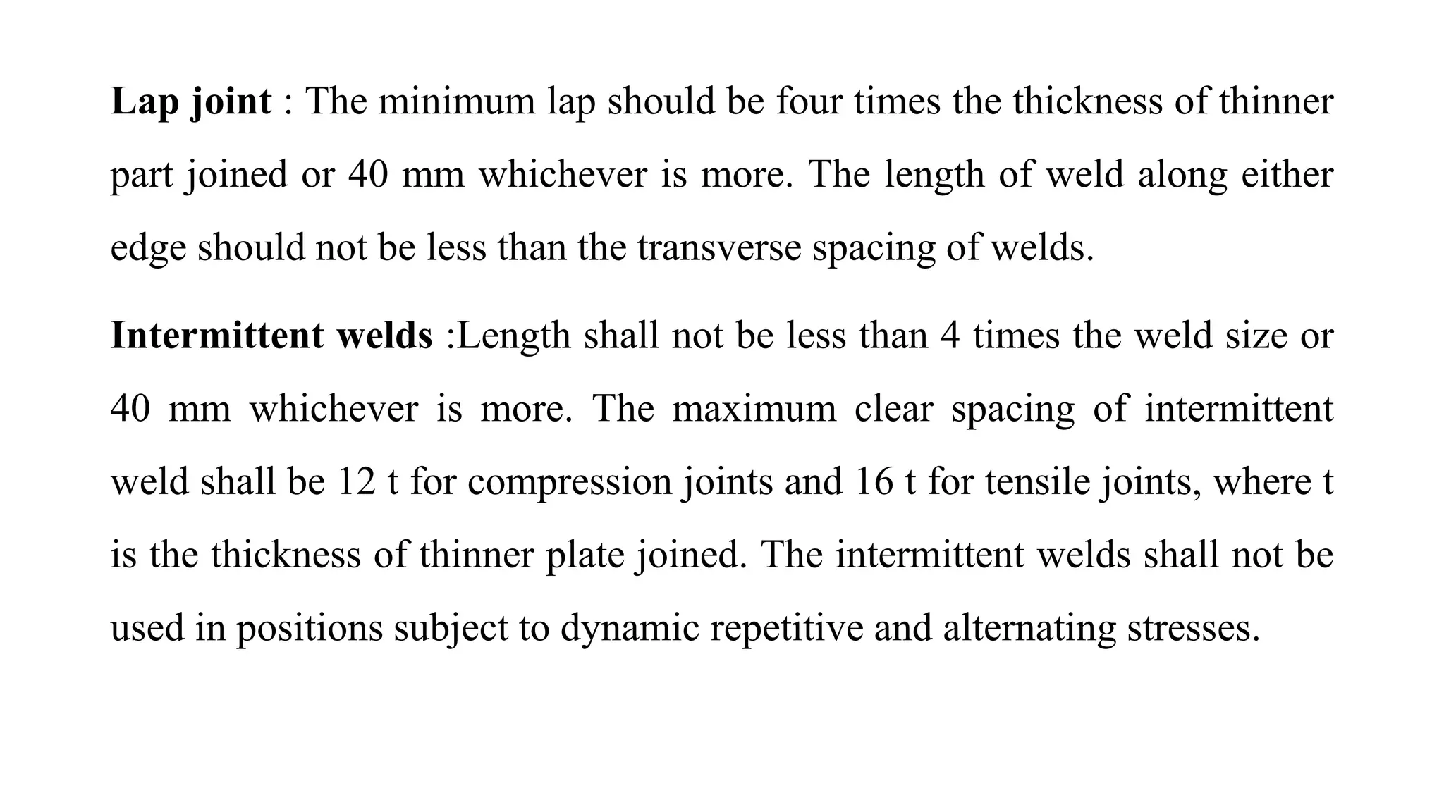
Welded Connections
by: Dinesh Nath
Welding:
• Welding consists of joining two pieces of metal by establishing a
metallurgical bod between them.
• The elements to be connected are brought closer and the metal is
melted by means of electric arc and oxyacetylene flame along with
weld rod which adds metal to the joint.
• After cooling a bond is established between the two elements.
Types of Welded joints:
1. Butt joint 2. Fillet Weld 3. Slot weld and Plug weld
Butt Joint
Butt weld is also known as groove weld. Depending upon the shape of
groove made for welding butt welds.
Fillet welds
• Fillet weld is a weld of approximately triangle X-section joining two
surfaces at right angles to each other in a lap joint, tee joint or corner
joint.
• When the cross section of fillet weld is isosceles triangle with face at
450. It is known as standard fillet weld. In special circumstances 600
and 300 angle are also used.
• A fillet weld is known as concave , convex and mitre fillet weld
depending upon the shape of weld face.
Slot weld and Plug weld
• Figure shows a typical slot weld in which a plate with circular hole is
kept with another plate to be joined and then fillet welding is made
along the periphery of the hole.
• Figure below shows typical plug welds in which small holes are made
In one plate and is kept over another plate to be connected and then
the entire hole is filled with fillet material.
Specifications for Welding:
• Butt Weld
1. The size of butt weld shall be specified by the effective throat
thickness. In case of a complete penetration butt weld it shall be
taken as thickness of the thinner part joined. Double U, double V,
double J and double level butt welds may be generally regarded as
complete penetration butt welds
2. The effective throat thickness in case of incomplete penetration butt
weld shall be taken as the minimum thickness of the weld metal
common to the parts joined excluding reinforcement. In the absence
of actual data it may be taken as 5/8th of thickness of thinner
material.
• The effective length of butt weld shall be taken as the length of full
size weld.
• The minimum length of butt weld shall be four times the size of the
weld.
• If intermittent butt welding is used, it shall have an effective length of
not less than four times the weld size and space between the two welds
shall not be more than 16 times the thickness of the thinner part joined.
Fillet Weld
1. Size of Fillet Weld
• The size of normal fillet weld shall be taken as the minimum weld leg
size.
• For deep penetration welds with penetration not less than 2.4 mm, size
of weld is minimum leg size + 2.4 mm.
• For fillet welds made by semi automatic or automatic processes with
deep penetration more than 2.4 mm, if purchaser and contractor agree
S = minimum leg size + Actual penetration.
2. Minimum size of fillet weld specified in 3 mm.
To avoid the risk of cracking in the absence of preheating the minimum size
specified are:
For less than 10 mm thickness plate — 3 mm
For 10 to 20 mm thickness plate — 5 mm
For 20 to 32 mm thickness plate — 6 mm
For 32 to 50 mm thickness plate — 8 mm
Maximum size is thickness of thinner plate minus 1.5mm
¾ of nominal thickness of angle.
3. Effective throat thickness :
It shall not be less than 3 mm and shall not generally exceed 0.7 t (or t under
special circumstances) where t is the thickness of the thinner plate at the
elements being welded.
• If the face of plates being welded are inclined to each other, the
effective throat thickness shall be taken as K times the fillet size where
K is as given in table below
4.Effective length : The effective length of the weld is the length of the
weld for which specified size and throat thickness exist. In drawings
only effective length is shown. While welding length made is equal to
effective length plus twice the size of the weld. Effective length should
not be less than 4 times the size of the weld.
Angle between fusion
faces
600-900 910-1000 1010-1060 1070-1130 1140-1200
Constant K 0.70 0.65 0.6 0.55 0.5
Lap joint : The minimum lap should be four times the thickness of thinner
part joined or 40 mm whichever is more. The length of weld along either
edge should not be less than the transverse spacing of welds.
Intermittent welds :Length shall not be less than 4 times the weld size or
40 mm whichever is more. The maximum clear spacing of intermittent
weld shall be 12 t for compression joints and 16 t for tensile joints, where t
is the thickness of thinner plate joined. The intermittent welds shall not be
used in positions subject to dynamic repetitive and alternating stresses.
Advantages of welding
1. As no hole required for welding hence no reduction of area. So
structural members are more effective in taking the load.
2. In welding filler plates, gusseted plates, connecting angles etc are
not used which leads to the reduced overall weight of the structure.
3. Welded joints are more economical as less labour & less material is
used.
4. The efficiency of welded joints is more than that of the riveted
joints
5. The welded joints looks better than the bulky riveted/bolted joints.
6. The speed of fabrication is faster in comparison with the riveted
joints
• Complete rigid joints can be provided with the welding process
• The alteration and addition of additional structures is easy.
• No noise is produced during the welding process as in case of riveting
• Any shape of joint can be made with ease.
Disadvantages:
• Welded joints are more brittle and therefore their fatigue strength is
less than the members joined.
• Due to uneven heating and cooling of members during the welding
the members distort resulting in additional stresses
• Skilled labour and electricity may required for welding
• No provision for expansion and contraction is kept hence there is
possibility of cracks.
• The inspection is difficult and costlier than the rivet connections.
• Defects like internal air pocket slag inclusion & incomplete
penetration are difficult to detect.
Design of fillet weld
Size of fillet weld (S)
Minimum – 3 mm ( <10mm )
- 5 mm ( 10 – 20 mm )
Maximum – Thinner plate – 1.5 mm or ¾ thickness of angle section
Throat of fillet weld (t)
t = KS ( K= 0.7 , 0.65 , 0.6 )
Effective length of the fillet weld (l)
l = L – 2S
Strength of fillet weld P = pq x l x t
Permissible stress in weld pq = 108 MPa
Examples:
• Design a suitable fillet weld to connect the two plates as shown
below:
10 mm
115 KN
250 mm 150mm 115 KN
8mm
• Design the welded joint as shown below assuming permissible
stresses in angles and fillet welds are 150 Mpa and 108 Mpa
respectively.
• From Sp 6 code Net area of angle = 1903 mm2
• CG From top = 71.6 mm
Design of Butt weld
Size of weld
Thickness of thinner plate – If penetrated full
5/8 times the thickness of thinner plate – If penetrated patially
The difference in thickness of two plates should not be more than 25 %
of thickness or 3 mm which ever is more. If difference more than 25 %
then tapering of 1 in 5 is to be done.
Effective length:
Minimum > 4S
L = l + 2S or l = L – 2S
• Reinforcement: The extra deposit of metals above the thinner plate
between 1 mm to 3 mm is not considered for stress calculation and
design.
• Stresses in butt weld: The stresses in butt weld should be taken equal
to the stresses of the parent metal in case of shop weld. These values
are reduced to 80% if field welding is done.
Examples:
• The plates of dimension 180 x 10 and 180 x 12 mm are joined by butt
welding. Calculate the maximum tension the joint can transmit if
a) Single V Butt weld
b) Double V Butt weld
The permissible tensile stress of plate is 150 Mpa .
• Design a butt weld to join two strip of 180 x 12 and 180 x 8 to carry
an axial tension of 110 kN
• A circular penstock of 1.2 m diameter is fabricated from 16 mm plate,
lapping it and securing with fillet weld of 10 mm size provided on the
inside and outside of the lapped ends as shown in fig. Calculate the
safe internal pressure, assuming permissible stresses in weld as
108Mpa.

Welded

  • 1.
  • 2.
    Welding: • Welding consistsof joining two pieces of metal by establishing a metallurgical bod between them. • The elements to be connected are brought closer and the metal is melted by means of electric arc and oxyacetylene flame along with weld rod which adds metal to the joint. • After cooling a bond is established between the two elements.
  • 3.
    Types of Weldedjoints: 1. Butt joint 2. Fillet Weld 3. Slot weld and Plug weld Butt Joint Butt weld is also known as groove weld. Depending upon the shape of groove made for welding butt welds.
  • 5.
    Fillet welds • Filletweld is a weld of approximately triangle X-section joining two surfaces at right angles to each other in a lap joint, tee joint or corner joint.
  • 6.
    • When thecross section of fillet weld is isosceles triangle with face at 450. It is known as standard fillet weld. In special circumstances 600 and 300 angle are also used. • A fillet weld is known as concave , convex and mitre fillet weld depending upon the shape of weld face.
  • 7.
    Slot weld andPlug weld • Figure shows a typical slot weld in which a plate with circular hole is kept with another plate to be joined and then fillet welding is made along the periphery of the hole.
  • 8.
    • Figure belowshows typical plug welds in which small holes are made In one plate and is kept over another plate to be connected and then the entire hole is filled with fillet material.
  • 9.
    Specifications for Welding: •Butt Weld 1. The size of butt weld shall be specified by the effective throat thickness. In case of a complete penetration butt weld it shall be taken as thickness of the thinner part joined. Double U, double V, double J and double level butt welds may be generally regarded as complete penetration butt welds 2. The effective throat thickness in case of incomplete penetration butt weld shall be taken as the minimum thickness of the weld metal common to the parts joined excluding reinforcement. In the absence of actual data it may be taken as 5/8th of thickness of thinner material.
  • 10.
    • The effectivelength of butt weld shall be taken as the length of full size weld. • The minimum length of butt weld shall be four times the size of the weld. • If intermittent butt welding is used, it shall have an effective length of not less than four times the weld size and space between the two welds shall not be more than 16 times the thickness of the thinner part joined.
  • 11.
    Fillet Weld 1. Sizeof Fillet Weld • The size of normal fillet weld shall be taken as the minimum weld leg size. • For deep penetration welds with penetration not less than 2.4 mm, size of weld is minimum leg size + 2.4 mm. • For fillet welds made by semi automatic or automatic processes with deep penetration more than 2.4 mm, if purchaser and contractor agree S = minimum leg size + Actual penetration.
  • 12.
    2. Minimum sizeof fillet weld specified in 3 mm. To avoid the risk of cracking in the absence of preheating the minimum size specified are: For less than 10 mm thickness plate — 3 mm For 10 to 20 mm thickness plate — 5 mm For 20 to 32 mm thickness plate — 6 mm For 32 to 50 mm thickness plate — 8 mm Maximum size is thickness of thinner plate minus 1.5mm ¾ of nominal thickness of angle. 3. Effective throat thickness : It shall not be less than 3 mm and shall not generally exceed 0.7 t (or t under special circumstances) where t is the thickness of the thinner plate at the elements being welded.
  • 13.
    • If theface of plates being welded are inclined to each other, the effective throat thickness shall be taken as K times the fillet size where K is as given in table below 4.Effective length : The effective length of the weld is the length of the weld for which specified size and throat thickness exist. In drawings only effective length is shown. While welding length made is equal to effective length plus twice the size of the weld. Effective length should not be less than 4 times the size of the weld. Angle between fusion faces 600-900 910-1000 1010-1060 1070-1130 1140-1200 Constant K 0.70 0.65 0.6 0.55 0.5
  • 14.
    Lap joint :The minimum lap should be four times the thickness of thinner part joined or 40 mm whichever is more. The length of weld along either edge should not be less than the transverse spacing of welds. Intermittent welds :Length shall not be less than 4 times the weld size or 40 mm whichever is more. The maximum clear spacing of intermittent weld shall be 12 t for compression joints and 16 t for tensile joints, where t is the thickness of thinner plate joined. The intermittent welds shall not be used in positions subject to dynamic repetitive and alternating stresses.
  • 15.
    Advantages of welding 1.As no hole required for welding hence no reduction of area. So structural members are more effective in taking the load. 2. In welding filler plates, gusseted plates, connecting angles etc are not used which leads to the reduced overall weight of the structure. 3. Welded joints are more economical as less labour & less material is used. 4. The efficiency of welded joints is more than that of the riveted joints 5. The welded joints looks better than the bulky riveted/bolted joints. 6. The speed of fabrication is faster in comparison with the riveted joints
  • 16.
    • Complete rigidjoints can be provided with the welding process • The alteration and addition of additional structures is easy. • No noise is produced during the welding process as in case of riveting • Any shape of joint can be made with ease.
  • 17.
    Disadvantages: • Welded jointsare more brittle and therefore their fatigue strength is less than the members joined. • Due to uneven heating and cooling of members during the welding the members distort resulting in additional stresses • Skilled labour and electricity may required for welding • No provision for expansion and contraction is kept hence there is possibility of cracks. • The inspection is difficult and costlier than the rivet connections. • Defects like internal air pocket slag inclusion & incomplete penetration are difficult to detect.
  • 18.
    Design of filletweld Size of fillet weld (S) Minimum – 3 mm ( <10mm ) - 5 mm ( 10 – 20 mm ) Maximum – Thinner plate – 1.5 mm or ¾ thickness of angle section Throat of fillet weld (t) t = KS ( K= 0.7 , 0.65 , 0.6 ) Effective length of the fillet weld (l) l = L – 2S Strength of fillet weld P = pq x l x t Permissible stress in weld pq = 108 MPa
  • 19.
    Examples: • Design asuitable fillet weld to connect the two plates as shown below: 10 mm 115 KN 250 mm 150mm 115 KN 8mm
  • 20.
    • Design thewelded joint as shown below assuming permissible stresses in angles and fillet welds are 150 Mpa and 108 Mpa respectively. • From Sp 6 code Net area of angle = 1903 mm2 • CG From top = 71.6 mm
  • 21.
    Design of Buttweld Size of weld Thickness of thinner plate – If penetrated full 5/8 times the thickness of thinner plate – If penetrated patially The difference in thickness of two plates should not be more than 25 % of thickness or 3 mm which ever is more. If difference more than 25 % then tapering of 1 in 5 is to be done. Effective length: Minimum > 4S L = l + 2S or l = L – 2S
  • 22.
    • Reinforcement: Theextra deposit of metals above the thinner plate between 1 mm to 3 mm is not considered for stress calculation and design. • Stresses in butt weld: The stresses in butt weld should be taken equal to the stresses of the parent metal in case of shop weld. These values are reduced to 80% if field welding is done.
  • 23.
    Examples: • The platesof dimension 180 x 10 and 180 x 12 mm are joined by butt welding. Calculate the maximum tension the joint can transmit if a) Single V Butt weld b) Double V Butt weld The permissible tensile stress of plate is 150 Mpa .
  • 24.
    • Design abutt weld to join two strip of 180 x 12 and 180 x 8 to carry an axial tension of 110 kN
  • 25.
    • A circularpenstock of 1.2 m diameter is fabricated from 16 mm plate, lapping it and securing with fillet weld of 10 mm size provided on the inside and outside of the lapped ends as shown in fig. Calculate the safe internal pressure, assuming permissible stresses in weld as 108Mpa.