01/01/2026 2
Chapter contents
Vertical stresses within a soil mass
Deformation and settlements of soils
Bearing capacity of shallow foundations
Stability of soil slopes
Horizontal stresses within a soil mass
3.
01/01/2026 3
Chapter 4– Stability of slopes
Introduction
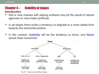
Soil or rock masses with sloping surfaces may be the result of natural
agencies or man-made (artificial).
In all slopes there exists a tendency to degrade to a more stable form
towards the horizontal position.
In this context, instability will be the tendency to move, and failure
actual mass movement.
4.
01/01/2026 4
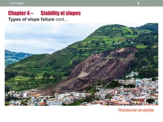
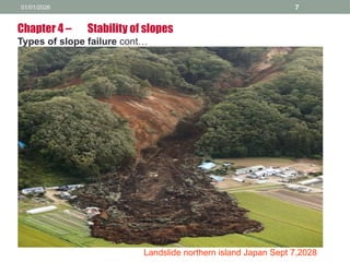
Chapter 4– Stability of slopes
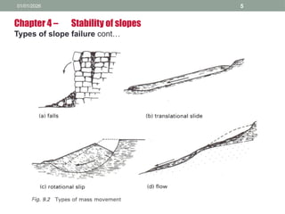
Types of slope failure
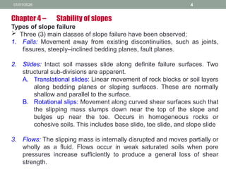
Three (3) main classes of slope failure have been observed;
1. Falls: Movement away from existing discontinuities, such as joints,
fissures, steeply–inclined bedding planes, fault planes.
2. Slides: Intact soil masses slide along definite failure surfaces. Two
structural sub-divisions are apparent.
A. Translational slides: Linear movement of rock blocks or soil layers
along bedding planes or sloping surfaces. These are normally
shallow and parallel to the surface.
B. Rotational slips: Movement along curved shear surfaces such that
the slipping mass slumps down near the top of the slope and
bulges up near the toe. Occurs in homogeneous rocks or
cohesive soils. This includes base slide, toe slide, and slope slide
3. Flows: The slipping mass is internally disrupted and moves partially or
wholly as a fluid. Flows occur in weak saturated soils when pore
pressures increase sufficiently to produce a general loss of shear
strength.
01/01/2026 9
Chapter 4– Stability of slopes
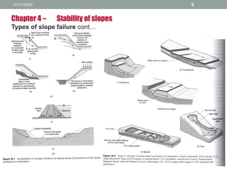
Causes of slope failure
Include;
1) Change in rainfall, drainage conditions (i.e. change in ground pore
water pressure condition).
2) Change in loading condition.
3) Change in surface stability (e.g. Removal of vegetation).
Such changes may occur;
1) Immediately after construction (Short–term is critical).
2) Develop slowly over time (Long–term is critical).
3) Imposed suddenly at any time.
In the analysis of both cut and built slopes it is necessary to consider
both short–term and long–term stability conditions.
10.
01/01/2026 10
Chapter 4– Stability of slopes
Slope failure analysis
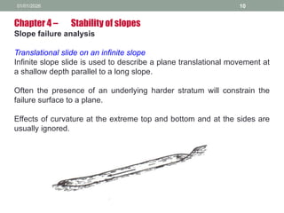
Translational slide on an infinite slope
Infinite slope slide is used to describe a plane translational movement at
a shallow depth parallel to a long slope.
Often the presence of an underlying harder stratum will constrain the
failure surface to a plane.
Effects of curvature at the extreme top and bottom and at the sides are
usually ignored.
11.
01/01/2026 11
Chapter 4– Stability of slopes
Slope failure analysis
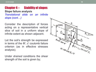
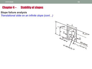
Translational slide on an infinite
slope (cont…)
Consider the description of forces
acting on a representative vertical
slice of soil in a uniform slope of
infinite extent as shown adjacent.
Let the soil’s strength be expressed
in terms of the Φ', c' coulomb failure
criterion (as in effective stresses
analysis).
Under drained conditions the shear
strength of the soil is given by;
12.
01/01/2026 12
Chapter 4– Stability of slopes
Slope failure analysis
Translational slide on an infinite slope
(cont…)
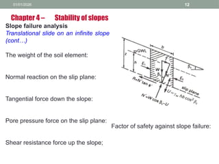
The weight of the soil element:
Normal reaction on the slip plane:
Tangential force down the slope:
Pore pressure force on the slip plane:
Shear resistance force up the slope;
Factor of safety against slope failure:
13.
01/01/2026 13
Slope failureanalysis
Translational slide on an infinite slope (cont…)
Chapter 4 – Stability of slopes
14.
01/01/2026 14
Slope failureanalysis
Translational slide on an infinite slope (cont…)
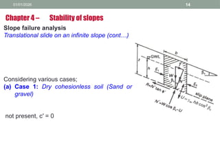
Considering various cases;
(a) Case 1: Dry cohesionless soil (Sand or
gravel)
not present, c′ = 0
Chapter 4 – Stability of slopes
15.
01/01/2026 15
Slope failureanalysis
Translational slide on an infinite slope (cont…)
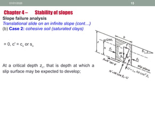
(b) Case 2: cohesive soil (saturated clays)
= 0, c′ = cu or su
At a critical depth zc, that is depth at which a
slip surface may be expected to develop;
Chapter 4 – Stability of slopes
16.
01/01/2026 16
Slope failureanalysis
Translational slide on an infinite slope (cont…)
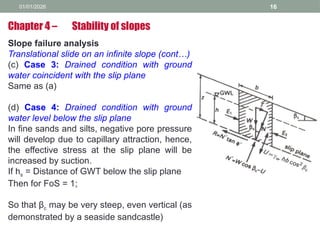
(c) Case 3: Drained condition with ground
water coincident with the slip plane
Same as (a)
(d) Case 4: Drained condition with ground
water level below the slip plane
In fine sands and silts, negative pore pressure
will develop due to capillary attraction, hence,
the effective stress at the slip plane will be
increased by suction.
If hs = Distance of GWT below the slip plane
Then for FoS = 1;
So that βc may be very steep, even vertical (as
demonstrated by a seaside sandcastle)
Chapter 4 – Stability of slopes
17.
01/01/2026 17
Slope failureanalysis
Translational slide on an infinite slope
(cont…)
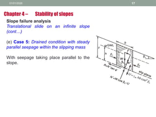
(e) Case 5: Drained condition with steady
parallel seepage within the slipping mass
With seepage taking place parallel to the
slope.
Chapter 4 – Stability of slopes
18.
01/01/2026 18
Slope failuremechanisms in cohesive soils
The most usual methods of providing analysis of stability of slopes in
cohesive soils are based on a consideration of limit plastic
equilibrium.
A limiting plastic equilibrium exists from the moment that a shear slip
movement commences and strain continues at constant stress.
It is firstly necessary to define the geometry of the slip surface.
The mass of soil about to move over this surface is then considered
as a free body in equilibrium.
The forces or moments acting on this free body are evaluated and
those shear forces acting along the slip surface compared with the
available shear resistance offered by the soil.
Chapter 4 – Stability of slopes
19.
01/01/2026 19
Slope failuremechanisms in cohesive
soils (cont…)
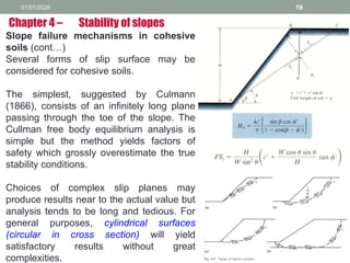
Several forms of slip surface may be
considered for cohesive soils.
The simplest, suggested by Culmann
(1866), consists of an infinitely long plane
passing through the toe of the slope. The
Cullman free body equilibrium analysis is
simple but the method yields factors of
safety which grossly overestimate the true
stability conditions.
Choices of complex slip planes may
produce results near to the actual value but
analysis tends to be long and tedious. For
general purposes, cylindrical surfaces
(circular in cross section) will yield
satisfactory results without great
complexities.
Chapter 4 – Stability of slopes
20.
01/01/2026 20
Slope failuremechanisms in cohesive soils
(cont…)
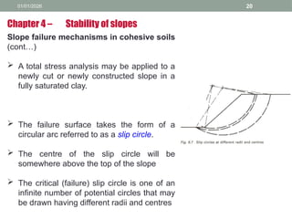
A total stress analysis may be applied to a
newly cut or newly constructed slope in a
fully saturated clay.
The failure surface takes the form of a
circular arc referred to as a slip circle.
The centre of the slip circle will be
somewhere above the top of the slope
The critical (failure) slip circle is one of an
infinite number of potential circles that may
be drawn having different radii and centres
Chapter 4 – Stability of slopes
21.
01/01/2026 21
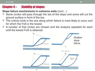
Slope failuremechanisms in cohesive soils (cont…)
Some circles will pass through the toe of the slope and some will cut the
ground surface in front of the toe.
The critical circle is the one along which failure is most likely to occur and
for which the FoS is the lowest.
A number of trial circles are chosen and the analysis repeated for each
until the lowest FoS is obtained.
Chapter 4 – Stability of slopes
Shallow
slope
failure
01/01/2026 23
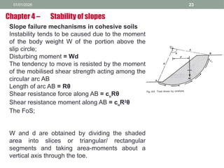
Slope failuremechanisms in cohesive soils
Instability tends to be caused due to the moment
of the body weight W of the portion above the
slip circle;
Disturbing moment = Wd
The tendency to move is resisted by the moment
of the mobilised shear strength acting among the
circular arc AB
Length of arc AB = Rθ
Shear resistance force along AB = cuRθ
Shear resistance moment along AB = cuR2
θ
The FoS;
W and d are obtained by dividing the shaded
area into slices or triangular/ rectangular
segments and taking area-moments about a
vertical axis through the toe.
Chapter 4 – Stability of slopes
24.
01/01/2026 24
Slope failuremechanisms in cohesive
soils (cont…)
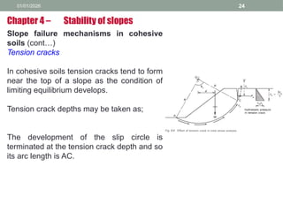
Tension cracks
In cohesive soils tension cracks tend to form
near the top of a slope as the condition of
limiting equilibrium develops.
Tension crack depths may be taken as;
The development of the slip circle is
terminated at the tension crack depth and so
its arc length is AC.
Chapter 4 – Stability of slopes
25.
01/01/2026 25
Slope failuremechanisms in cohesive
soils (cont…)
Tension cracks
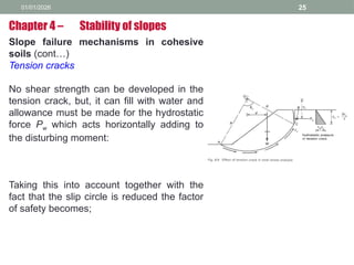
No shear strength can be developed in the
tension crack, but, it can fill with water and
allowance must be made for the hydrostatic
force Pw which acts horizontally adding to
the disturbing moment:
Taking this into account together with the
fact that the slip circle is reduced the factor
of safety becomes;
Chapter 4 – Stability of slopes
26.
01/01/2026 26
Slope failuremechanisms in
cohesive soils (cont…)
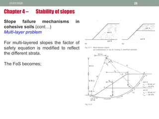
Multi-layer problem
For multi-layered slopes the factor of
safety equation is modified to reflect
the different strata.
The FoS becomes;
Chapter 4 – Stability of slopes
27.
01/01/2026 27
Slope failuremechanisms in cohesive soils (cont…)
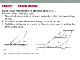
Effect of harder underlying layer
The critical slip circle is constrained to develop only in the weaker layer
above.
All trial circles should be taken through or above the toe.
Stability of soft upper layer must be checked on its own as well as that
of the whole slope.
Chapter 4 – Stability of slopes
28.
01/01/2026 28
Slope failuremechanisms in cohesive soils (cont…)
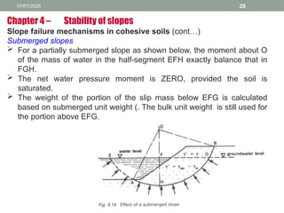
Submerged slopes
For a partially submerged slope as shown below, the moment about O
of the mass of water in the half-segment EFH exactly balance that in
FGH.
The net water pressure moment is ZERO, provided the soil is
saturated.
The weight of the portion of the slip mass below EFG is calculated
based on submerged unit weight (. The bulk unit weight is still used for
the portion above EFG.
Chapter 4 – Stability of slopes
29.
01/01/2026 29
Slope failuremechanisms in cohesive soils (cont…)
Location of the most critical circle
The most critical circle (failure/ slip surface) is the one for which the
calculated factor of safety has the lowest value.
The problem of locating the most critical circle may be approached in
one of two ways;
1) By a process of trial and error, using a reasonable number of ‘trial’
circles and a thoughtful search pattern.
2) By employing an empirical rule to prescribe an assumed critical
circle and setting the limiting factor of safety high enough to allow for
imperfections in the rule.
Chapter 4 – Stability of slopes
30.
01/01/2026 30
Slope failuremechanisms in cohesive soils (cont…)
Location of the most critical circle (cont…)
In the trial and error approach, the method has to allow for variation in
three of the geometric parameters;
i) The position of the centre.
ii) The radius, and the intercept distance in front of the toe.
For acceptable reliability a very large number of trials may have to be
made. The use of computers has made this method more feasible and
reliable.
Chapter 4 – Stability of slopes
31.
01/01/2026 31
Slope failuremechanisms in cohesive soils (cont…)
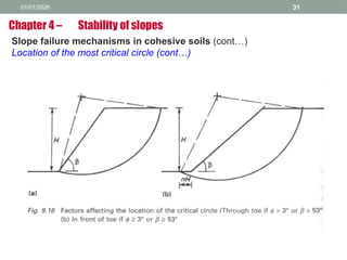
Location of the most critical circle (cont…)
Chapter 4 – Stability of slopes
32.
01/01/2026 32
Slope failuremechanisms in
cohesive soils (cont…)
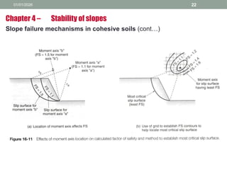
Location of the most critical circle
(cont…)
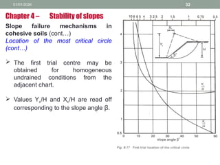
The first trial centre may be
obtained for homogeneous
undrained conditions from the
adjacent chart.
Values Yc/H and Xc/H are read off
corresponding to the slope angle β.
Chapter 4 – Stability of slopes
33.
01/01/2026 33
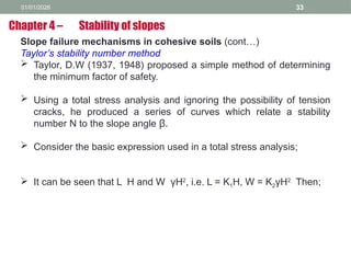
Slope failuremechanisms in cohesive soils (cont…)
Taylor’s stability number method
Taylor, D.W (1937, 1948) proposed a simple method of determining
the minimum factor of safety.
Using a total stress analysis and ignoring the possibility of tension
cracks, he produced a series of curves which relate a stability
number N to the slope angle β.
Consider the basic expression used in a total stress analysis;
It can be seen that L H and W γH2
, i.e. L = K1H, W = K2γH2
Then;
Chapter 4 – Stability of slopes
34.
01/01/2026 34
Slope failuremechanisms in cohesive soils (cont…)
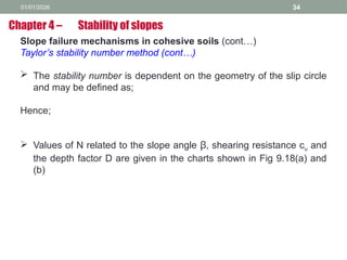
Taylor’s stability number method (cont…)
The stability number is dependent on the geometry of the slip circle
and may be defined as;
Hence;
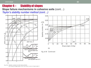
Values of N related to the slope angle β, shearing resistance cu and
the depth factor D are given in the charts shown in Fig 9.18(a) and
(b)
Chapter 4 – Stability of slopes
35.
01/01/2026 35
Chapter 4– Stability of slopes
Slope failure mechanisms in cohesive soils (cont…)
Taylor’s stability number method (cont…)
36.
01/01/2026 36
Chapter 4– Stability of slopes
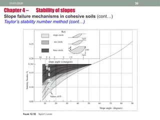
Slope failure mechanisms in cohesive soils (cont…)
Taylor’s stability number method (cont…)
37.
01/01/2026 37
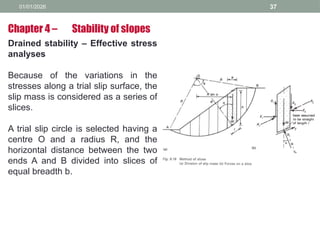
Drained stability– Effective stress
analyses
Because of the variations in the
stresses along a trial slip surface, the
slip mass is considered as a series of
slices.
A trial slip circle is selected having a
centre O and a radius R, and the
horizontal distance between the two
ends A and B divided into slices of
equal breadth b.
Chapter 4 – Stability of slopes
38.
01/01/2026 38
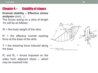
Drained stability– Effective stress
analyses (cont…)
The forces acting on a slice of length
1m will be as follows;
W = the body weight of the slice
N' = the effective normal reacting
force at the base of the slice
T = the shearing force induced along
the base
R1 and R2 = forces imposed on the
sides from adjacent slices – which
may be resolved into:
Chapter 4 – Stability of slopes
39.
01/01/2026 39
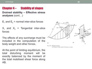
Drained stability– Effective stress
analyses (cont…)
E1 and E2 = normal inter-slice forces
X1 and X2 = Tangential inter-slice
forces
The effects of any surcharge must be
included in the computation of the
body weight and other forces.
At the point of limiting equilibrium, the
total disturbing moment will be
exactly balanced by the moment of
the total mobilised shear force along
AB.
Chapter 4 – Stability of slopes
40.
01/01/2026 40
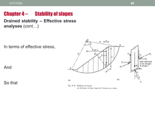
Drained stability– Effective stress
analyses (cont…)
In terms of effective stress,
And
So that
Chapter 4 – Stability of slopes
41.
01/01/2026 41
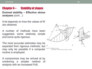
Drained stability– Effective stress
analyses (cont…)
A lot depends on how the values of N'
are obtained.
A number of methods have been
suggested, some relatively simple
and some quite rigorous.
The most accurate estimates may be
expected from rigorous methods, but
may only be possible if a computer
routine is employed.
A compromise may be arrived at by
combining a simpler method of
analysis with an increased FoS.
Chapter 4 – Stability of slopes
42.
01/01/2026 42
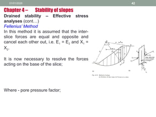
Drained stability– Effective stress
analyses (cont…)
Fellenius’ Method
In this method it is assumed that the inter-
slice forces are equal and opposite and
cancel each other out, i.e. E1 = E2 and X1 =
X2.
It is now necessary to resolve the forces
acting on the base of the slice;
Where - pore pressure factor;
Chapter 4 – Stability of slopes
43.
01/01/2026 43
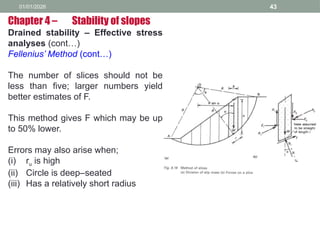
Drained stability– Effective stress
analyses (cont…)
Fellenius’ Method (cont…)
The number of slices should not be
less than five; larger numbers yield
better estimates of F.
This method gives F which may be up
to 50% lower.
Errors may also arise when;
(i) ru is high
(ii) Circle is deep–seated
(iii) Has a relatively short radius
Chapter 4 – Stability of slopes
44.
01/01/2026 44
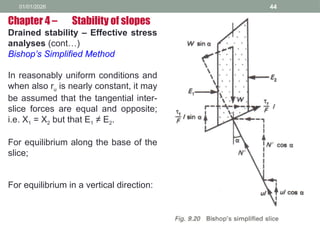
Drained stability– Effective stress
analyses (cont…)
Bishop’s Simplified Method
In reasonably uniform conditions and
when also ru is nearly constant, it may
be assumed that the tangential inter-
slice forces are equal and opposite;
i.e. X1 = X2 but that E1 ≠ E2.
For equilibrium along the base of the
slice;
For equilibrium in a vertical direction:
Chapter 4 – Stability of slopes
45.
01/01/2026 45
Drained stability– Effective stress analyses (cont…)
Bishop’s Simplified Method (cont…)
For equilibrium in a vertical direction:…
Substituting for and N', then rearranging;
The procedure is commenced by assuming a trial value for the F on the
right-hand side and then using an iterative process to converge on the
true value of F for a given circle.
Chapter 4 – Stability of slopes
46.
01/01/2026 46
Drained stability– Effective stress analyses (cont…)
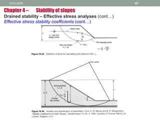
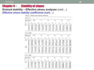
Effective stress stability coefficients (cont…)
A method involving the use of stability coefficients similar to that devised
by Taylor (1948), but in terms of effective stress, was suggested by
Bishop and Morgenstern (1960). The factor of safety is dependent on
five problem variables;
a) Slope angle β
b) Depth factor D (as in Taylor’s method)
c) Angle of shearing resistance Φ′
d) A non – dimensional parameter
e) Pore pressure coefficient ru
The factor of safety varies linearly with ru and is given by
Where m and n are coefficients related to the variables listed above.
Chapter 4 – Stability of slopes
01/01/2026 49
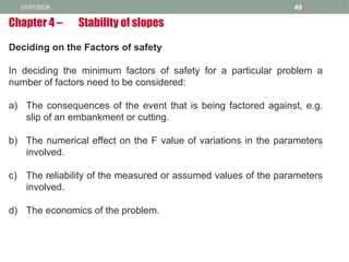
Deciding onthe Factors of safety
In deciding the minimum factors of safety for a particular problem a
number of factors need to be considered:
a) The consequences of the event that is being factored against, e.g.
slip of an embankment or cutting.
b) The numerical effect on the F value of variations in the parameters
involved.
c) The reliability of the measured or assumed values of the parameters
involved.
d) The economics of the problem.
Chapter 4 – Stability of slopes
50.
01/01/2026 50
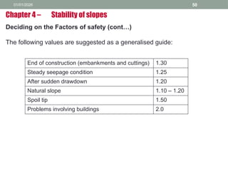
Deciding onthe Factors of safety (cont…)
The following values are suggested as a generalised guide:
Chapter 4 – Stability of slopes
End of construction (embankments and cuttings) 1.30
Steady seepage condition 1.25
After sudden drawdown 1.20
Natural slope 1.10 – 1.20
Spoil tip 1.50
Problems involving buildings 2.0
51.
01/01/2026 51
Improving thefactors of safety of slopes
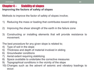
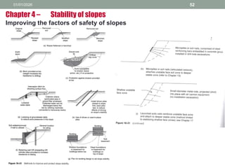
Methods to improve the factor of safety of slopes involve;
1) Reducing the mass or loading that contributes toward sliding
2) Improving the shear strength of the earth in the failure zone
3) Constructing or installing elements that will provide resistance to
movement.
The best procedure for any given slope is related to;
4) Type of soil in the slope
5) Thickness and depth of material involved in sliding
6) Groundwater conditions
7) Aerial extent requiring stabilizing
8) Space available to undertake the corrective measures
9) Topographical conditions in the vicinity of the slope
10) Changes such as the advent of seismic and vibratory loadings to
occur.
Chapter 4 – Stability of slopes


![Geotechnical Engineering-II [Lec #26: Slope Stability]](https://cdn.slidesharecdn.com/ss_thumbnails/26-181125070353-thumbnail.jpg?width=640&height=640&fit=bounds)


