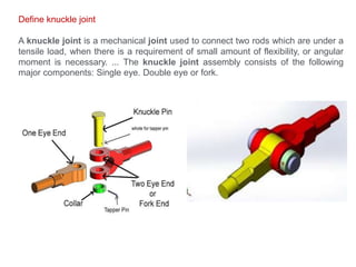
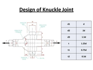
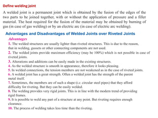
1. The document discusses different types of joints used to connect structural components including knuckle joints, welded joints, and fillet joints.
2. Knuckle joints provide flexibility and angular movement, while welded joints create a permanent connection through fusion. Fillet joints are made by overlapping plates and welding their edges.
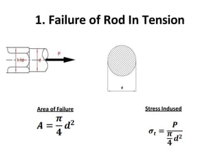
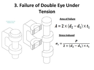
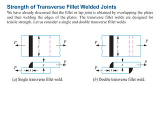
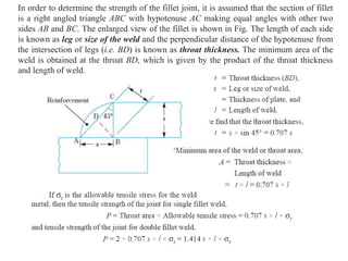
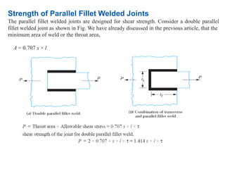
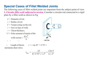
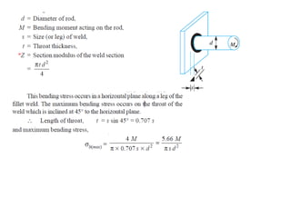
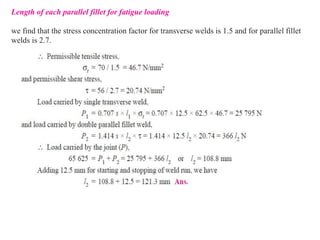
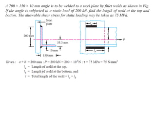
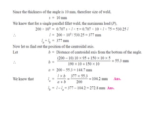
3. The document provides equations to calculate the strength of various welded and fillet joint configurations based on the load applied and permissible stress levels. Examples are given of calculating weld sizes for different joint geometries under static and fatigue loading conditions.