Downloaded 250 times
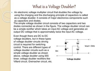

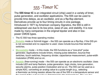
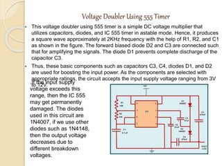
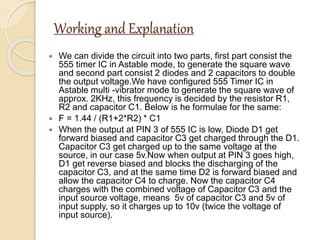
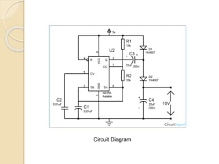
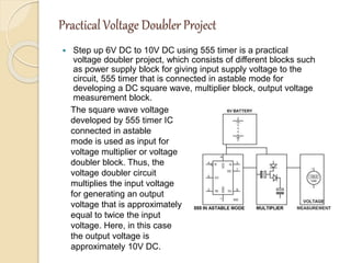

This document describes a voltage doubler circuit that uses a 555 timer integrated circuit. It consists of two capacitors, two diodes, a 555 timer IC, resistors, and a power supply source. The 555 timer generates a square wave that is input to the voltage doubler circuit. The capacitors and diodes in the doubler circuit charge and discharge to output a voltage that is approximately twice the input voltage. The document explains the components, circuit diagram, and working principle of how the 555 timer and voltage doubler combine to multiply the input voltage.