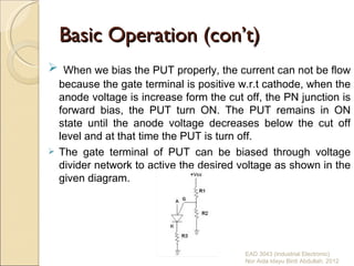
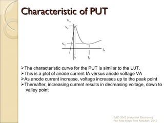
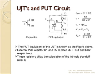
Chapter 2
Programmable Unijunction Transistor (PUT)
Basic Operation


    (a) symbol               (b) construction


 Like the thyristor, its consists of 4 P-N layers .
 Has anode and cathode connected to the first and last layer
  and gate connected to the one of inner layer.
 Not directly interchangeable with conventional UJTs but
  perform a similar function.
 In a proper circuit configuration with two ‘programming’ resistor
  for setting the parameter η, they behave like a conventional
  UJT.
 Example : 2N2067
The only similarity to a UJT is that the PUT can be used in the
  same oscillator to replace the UJT.           EAD 3043 (Industrial Electronic)
                                                      Nor Aida Idayu Binti Abdullah. 2012
Basic Operation (con’t)
 When we bias the PUT properly, the current can not be flow
  because the gate terminal is positive w.r.t cathode, when the
  anode voltage is increase form the cut off, the PN junction is
  forward bias, the PUT turn ON. The PUT remains in ON
  state until the anode voltage decreases below the cut off
  level and at that time the PUT is turn off.
 The gate terminal of PUT can be biased through voltage
  divider network to active the desired voltage as shown in the
  given diagram.


                                         EAD 3043 (Industrial Electronic)
                                         Nor Aida Idayu Binti Abdullah. 2012
Characteristic of PUT


The characteristic curve for the PUT is similar to the UJT.
This is a plot of anode current IA versus anode voltage VA
As anode current increase, voltage increases up to the peak point
Thereafter, increasing current results in decreasing voltage, down to
  valley point


                                              EAD 3043 (Industrial Electronic)
                                              Nor Aida Idayu Binti Abdullah. 2012
Characteristic-(Data Sheet)


                     EAD 3043 (Industrial Electronic)
                     Nor Aida Idayu Binti Abdullah. 2012
Characteristic (con’t)


                         EAD 3043 (Industrial Electronic)
                         Nor Aida Idayu Binti Abdullah. 2012
UJT’s and PUT Circuit


 The PUT equivalent of the UJT is shown as the Figure above.
External PUT resistor R1 and R2 replace UJT RB1 and RB2,
 respectively.
These resistors allow the calculation of the intrinsic standoff
 ratio, η


                                           EAD 3043 (Industrial Electronic)
                                           Nor Aida Idayu Binti Abdullah. 2012
PUT relaxation oscillator


 Figure above shows the PUT version of the unijunction
  relaxation oscillator from the topic UJT before.
 Resistor R charges the capacitor until the peak point then heavy
  conduction moves the operating point down the negative
  resistance slope to the valley point.
 A current spike flows through the cathode during capacitor
 discharge, developing a voltage spike across the cathode resistors.
After capacitor discharge, the operating point resets back to the
 slope up to the peak point                    EAD 3043 (Industrial Electronic)
                                                   Nor Aida Idayu Binti Abdullah. 2012
Summary
 A PUT (programmable unijunction transistor) is a 3-
 terminal 4-layer thyristor acting like a unijunction transistor.
 An external resistor network “programs” η.
The intrinsic standoff ratio is η=R1/(R1+R2) for a PUT;
 substitute RB1 and RB2, respectively, for a unijunction
 transistor. The trigger voltage is determined by η.
Unijunction transistors and programmable unijunction
 transistors are applied to oscillators, timing circuits, and
 thyristor triggering.


                                            EAD 3043 (Industrial Electronic)
                                            Nor Aida Idayu Binti Abdullah. 2012
Example


          EAD 3043 (Industrial Electronic)
          Nor Aida Idayu Binti Abdullah. 2012
Problem: What is the range of suitable values for R, a relaxation
oscillator? The charging resistor must be small enough to supply
enough current to raise the anode to VP the peak point while
charging the capacitor. Once VP is reached, anode voltage
decreases as current increases (negative resistance), which moves
the operating point to the valley. It is the job of the capacitor to
supply the valley current IV. Once it is discharged, the operating point
resets back to the upward slope to the peak point. The resistor must
be large enough so that it will never supply the high valley current IP.
If the charging resistor ever could supply that much current, the
resistor would supply the valley current after the capacitor was
discharged and the operating point would never reset back to the
high resistance condition to the left of the peak point.


                                                EAD 3043 (Industrial Electronic)
                                                Nor Aida Idayu Binti Abdullah. 2012
Solution
 We select the same VBB=10V used for the unijunction
 transistor example. We select values of R1 and R2 so that η
 is about 2/3. We calculate η and VS. The parallel equivalent of
 R1, R2 is RG, which is only used to make selections from
 Table Along with VS=10, the closest value to our 6.3, we find
 VT=0.6V, in Table and calculate VP.


                                            EAD 3043 (Industrial Electronic)
                                            Nor Aida Idayu Binti Abdullah. 2012
We also find IP and IV, the peak and valley currents, respectively in Table
We still need VV, the valley voltage. We used 10% of VBB= 1V, in the
previous unijunction example. Consulting the datasheet, we find the forward
voltage VF=0.8V at IF=50mA. The valley current IV=70µA is much less than
IF=50mA. Therefore, VV must be less than VF=0.8V. How much less? To be
safe we set VV=0V. This will raise the lower limit on the resistor range a
little.


Choosing R > 143k guarantees that the operating point can reset from the
valley point after capacitor discharge. R < 755k allows charging up to VP at
the peak point.


                                                   EAD 3043 (Industrial Electronic)
                                                   Nor Aida Idayu Binti Abdullah. 2012
EAD 3043 (Industrial Electronic)
Nor Aida Idayu Binti Abdullah. 2012
Figure below show the PUT relaxation oscillator with the final resistor
values. A practical application of a PUT triggering an SCR is also shown.
This circuit needs a VBB unfiltered supply (not shown) divided down from
the bridge rectifier to reset the relaxation oscillator after each power zero
crossing. The variable resistor should have a minimum resistor in series
with it to prevent a low pot setting from hanging at the valley point.


                                                    EAD 3043 (Industrial Electronic)
                                                    Nor Aida Idayu Binti Abdullah. 2012
EAD 3043 (Industrial Electronic)
Nor Aida Idayu Binti Abdullah. 2012
EAD 3043 (Industrial Electronic)
Nor Aida Idayu Binti Abdullah. 2012
EAD 3043 (Industrial Electronic)
Nor Aida Idayu Binti Abdullah. 2012
Quiz


       EAD 3043 (Industrial Electronic)
       Nor Aida Idayu Binti Abdullah. 2012
Assignment


             EAD 3043 (Industrial Electronic)
             Nor Aida Idayu Binti Abdullah. 2012

PUT (industrial electronic)

  • 1.
  • 2.
    Basic Operation (a) symbol (b) construction  Like the thyristor, its consists of 4 P-N layers .  Has anode and cathode connected to the first and last layer and gate connected to the one of inner layer.  Not directly interchangeable with conventional UJTs but perform a similar function.  In a proper circuit configuration with two ‘programming’ resistor for setting the parameter η, they behave like a conventional UJT.  Example : 2N2067 The only similarity to a UJT is that the PUT can be used in the same oscillator to replace the UJT. EAD 3043 (Industrial Electronic) Nor Aida Idayu Binti Abdullah. 2012
  • 3.
    Basic Operation (con’t) When we bias the PUT properly, the current can not be flow because the gate terminal is positive w.r.t cathode, when the anode voltage is increase form the cut off, the PN junction is forward bias, the PUT turn ON. The PUT remains in ON state until the anode voltage decreases below the cut off level and at that time the PUT is turn off.  The gate terminal of PUT can be biased through voltage divider network to active the desired voltage as shown in the given diagram. EAD 3043 (Industrial Electronic) Nor Aida Idayu Binti Abdullah. 2012
  • 4.
    Characteristic of PUT Thecharacteristic curve for the PUT is similar to the UJT. This is a plot of anode current IA versus anode voltage VA As anode current increase, voltage increases up to the peak point Thereafter, increasing current results in decreasing voltage, down to valley point EAD 3043 (Industrial Electronic) Nor Aida Idayu Binti Abdullah. 2012
  • 5.
    Characteristic-(Data Sheet) EAD 3043 (Industrial Electronic) Nor Aida Idayu Binti Abdullah. 2012
  • 6.
    Characteristic (con’t) EAD 3043 (Industrial Electronic) Nor Aida Idayu Binti Abdullah. 2012
  • 7.
    UJT’s and PUTCircuit  The PUT equivalent of the UJT is shown as the Figure above. External PUT resistor R1 and R2 replace UJT RB1 and RB2, respectively. These resistors allow the calculation of the intrinsic standoff ratio, η EAD 3043 (Industrial Electronic) Nor Aida Idayu Binti Abdullah. 2012
  • 8.
    PUT relaxation oscillator Figure above shows the PUT version of the unijunction relaxation oscillator from the topic UJT before.  Resistor R charges the capacitor until the peak point then heavy conduction moves the operating point down the negative resistance slope to the valley point.  A current spike flows through the cathode during capacitor discharge, developing a voltage spike across the cathode resistors. After capacitor discharge, the operating point resets back to the slope up to the peak point EAD 3043 (Industrial Electronic) Nor Aida Idayu Binti Abdullah. 2012
  • 9.
    Summary  A PUT(programmable unijunction transistor) is a 3- terminal 4-layer thyristor acting like a unijunction transistor. An external resistor network “programs” η. The intrinsic standoff ratio is η=R1/(R1+R2) for a PUT; substitute RB1 and RB2, respectively, for a unijunction transistor. The trigger voltage is determined by η. Unijunction transistors and programmable unijunction transistors are applied to oscillators, timing circuits, and thyristor triggering. EAD 3043 (Industrial Electronic) Nor Aida Idayu Binti Abdullah. 2012
  • 10.
    Example EAD 3043 (Industrial Electronic) Nor Aida Idayu Binti Abdullah. 2012
  • 11.
    Problem: What isthe range of suitable values for R, a relaxation oscillator? The charging resistor must be small enough to supply enough current to raise the anode to VP the peak point while charging the capacitor. Once VP is reached, anode voltage decreases as current increases (negative resistance), which moves the operating point to the valley. It is the job of the capacitor to supply the valley current IV. Once it is discharged, the operating point resets back to the upward slope to the peak point. The resistor must be large enough so that it will never supply the high valley current IP. If the charging resistor ever could supply that much current, the resistor would supply the valley current after the capacitor was discharged and the operating point would never reset back to the high resistance condition to the left of the peak point. EAD 3043 (Industrial Electronic) Nor Aida Idayu Binti Abdullah. 2012
  • 12.
    Solution We selectthe same VBB=10V used for the unijunction transistor example. We select values of R1 and R2 so that η is about 2/3. We calculate η and VS. The parallel equivalent of R1, R2 is RG, which is only used to make selections from Table Along with VS=10, the closest value to our 6.3, we find VT=0.6V, in Table and calculate VP. EAD 3043 (Industrial Electronic) Nor Aida Idayu Binti Abdullah. 2012
  • 13.
    We also findIP and IV, the peak and valley currents, respectively in Table We still need VV, the valley voltage. We used 10% of VBB= 1V, in the previous unijunction example. Consulting the datasheet, we find the forward voltage VF=0.8V at IF=50mA. The valley current IV=70µA is much less than IF=50mA. Therefore, VV must be less than VF=0.8V. How much less? To be safe we set VV=0V. This will raise the lower limit on the resistor range a little. Choosing R > 143k guarantees that the operating point can reset from the valley point after capacitor discharge. R < 755k allows charging up to VP at the peak point. EAD 3043 (Industrial Electronic) Nor Aida Idayu Binti Abdullah. 2012
  • 14.
    EAD 3043 (IndustrialElectronic) Nor Aida Idayu Binti Abdullah. 2012
  • 15.
    Figure below showthe PUT relaxation oscillator with the final resistor values. A practical application of a PUT triggering an SCR is also shown. This circuit needs a VBB unfiltered supply (not shown) divided down from the bridge rectifier to reset the relaxation oscillator after each power zero crossing. The variable resistor should have a minimum resistor in series with it to prevent a low pot setting from hanging at the valley point. EAD 3043 (Industrial Electronic) Nor Aida Idayu Binti Abdullah. 2012
  • 16.
    EAD 3043 (IndustrialElectronic) Nor Aida Idayu Binti Abdullah. 2012
  • 17.
    EAD 3043 (IndustrialElectronic) Nor Aida Idayu Binti Abdullah. 2012
  • 18.
    EAD 3043 (IndustrialElectronic) Nor Aida Idayu Binti Abdullah. 2012
  • 19.
    Quiz EAD 3043 (Industrial Electronic) Nor Aida Idayu Binti Abdullah. 2012
  • 20.
    Assignment EAD 3043 (Industrial Electronic) Nor Aida Idayu Binti Abdullah. 2012

Editor's Notes