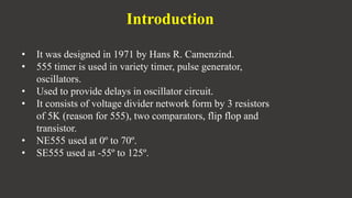
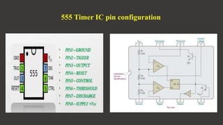
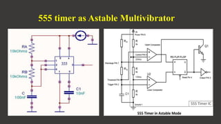
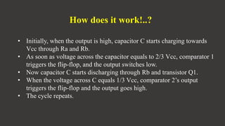
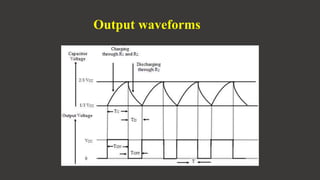
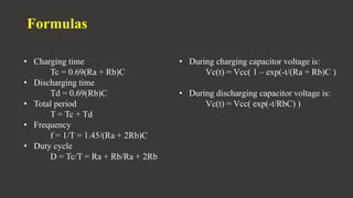
“555 TIMER AS ASTABLE MULTIVIBRATOR”
Presented by,
Chandu L Y
(18BBTEC011)
Department of Electronics and Communication Engineering
1
LINEAR INTEGRATED CIRCUITS
4BEC402
Introduction
• It was designed in 1971 by Hans R. Camenzind.
• 555 timer is used in variety timer, pulse generator,
oscillators.
• Used to provide delays in oscillator circuit.
• It consists of voltage divider network form by 3 resistors
of 5K (reason for 555), two comparators, flip flop and
transistor.
• NE555 used at 0º to 70º.
• SE555 used at -55º to 125º.
555 Timer IC pin configuration
555 timer as Astable Multivibrator
How does it work!..?
• Initially, when the output is high, capacitor C starts charging towards
Vcc through Ra and Rb.
• As soon as voltage across the capacitor equals to 2/3 Vcc, comparator 1
triggers the flip-flop, and the output switches low.
• Now capacitor C starts discharging through Rb and transistor Q1.
• When the voltage across C equals 1/3 Vcc, comparator 2’s output
triggers the flip-flop and the output goes high.
• The cycle repeats.
Output waveforms
Formulas
• Charging time
Tc = 0.69(Ra + Rb)C
• Discharging time
Td = 0.69(Rb)C
• Total period
T = Tc + Td
• Frequency
f = 1/T = 1.45/(Ra + 2Rb)C
• Duty cycle
D = Tc/T = Ra + Rb/Ra + 2Rb
• During charging capacitor voltage is:
Vc(t) = Vcc( 1 – exp(-t/(Ra + Rb)C )
• During discharging capacitor voltage is:
Vc(t) = Vcc( exp(-t/RbC) )
Applications
1.Square wave generation.
2.Pulse position modulation.
3.Pulse train.
4.Frequency modulation.
THANK YOU

555 timer as Astable Multivibrator

  • 1.
    “555 TIMER ASASTABLE MULTIVIBRATOR” Presented by, Chandu L Y (18BBTEC011) Department of Electronics and Communication Engineering 1 LINEAR INTEGRATED CIRCUITS 4BEC402
  • 2.
    Introduction • It wasdesigned in 1971 by Hans R. Camenzind. • 555 timer is used in variety timer, pulse generator, oscillators. • Used to provide delays in oscillator circuit. • It consists of voltage divider network form by 3 resistors of 5K (reason for 555), two comparators, flip flop and transistor. • NE555 used at 0º to 70º. • SE555 used at -55º to 125º.
  • 3.
    555 Timer ICpin configuration
  • 4.
    555 timer asAstable Multivibrator
  • 5.
    How does itwork!..? • Initially, when the output is high, capacitor C starts charging towards Vcc through Ra and Rb. • As soon as voltage across the capacitor equals to 2/3 Vcc, comparator 1 triggers the flip-flop, and the output switches low. • Now capacitor C starts discharging through Rb and transistor Q1. • When the voltage across C equals 1/3 Vcc, comparator 2’s output triggers the flip-flop and the output goes high. • The cycle repeats.
  • 6.
  • 7.
    Formulas • Charging time Tc= 0.69(Ra + Rb)C • Discharging time Td = 0.69(Rb)C • Total period T = Tc + Td • Frequency f = 1/T = 1.45/(Ra + 2Rb)C • Duty cycle D = Tc/T = Ra + Rb/Ra + 2Rb • During charging capacitor voltage is: Vc(t) = Vcc( 1 – exp(-t/(Ra + Rb)C ) • During discharging capacitor voltage is: Vc(t) = Vcc( exp(-t/RbC) )
  • 8.
    Applications 1.Square wave generation. 2.Pulseposition modulation. 3.Pulse train. 4.Frequency modulation.
  • 9.