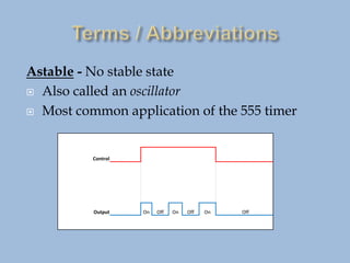
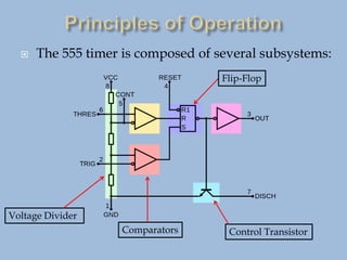
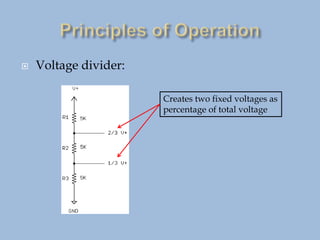
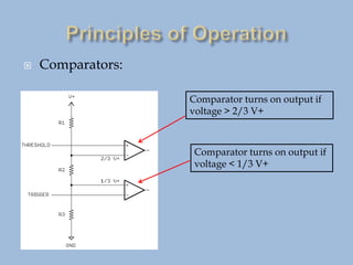
The Principles of Operation and
Applications of a 555 IC Timer
Figure 1 – Signetics 555 timer [1]
 The 555 timer is an Integrated Circuit (I.C.)
containing over 40 discrete components
 It was first manufactured in 1972
 Why study such an old device?
 Designed as a universal timer: can be configured
for many purposes
 Current production of over one billion devices
annually!
Concepts / terms used with the 555 timer
 τ (time constant) = R x C
 Duty Cycle (Time on / Total Time)
 Monostable
 Bistable
 Astable
New Terms
Monostable - one stable state (usually off)
Also called a “One Shot”
Input
Output
Bistable - Two stable states (off / on)
Also called a “Flip-Flop”
Set Input
Reset Input
Output On Off
Astable - No stable state
 Also called an oscillator
 Most common application of the 555 timer
Control
Output On Off On Off On Off
 The 555 timer is composed of several subsystems:
Voltage Divider
Comparators
Flip-Flop
Control Transistor
 Voltage divider:
Creates two fixed voltages as
percentage of total voltage
 Comparators:
Comparator turns on output if
voltage > 2/3 V+
Comparator turns on output if
voltage < 1/3 V+
 External RC Network:
As C charges, the voltage
at the threshold / trigger
point increases.
Capacitor C charges
through Rx and Ry
tau= (Rx + Ry) x C
 Flip Flop / Transistor:
When the bottom comparator
turns on, Q is set
When the top comparator
turns on, Q is set.
Astable Circuit [2]
Astable Circuit [2]
Coffee maker clock/timer [5]
Room light controller [4]
Oscillator
and
Timer
Timer
Oscillator
Vehicle Turn Signals [3]
Varying the duty cycle controls the
average voltage output:
Pulse Width = 10%
Pulse Width = 50%
Pulse Width = 90%
Power drill speed control [7]
Duty Cycle values [6]
Designing an oscillator with the 555 timer requires:
 Calculating Frequency :
𝑓 =
1.44
𝑅1+2𝑅2 × 𝐶
 Calculating Duty Cycle :
𝐷𝐶 =
𝑅1+ 𝑅2
𝑅1+2𝑅2
Determine the frequency and duty cycle of a 555 circuit
with the following values:
R1 = 10.0K R2 = 5.00K C = 4.70uF
𝑓 =
1.44
10×103Ω + 2 × 5×103Ω × 4.7× 10−6𝐹
= 15.4 Hz
𝐷𝐶 =
𝑅1+ 𝑅2
𝑅1+2𝑅2
=
10𝐾Ω+5𝐾Ω
10𝐾Ω+2 ×5𝐾Ω
= 75.0%
 1: http://static.righto.com/images/555/555_operation.png
 2: www.electronics-tutorials.ws/waveforms/555_timer.html
 3: www.aliexpress.com/
 4: www.teambasedapproach.com/03/
 5: www.severin.com/
 6: http://www.lightinthebox.com/
 7: https://www.dewalt.com

555 Timer presentation - 2022.pptx

  • 1.
    The Principles ofOperation and Applications of a 555 IC Timer Figure 1 – Signetics 555 timer [1]
  • 2.
     The 555timer is an Integrated Circuit (I.C.) containing over 40 discrete components  It was first manufactured in 1972  Why study such an old device?  Designed as a universal timer: can be configured for many purposes  Current production of over one billion devices annually!
  • 3.
    Concepts / termsused with the 555 timer  τ (time constant) = R x C  Duty Cycle (Time on / Total Time)  Monostable  Bistable  Astable New Terms
  • 4.
    Monostable - onestable state (usually off) Also called a “One Shot” Input Output
  • 5.
    Bistable - Twostable states (off / on) Also called a “Flip-Flop” Set Input Reset Input Output On Off
  • 6.
    Astable - Nostable state  Also called an oscillator  Most common application of the 555 timer Control Output On Off On Off On Off
  • 7.
     The 555timer is composed of several subsystems: Voltage Divider Comparators Flip-Flop Control Transistor
  • 8.
     Voltage divider: Createstwo fixed voltages as percentage of total voltage
  • 9.
     Comparators: Comparator turnson output if voltage > 2/3 V+ Comparator turns on output if voltage < 1/3 V+
  • 10.
     External RCNetwork: As C charges, the voltage at the threshold / trigger point increases. Capacitor C charges through Rx and Ry tau= (Rx + Ry) x C
  • 11.
     Flip Flop/ Transistor: When the bottom comparator turns on, Q is set When the top comparator turns on, Q is set.
  • 12.
  • 13.
  • 14.
    Coffee maker clock/timer[5] Room light controller [4] Oscillator and Timer Timer Oscillator Vehicle Turn Signals [3]
  • 15.
    Varying the dutycycle controls the average voltage output: Pulse Width = 10% Pulse Width = 50% Pulse Width = 90% Power drill speed control [7] Duty Cycle values [6]
  • 16.
    Designing an oscillatorwith the 555 timer requires:  Calculating Frequency : 𝑓 = 1.44 𝑅1+2𝑅2 × 𝐶  Calculating Duty Cycle : 𝐷𝐶 = 𝑅1+ 𝑅2 𝑅1+2𝑅2
  • 17.
    Determine the frequencyand duty cycle of a 555 circuit with the following values: R1 = 10.0K R2 = 5.00K C = 4.70uF
  • 18.
    R1 = 10.0KR2 = 5.00K C = 4.70uF 𝑓 = 1.44 10×103Ω + 2 × 5×103Ω × 4.7× 10−6𝐹 = 15.4 Hz 𝐷𝐶 = 𝑅1+ 𝑅2 𝑅1+2𝑅2 = 10𝐾Ω+5𝐾Ω 10𝐾Ω+2 ×5𝐾Ω = 75.0%
  • 19.
     1: http://static.righto.com/images/555/555_operation.png 2: www.electronics-tutorials.ws/waveforms/555_timer.html  3: www.aliexpress.com/  4: www.teambasedapproach.com/03/  5: www.severin.com/  6: http://www.lightinthebox.com/  7: https://www.dewalt.com