Downloaded 16 times
![Working of project
This project uses voltage multiplier circuit in multistage
using a no of silicon diodes (D1-D8) and a set of
electrolytic capacitors of 2 no’s of 100mf/400V connected
in series.
Thus 16 capacitor of 100mf/400V are used for 8 stage
voltage multiplication.
Thus if the input is 230v rms the output will be
approximately [sqrt 2 x 230 x 8 = appx 2.5kv].
In order to measure this voltage a potential divider
arrangement comprising of 10resistors in series is made
such that the voltage across 1 resistor is 2.5/10=250V,
Which can be easily read by any standard meter to indicate
that the full voltage is approximately 2.5kV.
500k resistors are connected across each pair of capacitors
to discharge them automatically after use, it will prevent
from high voltage electric shock.](https://image.slidesharecdn.com/highvoltagemodule-170225112156/85/High-voltage-module-8-320.jpg)

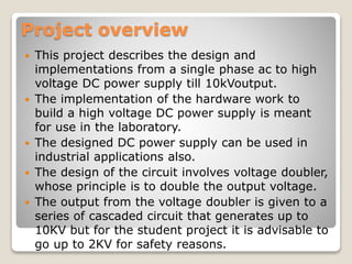
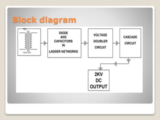
The document details a project that designs a high voltage DC power supply, converting single-phase AC to an output of up to 10 kV, with a recommended safe output of 2 kV for student use. It employs a voltage doubler circuit using multiple silicon diodes and electrolytic capacitors for voltage multiplication. The project includes safety measures such as a potential divider for voltage measurement and resistors for discharging capacitors.