Downloaded 1,463 times
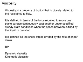
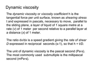


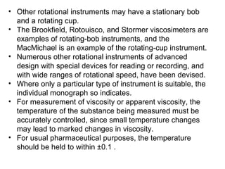
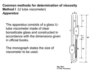


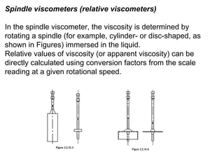


Viscosity is a measure of a liquid's resistance to flow. It is defined as the shear stress divided by the rate of shear strain. There are several methods to measure viscosity, including using capillary tubes, rotating viscometers, and falling ball viscometers. The measurement involves determining the time required for liquid to flow through a capillary or for a ball to fall between marks in a viscometer tube, from which the dynamic viscosity in mPa·s can be calculated. Viscosity measurements require controlling the temperature accurately, usually within 0.1°C.