Download as PDF, PPTX
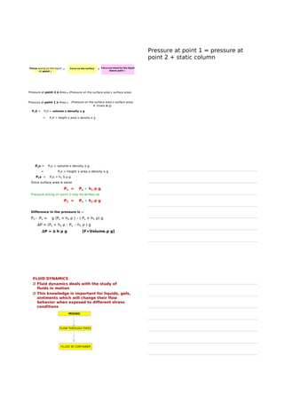
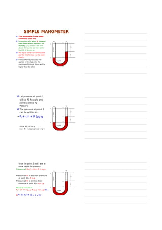
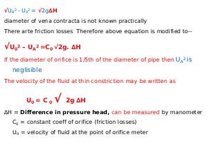
![P1s = P2s + volume x density x g
= P2s + height x area x density x g
P1s = P2s + h1 S ρ g
Since surface area is same
P1 = Ps + h1 ρ g
Pressure acting on point 2 may be written as
P2 = Ps + h2 ρ g
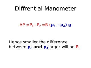
Difference in the pressure is --
P2 - P1 = g (Ps + h2 ρ ) – ( Ps + h1 ρ) g
∆P = (Ps + h2 ρ – Ps - h1 ρ ) g
∆P = ∆ h ρ g [F=Volume.ρ g]](https://image.slidesharecdn.com/fluidflowsb-160915165853/85/Flow-of-Fluids-18-320.jpg)
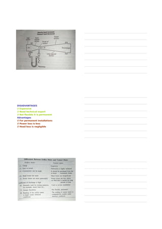
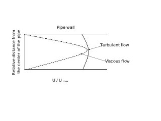
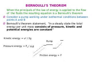
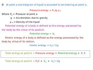
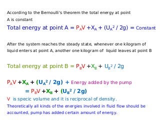
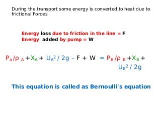
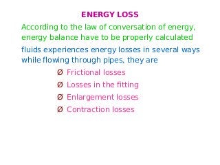
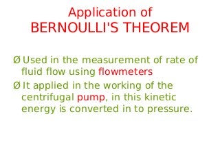
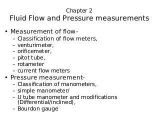
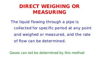
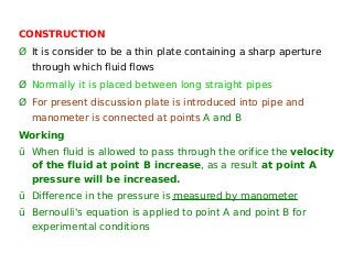
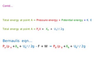
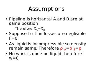
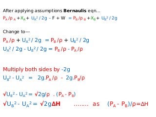
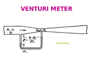
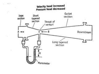

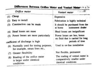
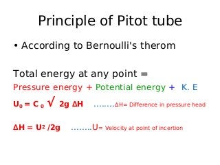
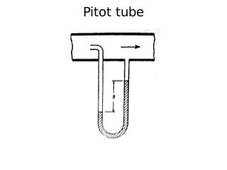
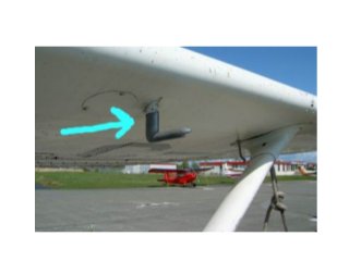
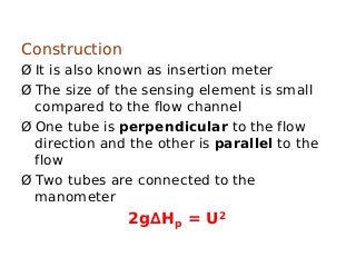
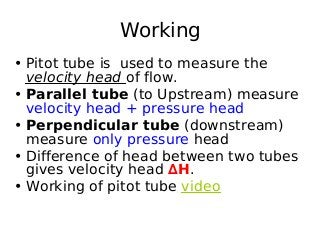
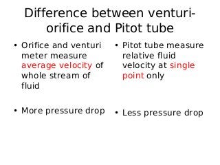
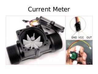

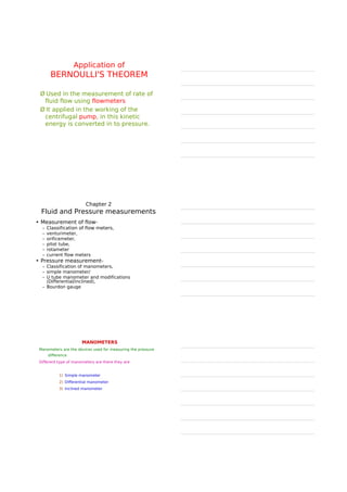
The document provides an overview of fluid flow and its measurement, including key concepts such as fluid properties, fluid dynamics, and various fluid measurement devices like manometers and flowmeters. It discusses principles like Bernoulli's theorem, laminar and turbulent flow, and the Reynolds number, which is crucial in predicting the flow behavior of fluids. Additionally, it mentions specific instruments like the orifice meter, venturimeter, and pitot tube, with explanations of their functions and applications in pressure and flow measurement.


