Data Flow Diagrams
•Data flow diagram: is a graphical modeling tool to
depict the flow of data through a system and the
work or processing performed by that system.
– What’s the system doing?
• Use a limited number of symbols.
• Do not depict management or operational elements
of a system.
Data Flow Diagram(DFD)
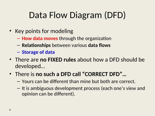
• Key points for modeling
– How data moves through the organization
– Relationships between various data flows
– Storage of data
• There are no FIXED rules about how a DFD should be
developed…
• There is no such a DFD call “CORRECT DFD”…
– Yours can be different than mine but both are correct.
– It is ambiguous development process (each one’s view and
opinion can be different).
4
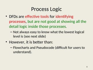
Process Logic
• DFDsare effective tools for identifying
processes, but are not good at showing all the
detail logic inside those processes.
– Not always easy to know what the lowest logical
level is (see next slide)
• However, it is better than:
– Flowcharts and Pseudocode (difficult for users to
understand).
6
7.
7
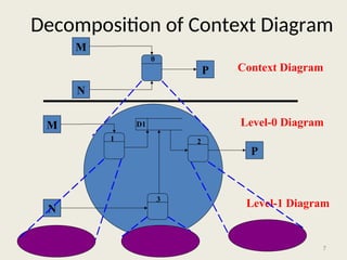
Decomposition of ContextDiagram
M
N
P
M
N
P
Context Diagram
Level-0 Diagram
Level-1 Diagram
1 2
3
0
D1
8.
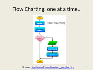
Flow Charting: oneat a time..
8
Source: http://www.rff.com/flowchart_samples.htm
9.
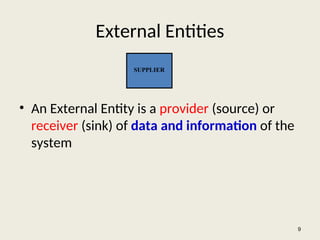
External Entities
• AnExternal Entity is a provider (source) or
receiver (sink) of data and information of the
system
9
SUPPLIER
10.
External Entities …
•As scope changes, external agents can become
processes, and vice versa.
• Almost always one of the following:
– Office, department, division inside the business but
outside the system scope.
– An external organization or agency.
– Another business or another system.
– One of system’s end-users or managers
10
11.
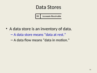
Data Stores
• Adata store is an inventory of data.
– A data store means “data at rest.”
– A data flow means “data in motion.”
11
D1 Accounts Receivable
12.
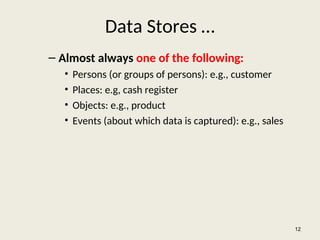
Data Stores …
–Almost always one of the following:
• Persons (or groups of persons): e.g., customer
• Places: e.g, cash register
• Objects: e.g., product
• Events (about which data is captured): e.g., sales
12
13.
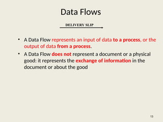
Data Flows
• AData Flow represents an input of data to a process, or the
output of data from a process.
• A Data Flow does not represent a document or a physical
good: it represents the exchange of information in the
document or about the good
13
DELIVERY SLIP
14.
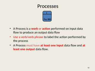
Processes
• A Processis a work or action performed on input data
flow to produce an output data flow
• Use a verb/verb phrase to label the action performed by
the process
• A Process must have at least one input data flow and at
least one output data flow.
14
1
Pay Bill
15.
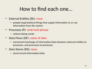
How to findeach one…
• External Entities (EE): noun
– people/organizations/things that supply information to or use
information from the system
• Processes (P): verb/verb phrase
– actions/doing words
• Data Flows (DF): name of data
– movement/exchange of information/data between external entities to
processes, and processes to processes
• Data Stores (DS): noun
– store/record information/data
15
16.
Example for findingeach one…
• A student (EE/DS) sends in an application form (DF)
containing their personal details, and their desired course .
The university (EE) checks (P) that the course (EE/DS) is
available. If the course is available and the student is enrolled
(P) in the course, the university confirms (P) the enrolment by
sending a confirmation letter (DF) that they are registered (P)
for the course to the student. Or if the course is unavailable
the student is sent a rejection letter (DF).
16
17.
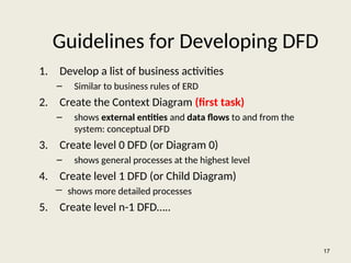
Guidelines for DevelopingDFD
1. Develop a list of business activities
– Similar to business rules of ERD
2. Create the Context Diagram (first task)
– shows external entities and data flows to and from the
system: conceptual DFD
3. Create level 0 DFD (or Diagram 0)
– shows general processes at the highest level
4. Create level 1 DFD (or Child Diagram)
― shows more detailed processes
5. Create level n-1 DFD…..
17
18.
18
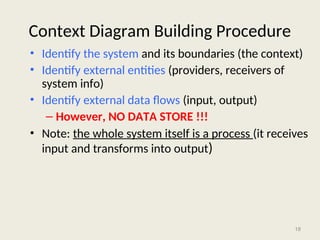
Context Diagram BuildingProcedure
• Identify the system and its boundaries (the context)
• Identify external entities (providers, receivers of
system info)
• Identify external data flows (input, output)
– However, NO DATA STORE !!!
• Note: the whole system itself is a process (it receives
input and transforms into output)
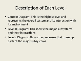
Description of EachLevel
• Context Diagram: This is the highest level and
represents the overall system and its interaction with
its environment
• Level 0 Diagram: This shows the major subsystems
and their interactions
• Level x Diagram: Shows the processes that make up
each of the major subsystems
21.
Practice Context Diagram
•Go back to the class website
• Download and open
• “Context Diagram Practice”
21
22.
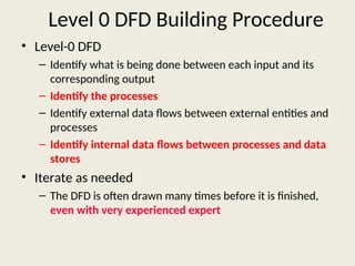
Level 0 DFDBuilding Procedure
• Level-0 DFD
– Identify what is being done between each input and its
corresponding output
– Identify the processes
– Identify external data flows between external entities and
processes
– Identify internal data flows between processes and data
stores
• Iterate as needed
– The DFD is often drawn many times before it is finished,
even with very experienced expert
23.
23
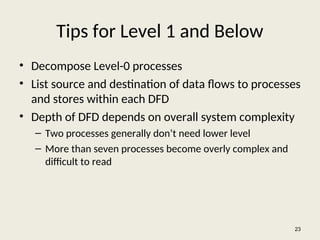
Tips for Level1 and Below
• Decompose Level-0 processes
• List source and destination of data flows to processes
and stores within each DFD
• Depth of DFD depends on overall system complexity
– Two processes generally don’t need lower level
– More than seven processes become overly complex and
difficult to read
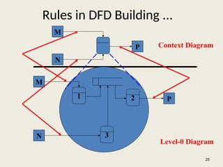
Rules in DFDBuilding ...
25
M
N
P
1 2
3
M
N
P
Context Diagram
Level-0 Diagram
26.
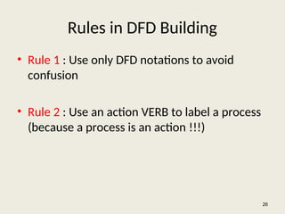
Rules in DFDBuilding
• Rule 1 : Use only DFD notations to avoid
confusion
• Rule 2 : Use an action VERB to label a process
(because a process is an action !!!)
26
27.
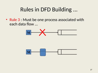
Rules in DFDBuilding ...
• Rule 3 : Must be one process associated with
each data flow …
27
M
M
28.
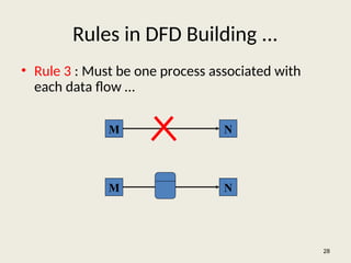
Rules in DFDBuilding ...
• Rule 3 : Must be one process associated with
each data flow …
28
M N
M N
29.
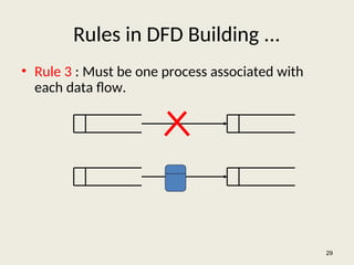
Rules in DFDBuilding ...
• Rule 3 : Must be one process associated with
each data flow.
29
30.
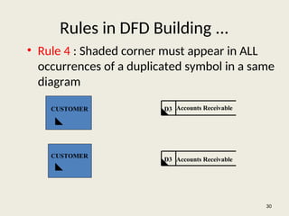
Rules in DFDBuilding ...
• Rule 4 : Shaded corner must appear in ALL
occurrences of a duplicated symbol in a same
diagram
30
CUSTOMER
CUSTOMER
D3
D3
Accounts Receivable
Accounts Receivable
31.
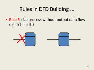
Rules in DFDBuilding ...
• Rule 5 : No process without output data flow
(black hole !!!)
31
32.
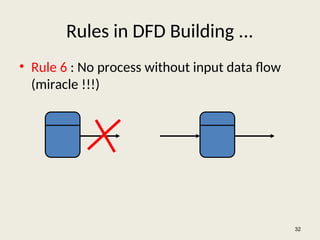
Rules in DFDBuilding ...
• Rule 6 : No process without input data flow
(miracle !!!)
32
33.
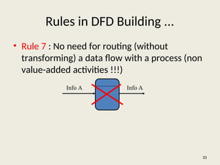
Rules in DFDBuilding ...
• Rule 7 : No need for routing (without
transforming) a data flow with a process (non
value-added activities !!!)
33
Info A Info A
34.
Rules in DFDBuilding ...
• Rule 8 : Identical input, output data flows for
parent and child processes (but the child
processes can have their own throughputs)
– See the picture in next slide
34
35.
35
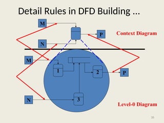
Detail Rules inDFD Building ...
M
N
P
1 2
3
M
N
P
Context Diagram
Level-0 Diagram
36.
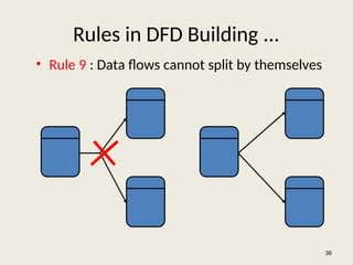
Rules in DFDBuilding ...
• Rule 9 : Data flows cannot split by themselves
36
37.
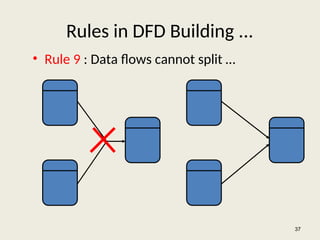
Rules in DFDBuilding ...
• Rule 9 : Data flows cannot split …
37
38.
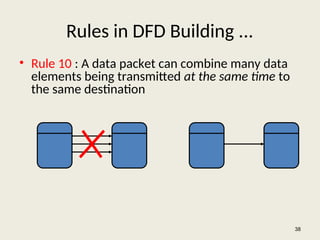
Rules in DFDBuilding ...
• Rule 10 : A data packet can combine many data
elements being transmitted at the same time to
the same destination
38
39.
Rules in DFDBuilding ...
• Rule 11 : Double-headed arrows are forbidden
[in- flow (update) and out-flow (extract info)
of a data store are different]
39
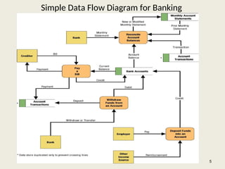
Editor's Notes
#5 Teaching Notes
We have found it useful to walk through this first DFD. Don’t be alarmed if students take exception to some of the oversimplification of the illustrated problem—it can actually contribute to the learning experience.
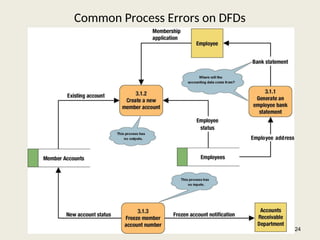
#24 Teaching Notes
Idea: Correct this diagram as an in-class exercise.
3.1.1: To correct the diagram, a data flow, ACCOUNTING DATA, should be added from the data store, MEMBER ACCOUNTS, to process 3.1.1.
3.1.2: To fix the black hole, we might add an output data flow called NEW MEMBER ACCOUNT from process 3.1.2 to the data store MEMBER ACCOUNTS.
3.1.3: To fix the miracle, you would need to at least add a data flow such as ACCOUNTING DATA from the data store, MEMBER ACCOUNTS, to process 3.1.3. In all likelihood, you also need some type of triggering data flow, such as ACCOUNT FREEZE AUTHORIZATION, from a new external agent, such ACCOUNTING DEPARTMENT, to process 3.1 3.


![Rules in DFD Building ...
• Rule 11 : Double-headed arrows are forbidden
[in- flow (update) and out-flow (extract info)
of a data store are different]
39](https://image.slidesharecdn.com/dfdtool-250707061301-8d3e6b1c/85/Data-Flow-Diagram-Design-and-Analysses-39-320.jpg)


![제 23회 보아즈(BOAZ) 빅데이터 컨퍼런스 - [MBOAX] : ABSA를 활용한 소비자 반응 분석 기반 운영 효율화 대시보드 설계](https://cdn.slidesharecdn.com/ss_thumbnails/3-1boaz23rdconferencemboax-260203102709-9d519923-thumbnail.jpg?width=640&height=640&fit=bounds)

