Downloaded 275 times
![FLOW PROCESS J2006/7/7
Example 7.2
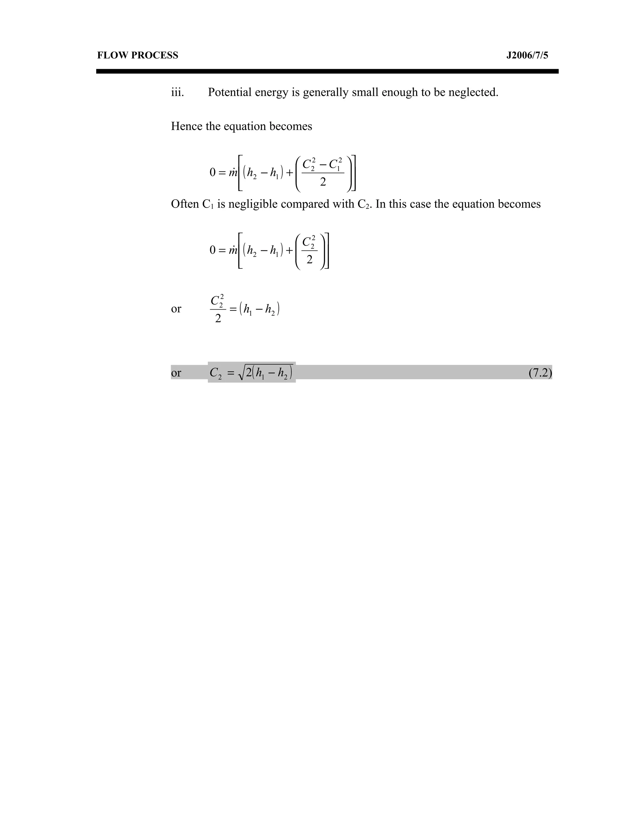
Fluid with a specific enthalpy of 2800 kJ/kg enters a horizontal nozzle with
negligible velocity at the rate of 14 kg/s. At the outlet from the nozzle the
specific enthalpy and specific volume of the fluid are 2250 kJ/kg and
1.25 m3/kg respectively. Assuming an adiabatic flow, determine the required
outlet area of the nozzle.
Solution to Example 7.2
The steady flow energy equation gives
C 2 − C12
Q − W = m ( h2 − h1 ) + 2
+ ( gZ 2 − gZ 1 )
2
When applied to the nozzle, this becomes
C 2 − C12
0 = m ( h2 − h1 ) + 2
2
Since the inlet C1 is negligible, this may be written as
C 22 = 2( h1 − h2 )
= √ [2(2800 – 22500]
= 1050 m/s
Applying the equation of continuity at outlet gives
A2C2
m=
v2
A2 x 1050 m/s
14 kg/s =
1.25 m 3 /kg
A2 = 0.01668 m2](https://image.slidesharecdn.com/unit7-120701123706-phpapp02/75/Unit7-7-2048.jpg)

![FLOW PROCESS J2006/7/17
Feedback to Activity 7B
900
7.3 Data : m =
= 0.25 kg/s
3600
h1 = 300 kJ/kg
h2 = 500 kJ/kg
C1= 10 m/s
C2= 15 m/s
Q = 2500 W = 2.5 kW
W=?
The steady flow energy equation gives
C 2 − C12
Q − W = m ( h2 − h1 ) + 2
+ ( gZ 2 − gZ 1 )
2
Neglecting the change in Potential energy since it is negligible
C 2 − C12
Q − W = m ( h2 − h1 ) + 2
+
2
15 2 − 10 2
-W = 0.25 [( 500- 300) + ( )] + 2.5
2 x10 3
-W = 52.5 kW](https://image.slidesharecdn.com/unit7-120701123706-phpapp02/75/Unit7-17-2048.jpg)

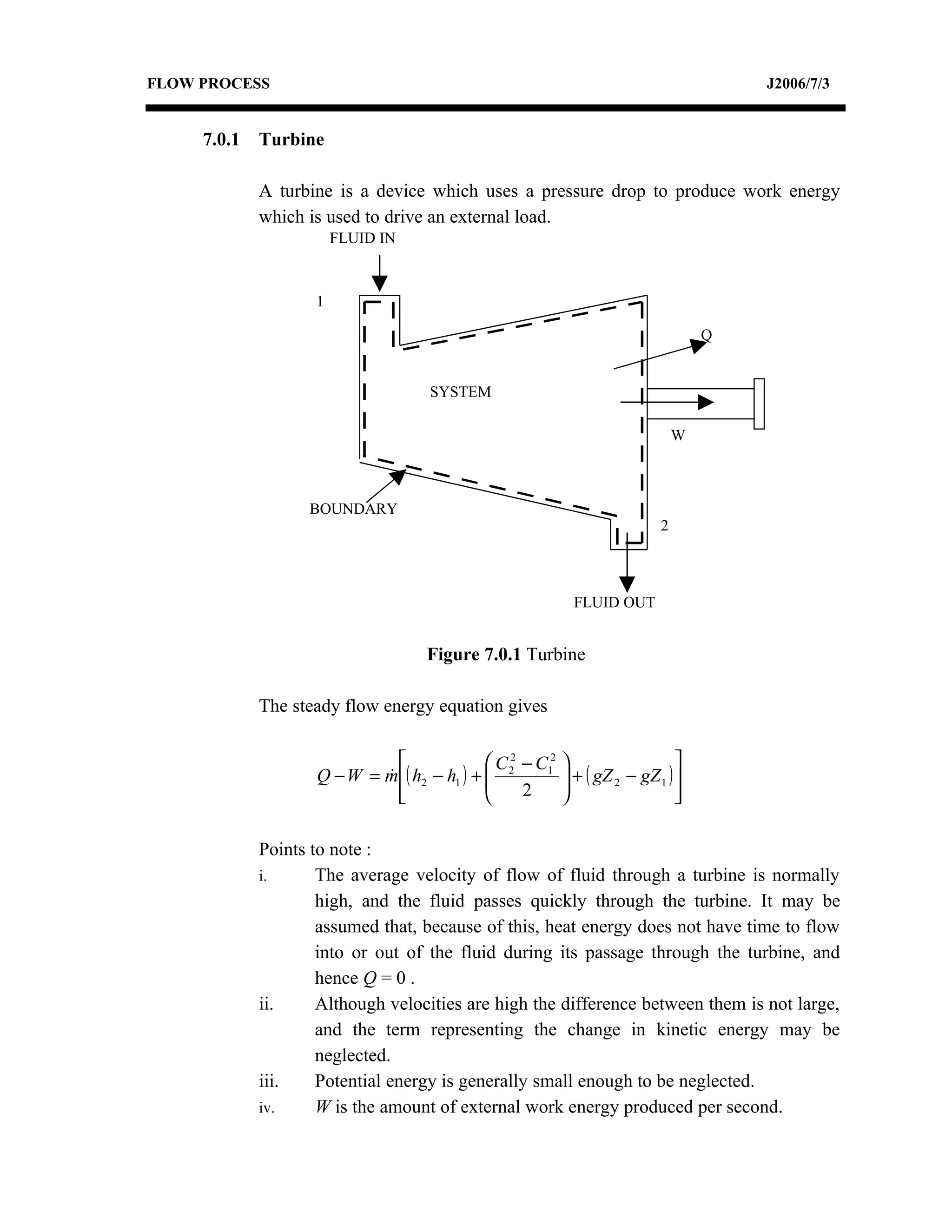
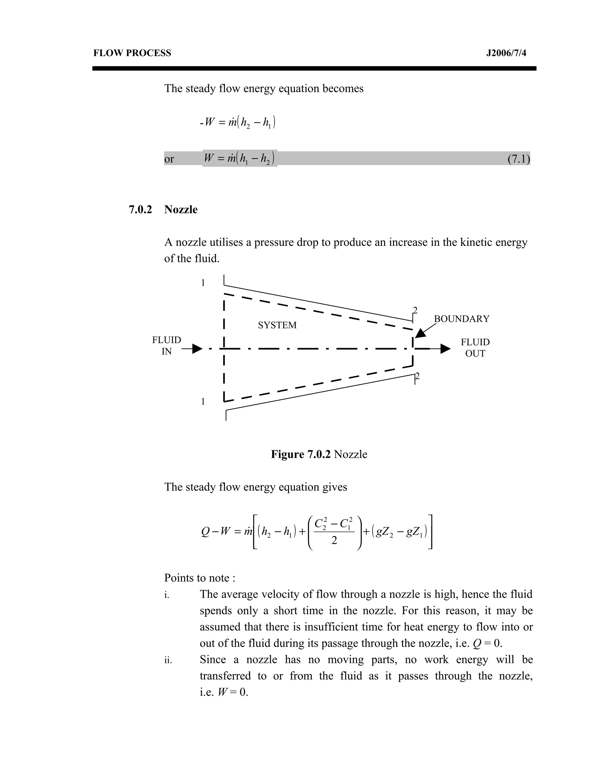
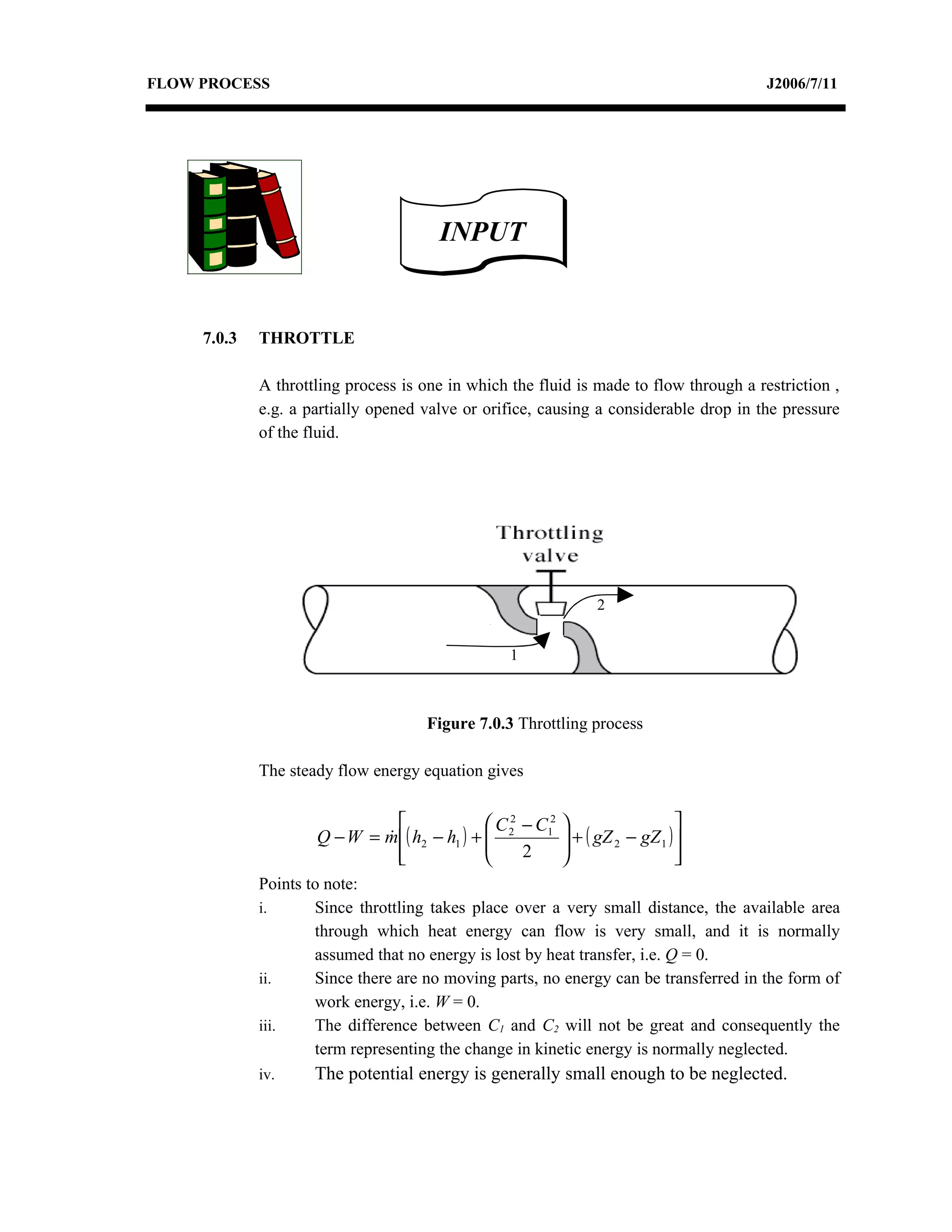
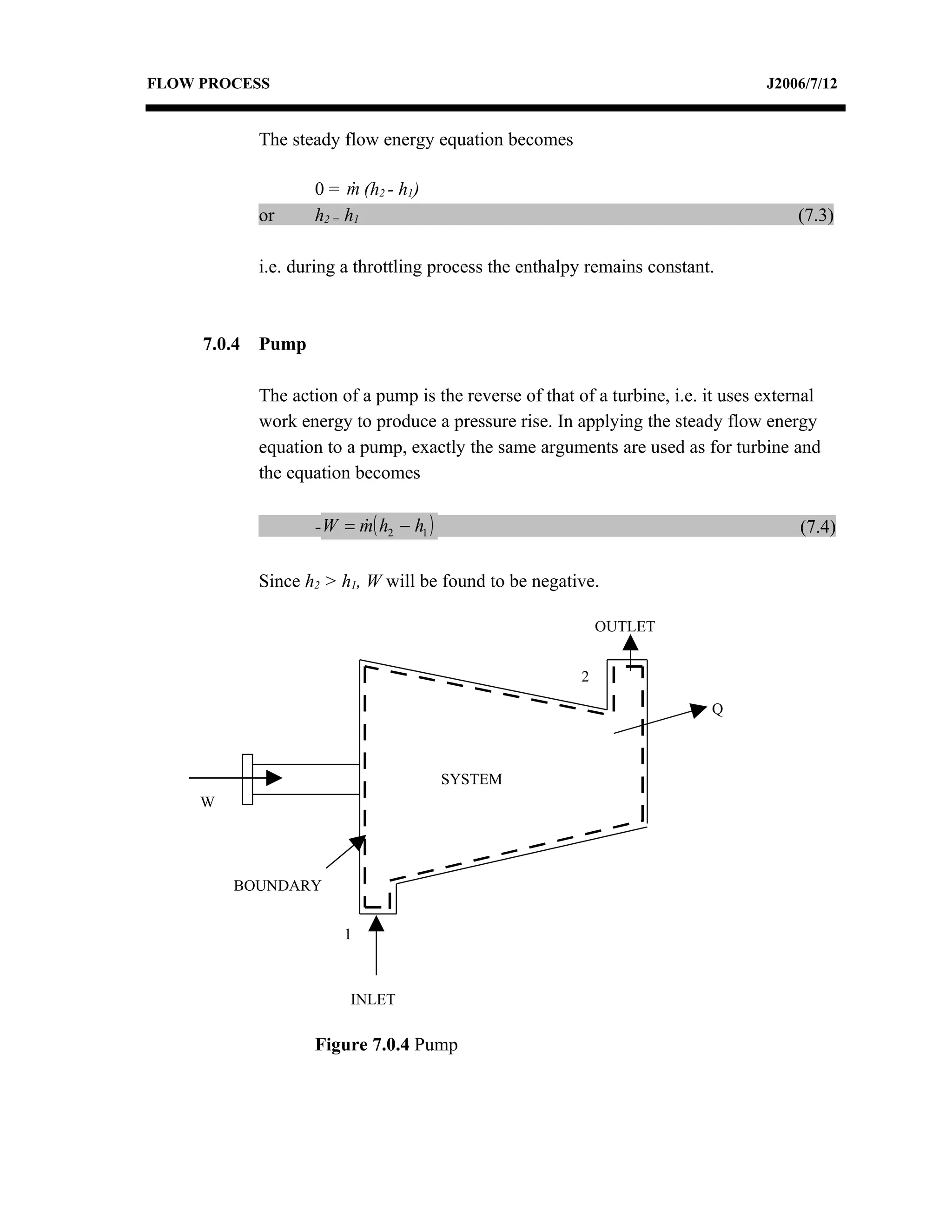
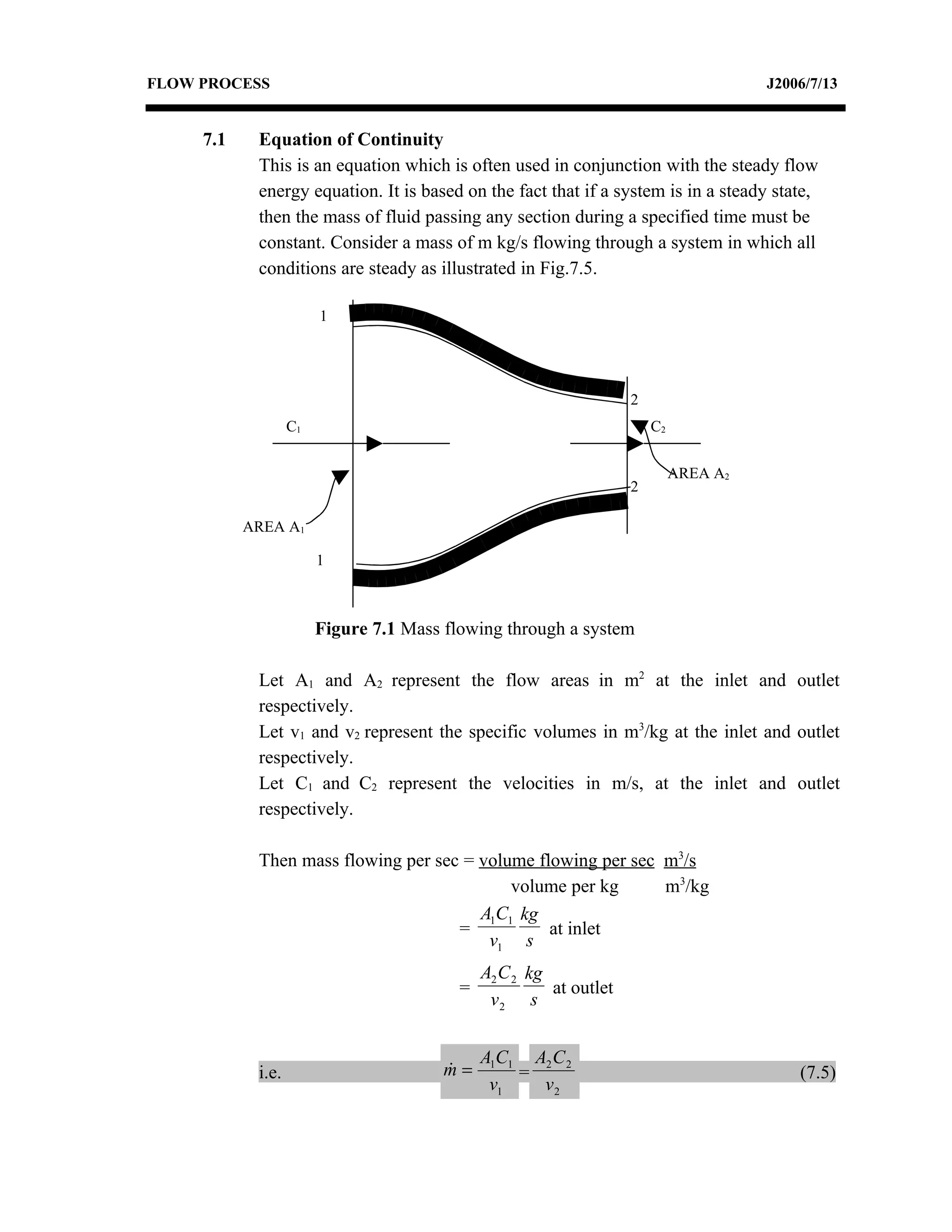
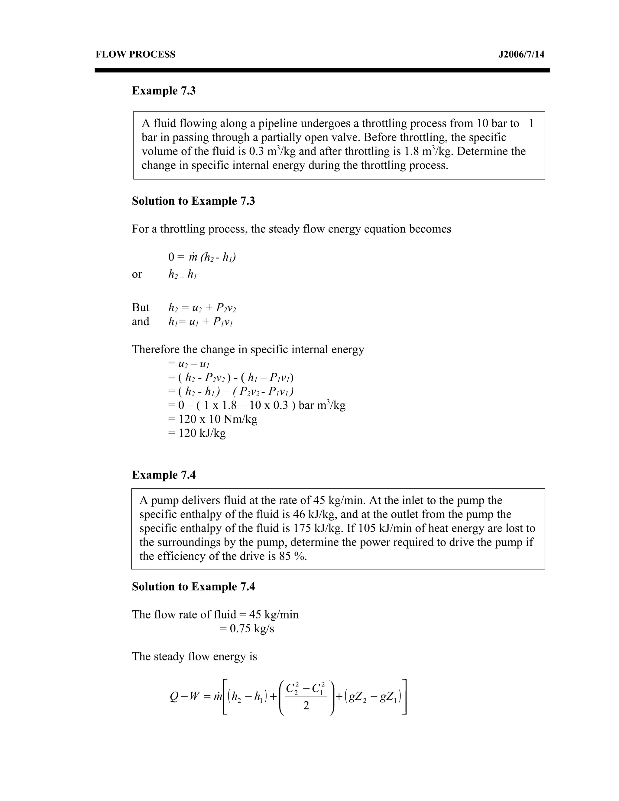
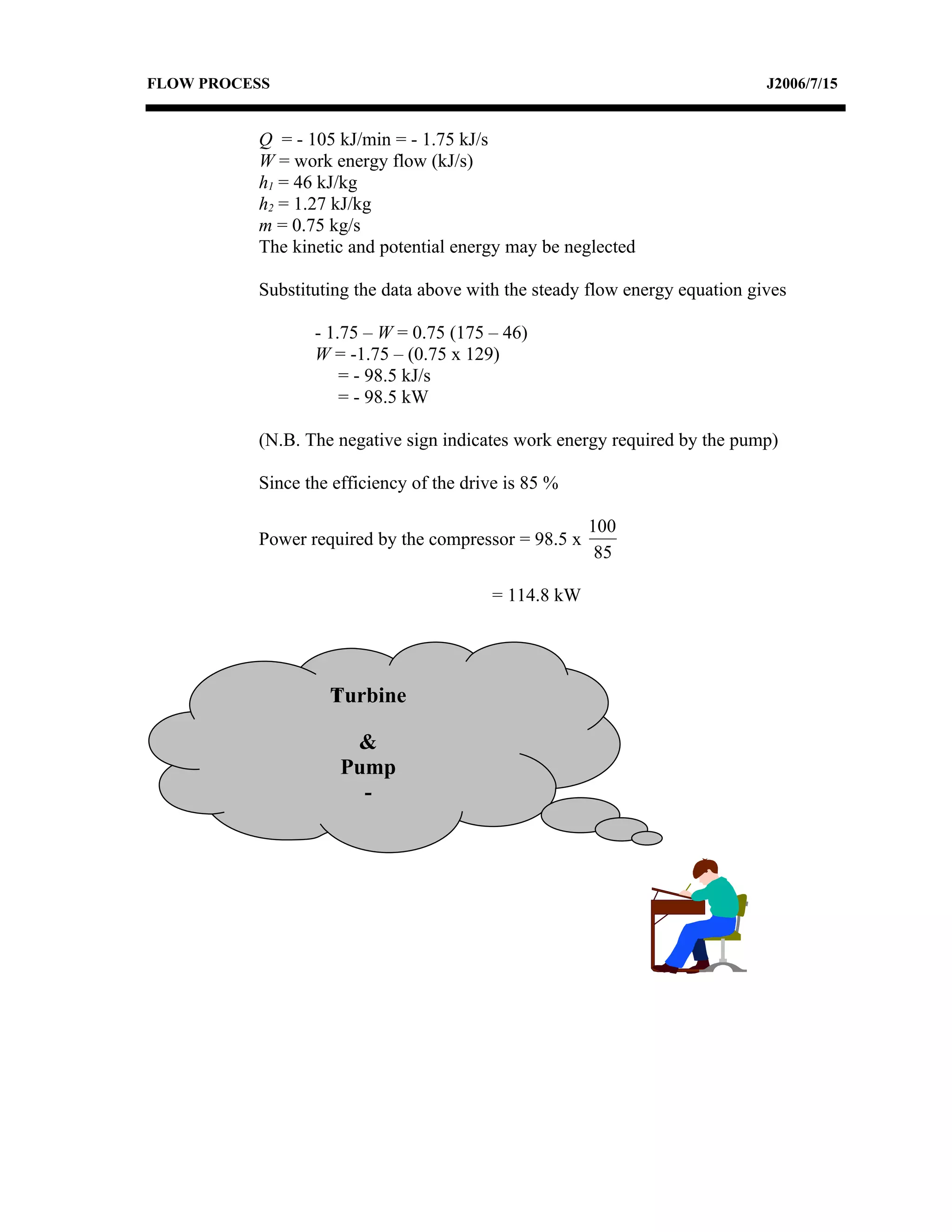
The document discusses the application of the steady flow energy equation to various flow processes including turbines, nozzles, throttles, and pumps. It explains that for turbines, the steady flow energy equation relates the enthalpy drop of the fluid to the work produced. For nozzles, the equation shows the relationship between the enthalpy drop and the kinetic energy increase of the fluid. For throttles, the equation indicates that the enthalpy remains constant. And for pumps, the equation relates the enthalpy rise to the work input into the system. Examples are provided to demonstrate how to use the steady flow energy equation to analyze different flow processes.


![Vibe Coding vs. Spec-Driven Development [Free Meetup]](https://cdn.slidesharecdn.com/ss_thumbnails/vibecodingvsspecdrivendevelopment-251209105622-43f455e7-thumbnail.jpg?width=640&height=640&fit=bounds)


![Coded Agents – with UiPath SDK + LangGraph [Virtual Hands-on Workshop]](https://cdn.slidesharecdn.com/ss_thumbnails/codedagentsdeck-251215155422-5497c599-thumbnail.jpg?width=640&height=640&fit=bounds)