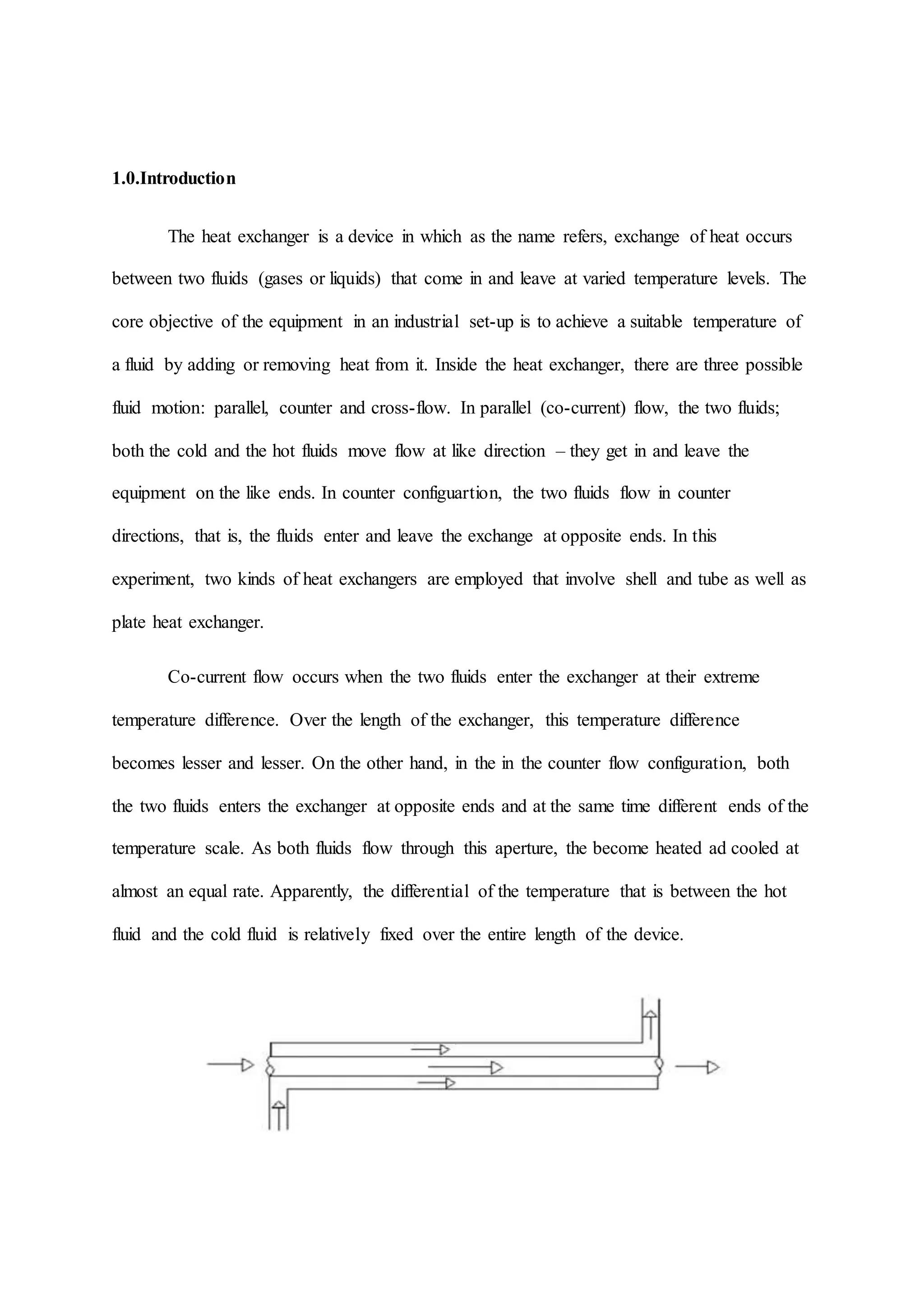
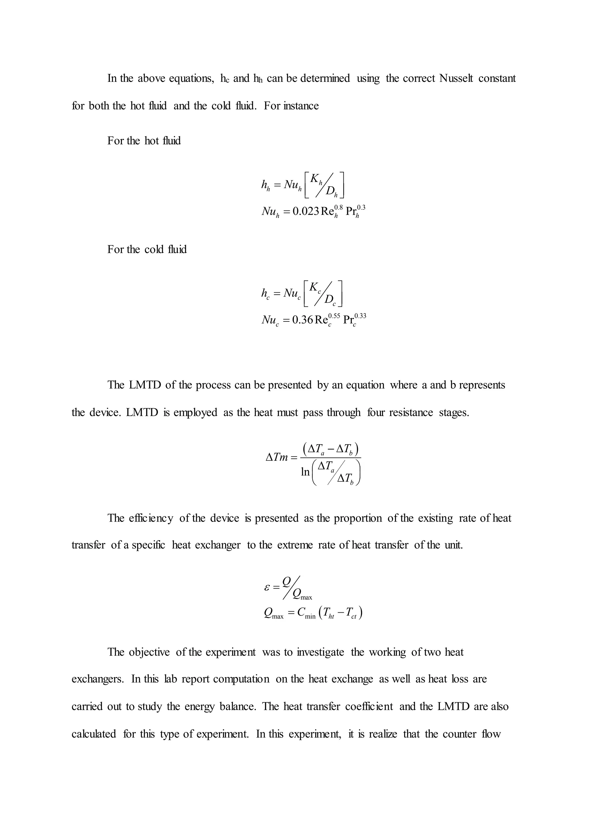
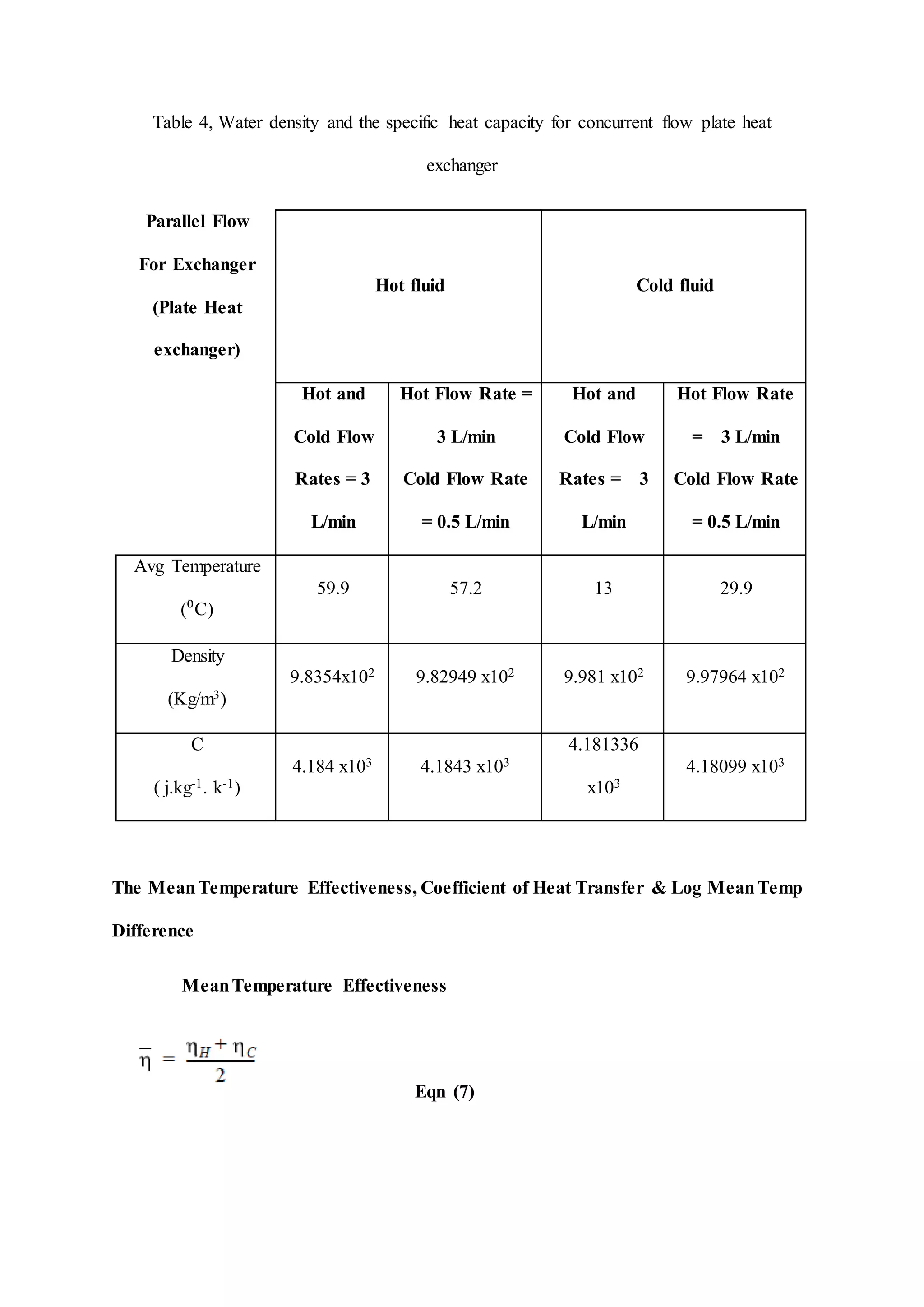
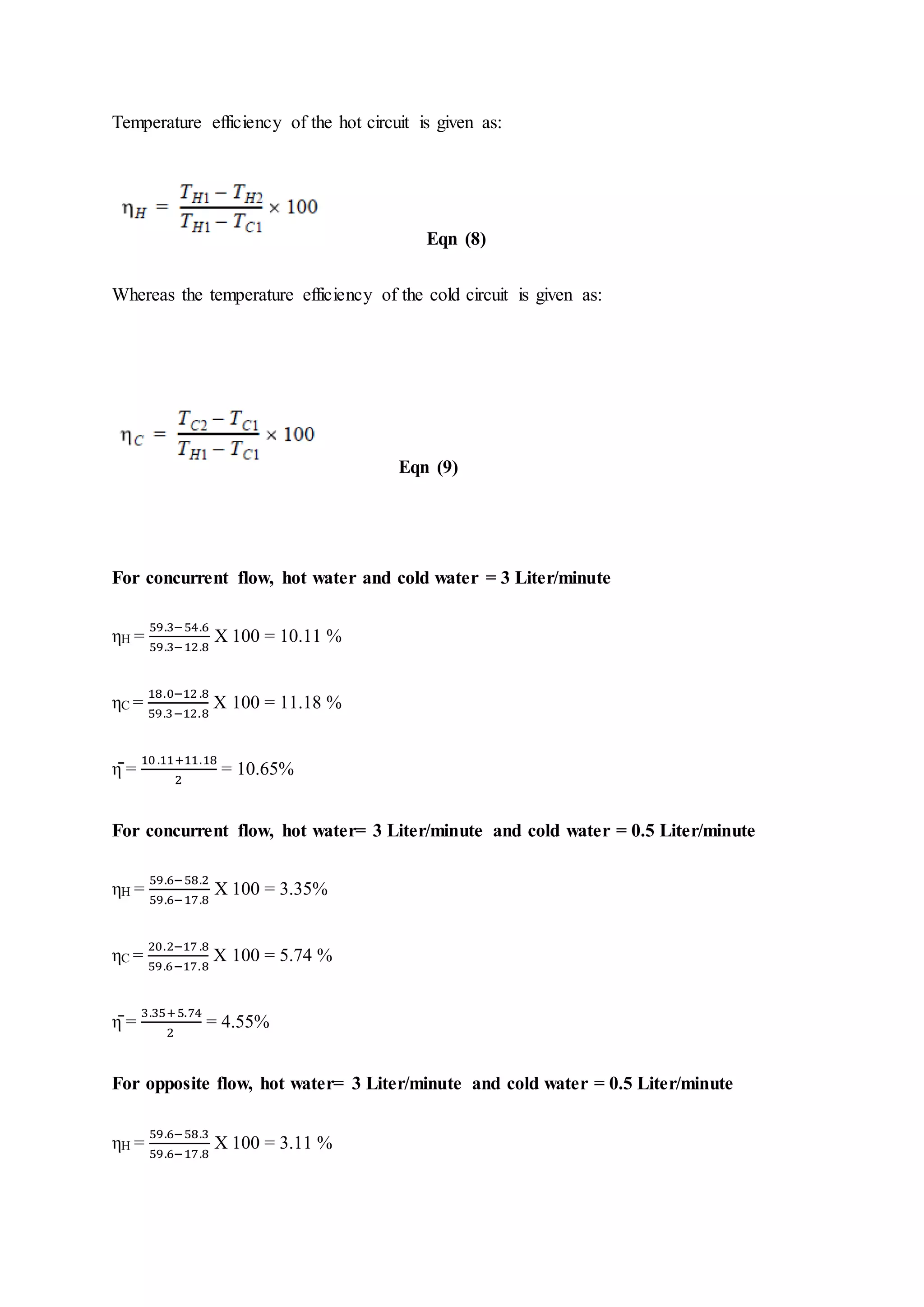
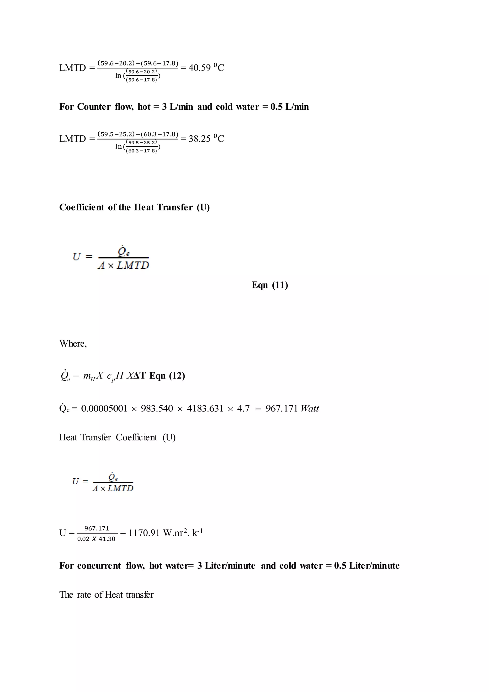
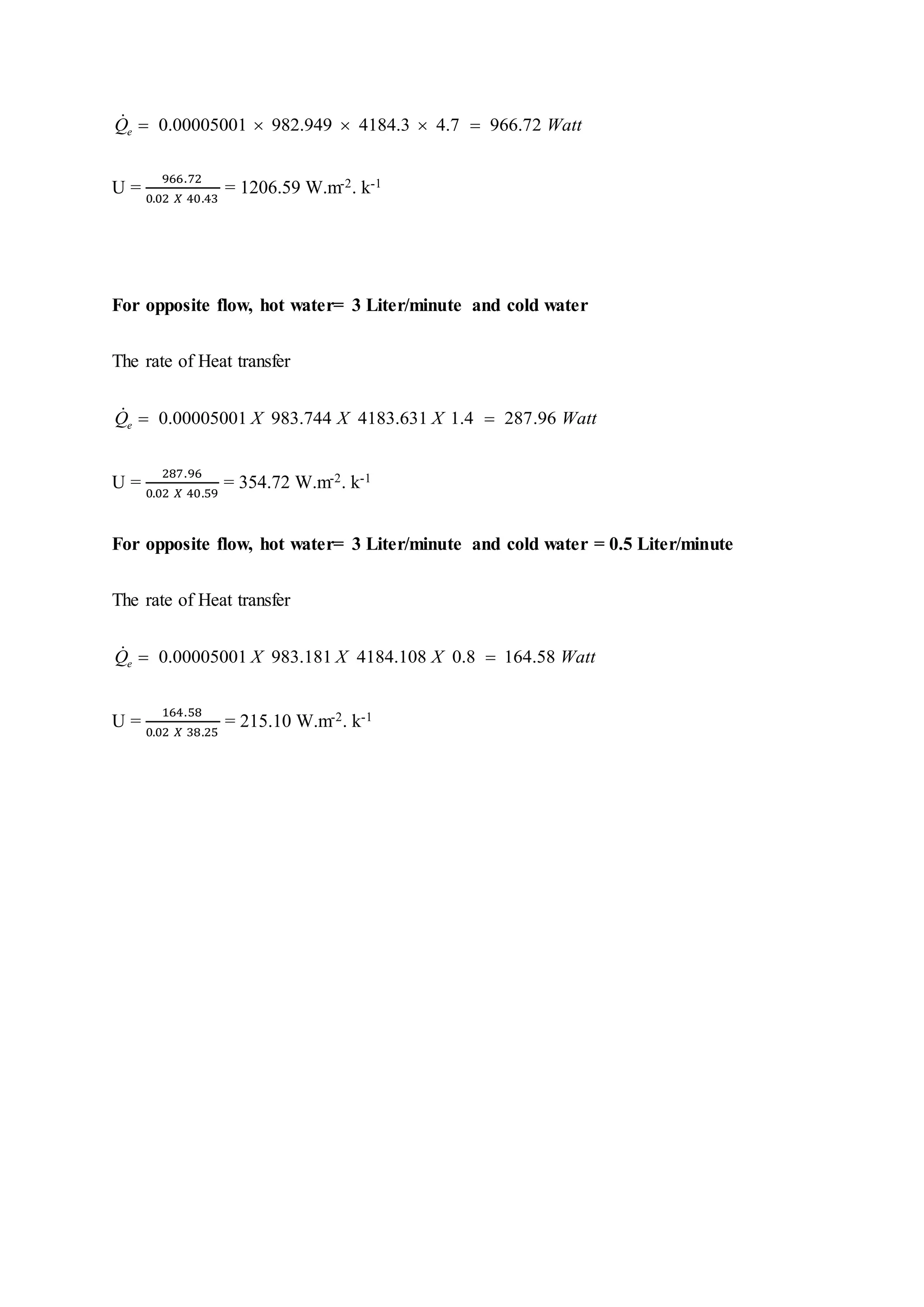
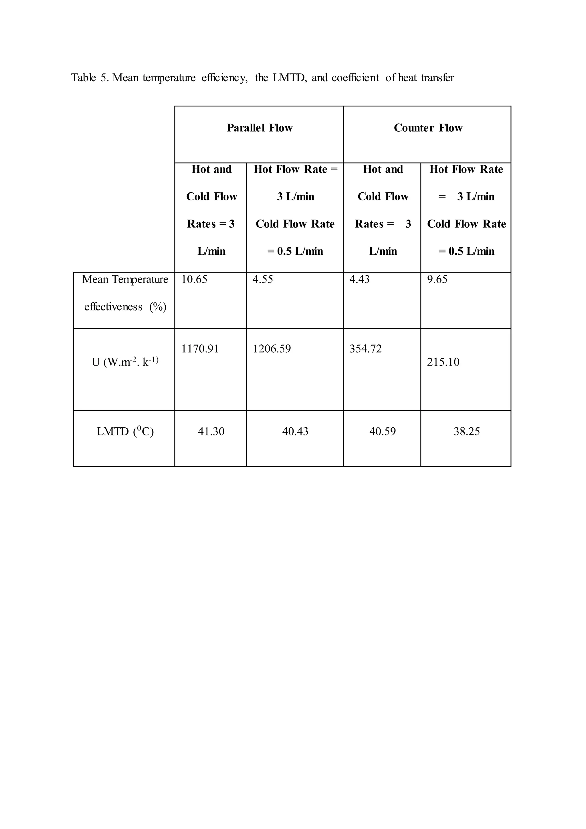
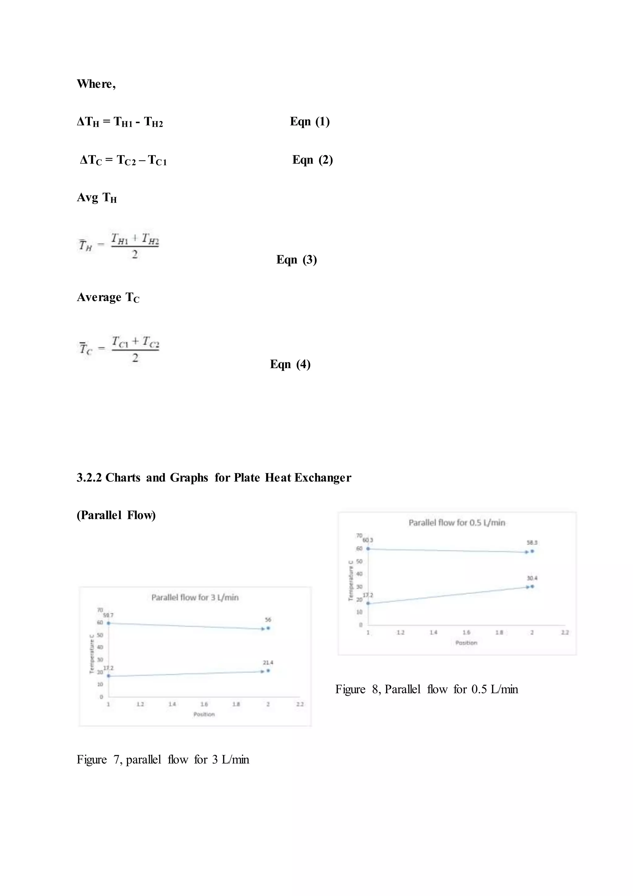
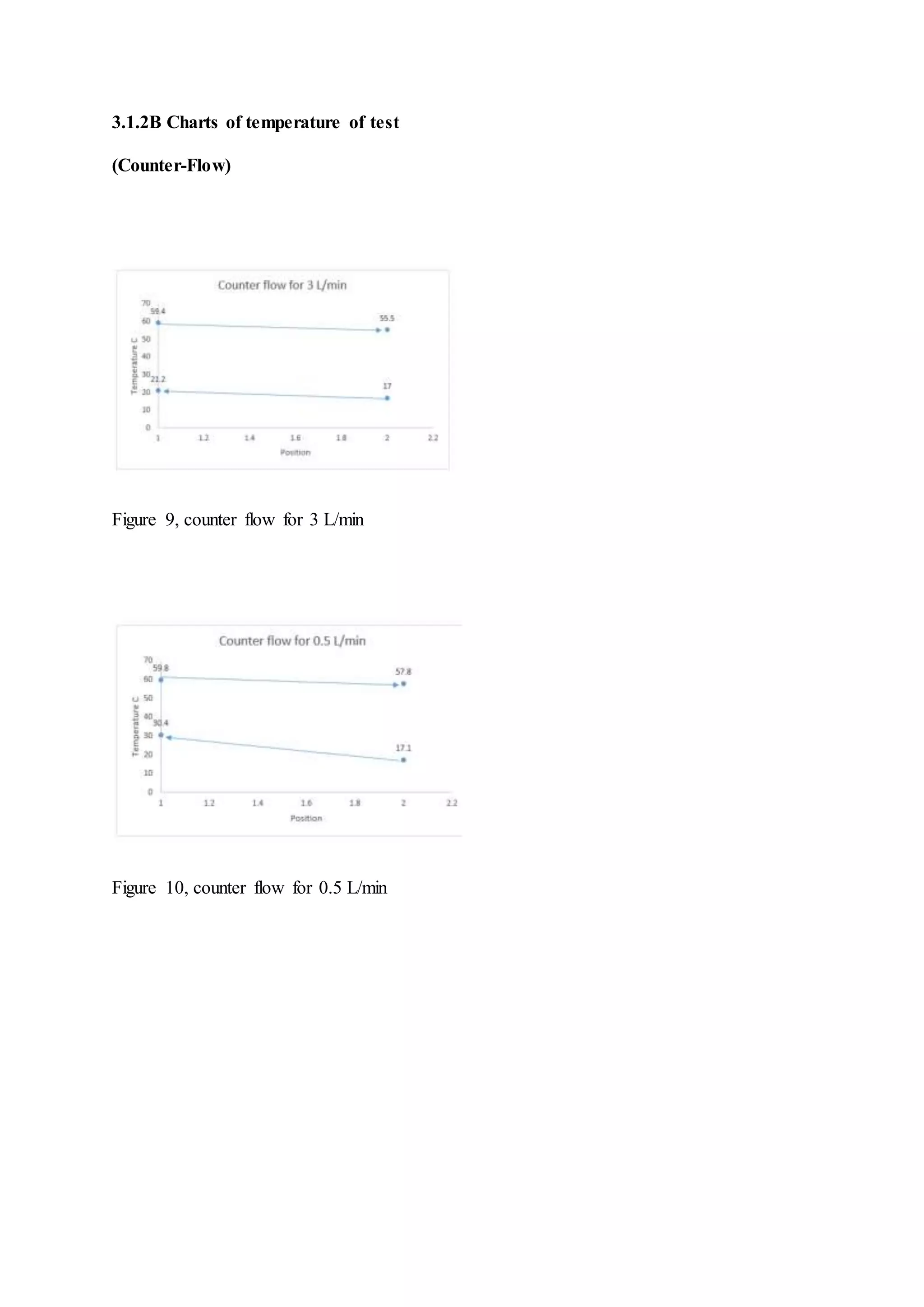
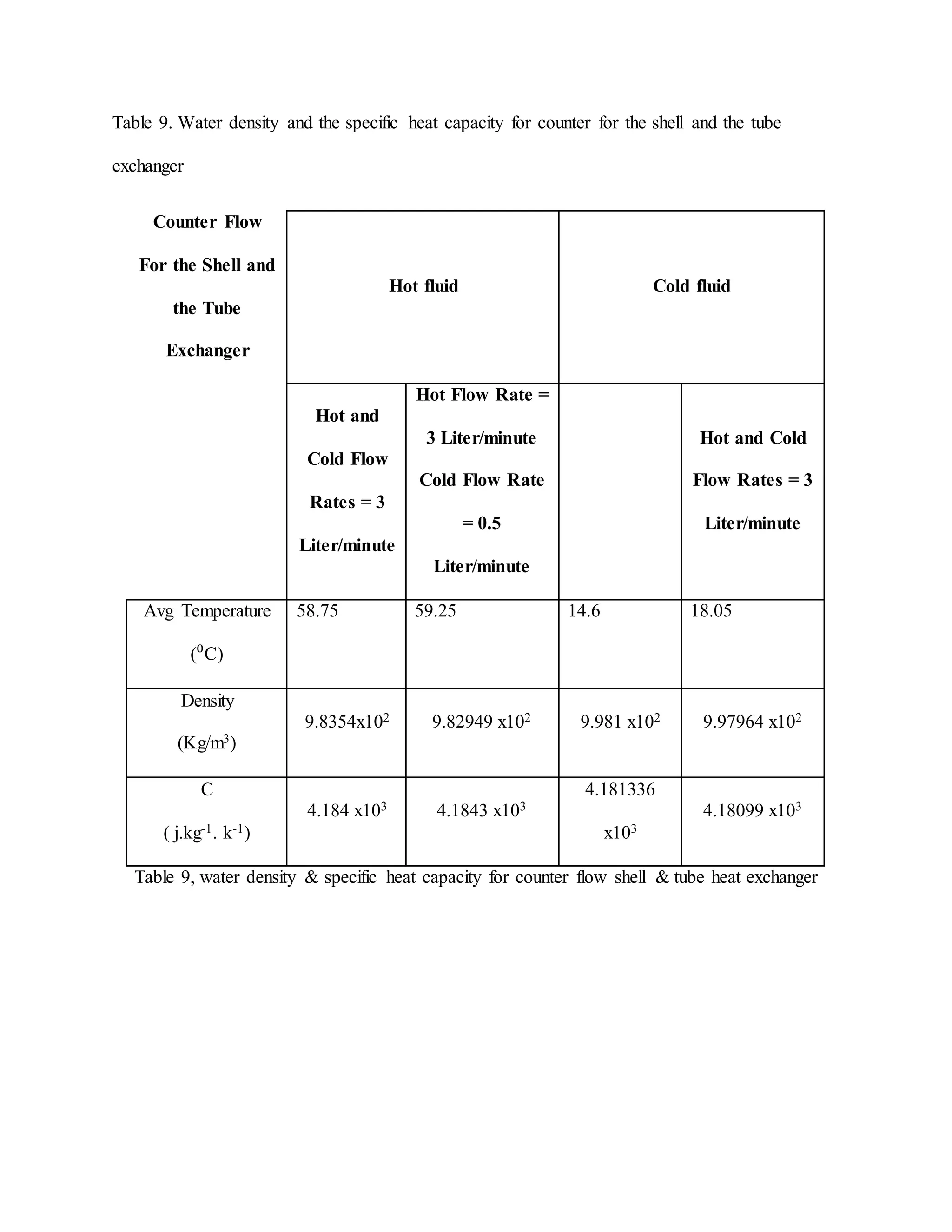
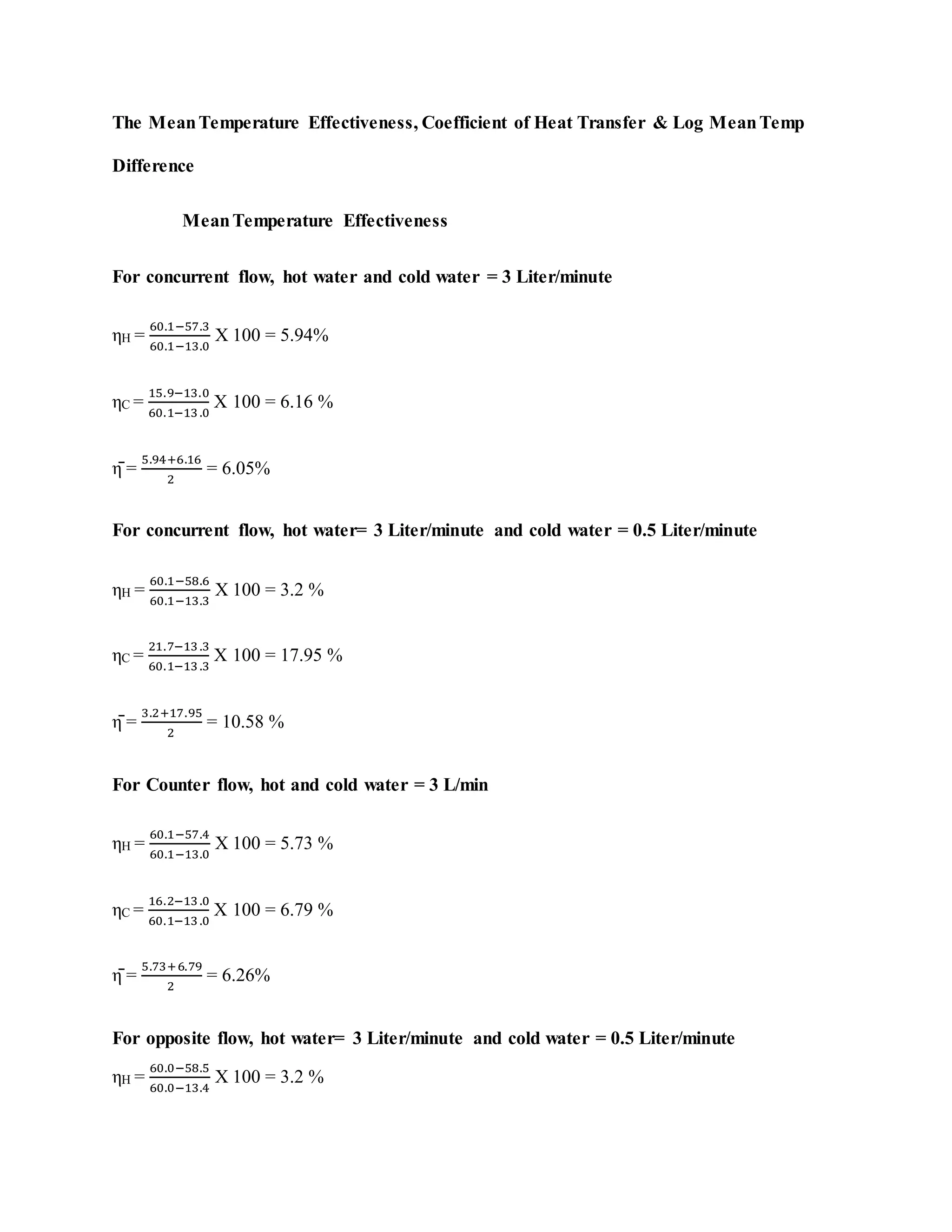
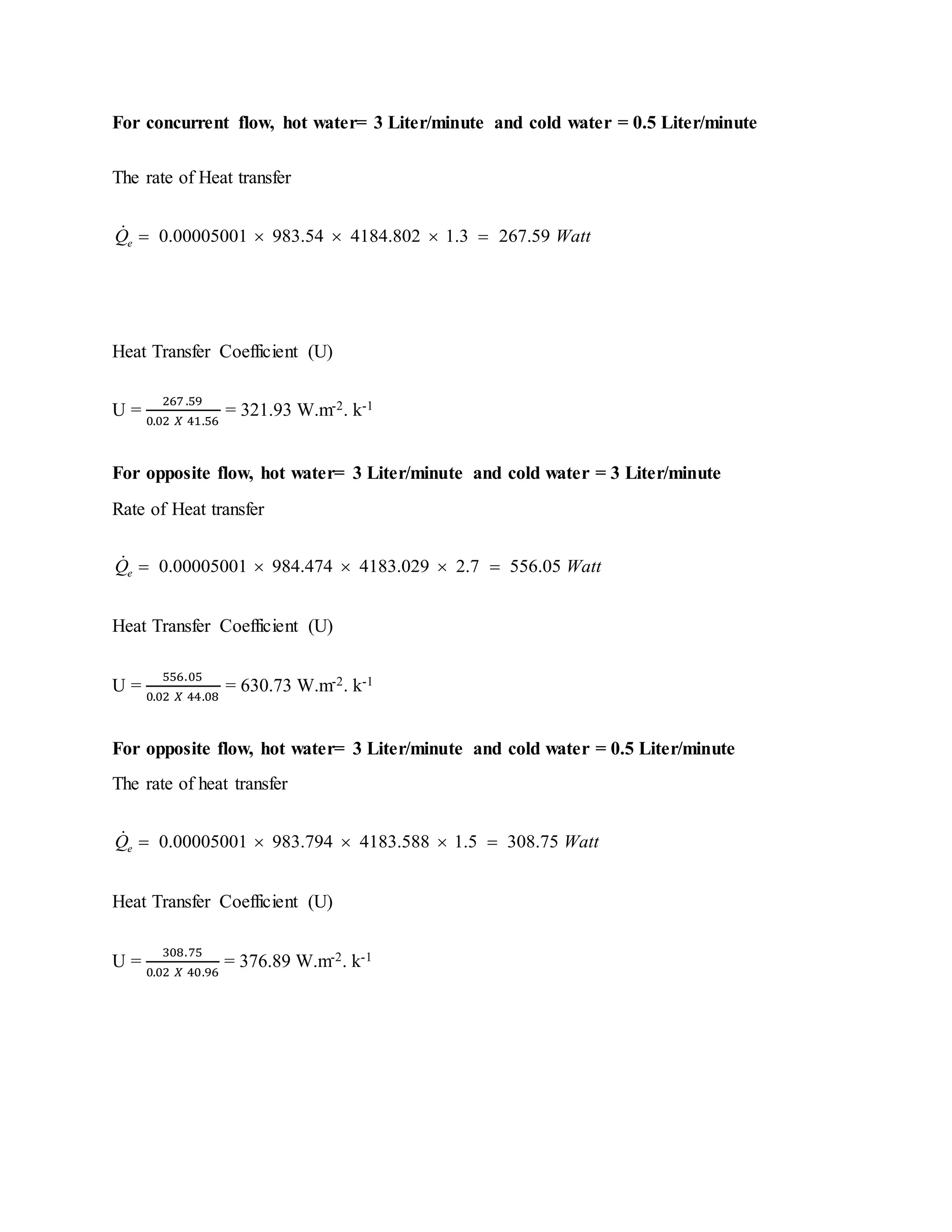
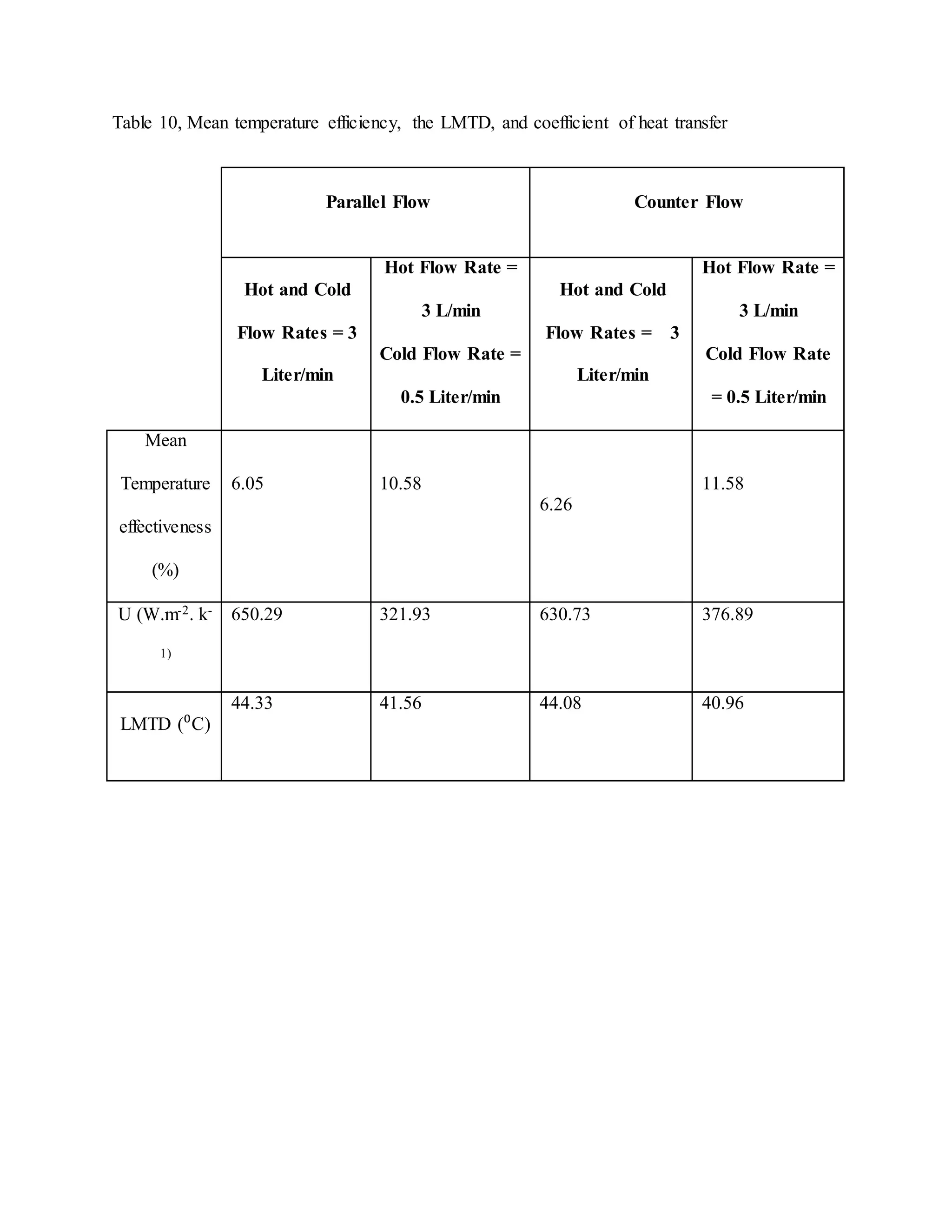
1.0.Introduction
The heat exchanger is a device in which as the name refers, exchange of heat occurs
between two fluids (gases or liquids) that come in and leave at varied temperature levels. The
core objective of the equipment in an industrial set-up is to achieve a suitable temperature of
a fluid by adding or removing heat from it. Inside the heat exchanger, there are three possible
fluid motion: parallel, counter and cross-flow. In parallel (co-current) flow, the two fluids;
both the cold and the hot fluids move flow at like direction – they get in and leave the
equipment on the like ends. In counter configuartion, the two fluids flow in counter
directions, that is, the fluids enter and leave the exchange at opposite ends. In this
experiment, two kinds of heat exchangers are employed that involve shell and tube as well as
plate heat exchanger.
Co-current flow occurs when the two fluids enter the exchanger at their extreme
temperature difference. Over the length of the exchanger, this temperature difference
becomes lesser and lesser. On the other hand, in the in the counter flow configuration, both
the two fluids enters the exchanger at opposite ends and at the same time different ends of the
temperature scale. As both fluids flow through this aperture, the become heated ad cooled at
almost an equal rate. Apparently, the differential of the temperature that is between the hot
fluid and the cold fluid is relatively fixed over the entire length of the device.
Figure 1. Parallel flow
Figure 2. Counter flow
The process of heat exchange that occurs in an ideal equipement equipment is
summarized as shown in the proceding equations.
( )
( )( )
h
c
h h ph
c c pc
T
Q m c T
Q m c T
F LMTD
Q F UA LMTD
R
 
 
 
Where F represents correction factor, LMTD represents Log Mean Temperature
Difference, and Q is heat quantity transferred between the cold fluid and the hot fluid.
Overall resistance of the process can be presented as:
T hf w cfR R R R  
1
2
1
2
1
ln
2
1
hf
h
w
w
cf
c
R
A h
D
D
R
Lk
R
A h


 
  

In the above equations, hc and hh can be determined using the correct Nusselt constant
for both the hot fluid and the cold fluid. For instance
For the hot fluid
0.8 0.3
0.023Re Pr
h
h h
h
h h h
K
h Nu
D
Nu
 
  

For the cold fluid
0.55 0.33
0.36Re Pr
c
c c
c
c c c
K
h Nu
D
Nu
 
  

The LMTD of the process can be presented by an equation where a and b represents
the device. LMTD is employed as the heat must pass through four resistance stages.
 
ln
a b
a
b
T T
Tm
T
T
  
 
 
  
The efficiency of the device is presented as the proportion of the existing rate of heat
transfer of a specific heat exchanger to the extreme rate of heat transfer of the unit.
 
max
max min ht ct
Q
Q
Q C T T
 
 
The objective of the experiment was to investigate the working of two heat
exchangers. In this lab report computation on the heat exchange as well as heat loss are
carried out to study the energy balance. The heat transfer coefficient and the LMTD are also
calculated for this type of experiment. In this experiment, it is realize that the counter flow
configuration of fluids in the shell and the tube heat exchanger has more efficiency compared
to the parallel flow configuration.
2.0.Materials and methods
2.1. Materials
In this experiment a plate heat exchanger as well as a shell and tube heat exchangers were
used. The shell and tube heat exchanger used was compact and could do the work at high
temperatures. The device has a large tube (shell) surround numerous smaller tubes known as
the bundle. One fluid circuit passes through this bundle while the other passes through the
shell.
Figure 3. The Shell and Tube Heat Exchanger
The plate heat exchanger is compact and also effective. This makes it excellent for
use with squeezed space. The devices involves a layer of plates that are separated by spacers
(gaskets). The spacers and plates have openings where the hot fluids and the cold fluids pass
alternatively through these plates. Although the arrangements are entirely separated, heat
exchanges through these metal plates.
Figure 4. Plate Heat Exchanger
2.2.Methods
2.2.1. shell and tube heat exchanger
A proper inspection was required to ensure that the setup was in the right working
state. These valves were inspected to be at first closed before this experiment. The hot fluid
reservoir was then filled up through a fluid pipe. After the tank was full, the valves were then
closed. Thereafter, the cold fluid tank was then filled up by letting the valve and a drain hose
was then linked to the cold fluid drain point. A water temperature controller was stationed at
a set point. The temperature of fluid in the hot fluid tank was regulated to attain this set point
temperature.
Counter-current
This configuration of this valve of the shell as well as the tube exchanger was
switched to counter-current before this experiment started. The valves were adjusted in order
to attain the required flow rates for both the cold and the hot fluid streams respectively. After
ten minutes, the equipment was enabled to reach a settled state, thereby, data was taken. The
steps were repeated for various combinations of flow rates.
Co-current
This configuration of this valve of the shell as well as the tube exchanger was
switched to co-current before this experiment started. The valves were adjusted in order to
attain the required flow rates for both the cold and the hot fluid streams respectively. After
ten minutes, the equipment was enabled to reach a settled state, thereby, data was taken. The
steps were repeated for various combinations of flow rates.
2.2.2. plate heat exchanger
Constant flow of fluids was allowed into the aperture and the temperature variation
between the cold and hot fluids measured. The pump was set at the maximum capacity flow
rate and the temperature variation between the outlet and inlet of the hot fluid measured.
3. Results
3.1 Plate Heat Exchanger
Room Temperature: 26 ⁰C
Heater Reservoir Temperature: 60.7 ⁰C
Table 1, Plate Heat Exchanger (concurrent)
#
Hot
Water
Flow Rate
(L/minute)
Cold
Water
Flow Rate
(L/minute)
TH1 TH2
Temp
diff
Avg
TH
TC1 TC2 ΔTC
Avg
TC
1 3 3 59.3 54.6 4.7 56.95 12.8 18.0 5.2 15.4
2 3 0.5 59.4 57.0 2.7 58.2 13.0 29.9 16.9 21.45
Table 2, Plate Heat Exchanger (counter flow).
#
Hot
Water
Flow Rate
(L/minute)
Cold
Water
Flow Rate
(L/minute)
TH1 TH2
Temp
diff
Avg
TH
TC1 TC2 ΔTC
Avg
TC
1 3 3 59.6 58.2 1.4 58.7 17.8 20.2 2.4 19.0
2 3 0.5 60.3 59.5 0.8 59.9 17.8 25.2 7.4 21.5
Where,
ΔTH = TH1 - TH2 Eqn (1)
ΔTC = TC2 – TC1 Eqn (2)
Avg TH
Eqn (3)
AvgTC
Eqn (4)
Plate Heat Exchanger
Charts and graphs
3.1.2A Charts of temperatures of test
(Parallel Flow)
Fig. 5, concurrent flow for 3 Liter/minute
Fig. 2, concurrent flow for 3 Liter/minute
Temp of test (Counter-configuration)
Fig. 4, counter flow for 0.5 Liter/minute
Fig. 3. counter flow for 3 Liter/minute
3.1.3 Converting flow rates from Liter/minute to cubic meters per second
1 Liter/minute = 0.00001667 m3/s
Thus,
3 Liter/minute = 0.00005001 m3/s
0.5 Liter/minute = 0.000008335 m3/s
Calculating the density of water
Fig 5. The water density chart
Using the equation
Eqn (5)
Calculating the specific heat capacity of water
Fig 6. Water Specific Heat Capacity
Also, water density can be calculated using the following equation.
Eqn (6)
Table 3. Water density and the specific heat capacity for concurrent flow plate heat
exchanger
Parallel Flow
For Exchanger
(Plate Heat
exchanger)
Hot fluid Cold fluid
Hot and
Cold Flow
Rates = 3
L/min
Hot Flow Rate =
3 L/min
Cold Flow Rate
= 0.5 L/min
Hot and
Cold Flow
Rates = 3
L/min
Hot Flow Rate
= 3 L/min
Cold Flow Rate
= 0.5 L/min
Avg Temperature
(⁰C)
58.9 53.8 12.7 18.1
Density
(Kg/m3)
9.8354x10² 9.82949 x10² 9.981 x10² 9.97964 x10²
C
( j.kg-1. k-1)
4.184 x10³ 4.1843 x10³
4.181336
x103
4.18099 x10³
Table 4, Water density and the specific heat capacity for concurrent flow plate heat
exchanger
Parallel Flow
For Exchanger
(Plate Heat
exchanger)
Hot fluid Cold fluid
Hot and
Cold Flow
Rates = 3
L/min
Hot Flow Rate =
3 L/min
Cold Flow Rate
= 0.5 L/min
Hot and
Cold Flow
Rates = 3
L/min
Hot Flow Rate
= 3 L/min
Cold Flow Rate
= 0.5 L/min
Avg Temperature
(⁰C)
59.9 57.2 13 29.9
Density
(Kg/m3)
9.8354x10² 9.82949 x10² 9.981 x10² 9.97964 x10²
C
( j.kg-1. k-1)
4.184 x10³ 4.1843 x10³
4.181336
x103
4.18099 x10³
The MeanTemperature Effectiveness, Coefficient of Heat Transfer & Log MeanTemp
Difference
MeanTemperature Effectiveness
Eqn (7)
Temperature efficiency of the hot circuit is given as:
Eqn (8)
Whereas the temperature efficiency of the cold circuit is given as:
Eqn (9)
For concurrent flow, hot water and cold water = 3 Liter/minute
ηH =
59.3−54.6
59.3−12.8
X 100 = 10.11 %
ηC =
18.0−12 .8
59.3−12.8
X 100 = 11.18 %
η̄ =
10.11+11.18
2
= 10.65%
For concurrent flow, hot water= 3 Liter/minute and cold water = 0.5 Liter/minute
ηH =
59.6−58.2
59.6−17.8
X 100 = 3.35%
ηC =
20.2−17 .8
59.6−17.8
X 100 = 5.74 %
η̄ =
3.35+5.74
2
= 4.55%
For opposite flow, hot water= 3 Liter/minute and cold water = 0.5 Liter/minute
ηH =
59.6−58.3
59.6−17.8
X 100 = 3.11 %
ηC =
20.2−17 .8
59.6−17.8
X 100 = 5.74 %
η̄ =
3.11+5.74
2
= 4.43 %
For Counter flow, hot = 3 L/min and cold water = 0.5 L/min
ηH =
60.3−59.5
60.3−17.8
X 100 = 1.88 %
ηC =
25.2−17 .8
60.3−17 .8
X 100 = 17.41 %
η̄ =
1.88+17.41
2
= 9.65 %
LMTD
Eqn (10)
Hot water= 3 Liter/minute and cold water = 0.5 Liter/minute LMTD =
(54.5−18.0)−(59.3−12.8)
ln⁡(
(54.5−18 .0)
(59.3−12 .8)
)
= 41.30 ⁰C
For concurrent flow, hot water= 3 Liter/minute and cold water = 0.5 Liter/minute
LMTD =
(59.3−20.2)−(59.6−17.8)
ln ⁡(
(59.3−20.2)
(59.6−17.8)
)
= 40.43 ⁰C
For opposite flow, hot water= 3 Liter/minute and cold water = 0.5 Liter/minute
LMTD =
(59.6−20.2)−(59.6−17.8)
ln ⁡(
(59.6−20.2)
(59.6−17.8)
)
= 40.59 ⁰C
For Counter flow, hot = 3 L/min and cold water = 0.5 L/min
LMTD =
(59.5−25.2)−(60.3−17.8)
ln⁡(
(59.5−25.2)
(60.3−17.8)
)
= 38.25 ⁰C
Coefficient of the Heat Transfer (U)
Eqn (11)
Where,
e H pQ m X c H X ΔT Eqn (12)
Q҅ e = 0.00005001 983.540 4183.631 4.7 967.171 Watt   
Heat Transfer Coefficient (U)
U =
967.171
0.02 ⁡𝑋⁡41.30⁡
= 1170.91 W.m-2. k-1
For concurrent flow, hot water= 3 Liter/minute and cold water = 0.5 Liter/minute
The rate of Heat transfer
0.00005001 982.949 4184.3 4.7 966.72eQ Watt    
U =
966.72
0.02 ⁡𝑋⁡40.43
= 1206.59 W.m-2. k-1
For opposite flow, hot water= 3 Liter/minute and cold water
The rate of Heat transfer
0.00005001 983.744 4183.631 1.4 287.96eQ X X X Watt 
U =
287.96
0.02 ⁡𝑋⁡40.59
= 354.72 W.m-2. k-1
For opposite flow, hot water= 3 Liter/minute and cold water = 0.5 Liter/minute
The rate of Heat transfer
0.00005001 983.181 4184.108 0.8 164.58eQ X X X Watt 
U =
164.58
0.02 ⁡𝑋⁡38.25
= 215.10 W.m-2. k-1
Table 5. Mean temperature efficiency, the LMTD, and coefficient of heat transfer
Parallel Flow Counter Flow
Hot and
Cold Flow
Rates = 3
L/min
Hot Flow Rate =
3 L/min
Cold Flow Rate
= 0.5 L/min
Hot and
Cold Flow
Rates = 3
L/min
Hot Flow Rate
= 3 L/min
Cold Flow Rate
= 0.5 L/min
Mean Temperature
effectiveness (%)
10.65 4.55 4.43 9.65
U (W.m-2. k-1)
1170.91 1206.59 354.72
215.10
LMTD (⁰C) 41.30 40.43 40.59 38.25
The Shell and the Tube Heat Exchanger
Room Temperature: 26.0 ⁰C
The Heater Reservoir Temperature: 60.2 ⁰C
Table of temperatures of test (concurrent Flow)
Table 6. Shell and the Tube Heat Exchanger (concurrent flow).
#
Hot
Water
Flow Rate
(L/minute)
Cold
Water
Flow Rate
(L/minute)
TH1 TH2
Temp
diff
Avg
TH
TC1 TC2 ΔTC
Avg
TC
1 3 3 60.1 57.3 2.8 58.7 13.0 15.9 2.9 14.45
2 3 0.5 59.9 58.6 1.3 59.25 13.3 21.7 8.4 17.5
3.2.1B Temperatures of test (Opposite Flow)
Table 7, Shell and Tube Heat Exchanger (counter flow).
#
Hot
Water
Flow Rate
(L/minute)
Cold
Water
Flow Rate
(L/minute)
TH1 TH2
Temp
diff
Avg
TH
TC1 TC2 ΔTC
Avg
TC
1 3 3 60.1 57.4 2.7 58.75 13.0 16.2 3.2 14.6
2 3 0.5 60.0 58.5 1.5 59.25 13.4 22.7 9.3 18.05
Where,
ΔTH = TH1 - TH2 Eqn (1)
ΔTC = TC2 – TC1 Eqn (2)
Avg TH
Eqn (3)
Average TC
Eqn (4)
3.2.2 Charts and Graphs for Plate Heat Exchanger
(Parallel Flow)
Figure 7, parallel flow for 3 L/min
Figure 8, Parallel flow for 0.5 L/min
3.1.2B Charts of temperature of test
(Counter-Flow)
Figure 9, counter flow for 3 L/min
Figure 10, counter flow for 0.5 L/min
3.2.4 Water density and the specific heat capacity for concurrent for the shell and the tube
exchanger
Table. 8. Water density and the specific heat capacity for concurrent for the shell and the tube
exchanger
Parallel Flow
For the Shell and
the Tube
Exchanger
Hot fluid Cold fluid
Hot and
Cold Flow
Rates = 3
Liter/minute
Hot Flow Rate =
3 Liter/minute
Cold Flow Rate
= 0.5
Liter/minute
Hot and
Cold Flow
Rates = 3
Liter/minute
Hot Flow Rate
=3Liter/minute
Cold Flow Rate
= 0.5
Liter/minute
Avg Temp (⁰C)
58.79 59.25 14.45 17.5
Density
(Kg/m3)
9.8354x10² 9.82949 x10² 9.981 x10² 9.97964 x10²
C
( j.kg-1. k-1)
4.184 x10³ 4.1843 x10³
4.181336
x103
4.18099 x10³
Table 9. Water density and the specific heat capacity for counter for the shell and the tube
exchanger
Counter Flow
For the Shell and
the Tube
Exchanger
Hot fluid Cold fluid
Hot and
Cold Flow
Rates = 3
Liter/minute
Hot Flow Rate =
3 Liter/minute
Cold Flow Rate
= 0.5
Liter/minute
Hot and Cold
Flow Rates = 3
Liter/minute
Avg Temperature
(⁰C)
58.75 59.25 14.6 18.05
Density
(Kg/m3)
9.8354x10² 9.82949 x10² 9.981 x10² 9.97964 x10²
C
( j.kg-1. k-1)
4.184 x10³ 4.1843 x10³
4.181336
x103
4.18099 x10³
Table 9, water density & specific heat capacity for counter flow shell & tube heat exchanger
The MeanTemperature Effectiveness, Coefficient of Heat Transfer & Log MeanTemp
Difference
MeanTemperature Effectiveness
For concurrent flow, hot water and cold water = 3 Liter/minute
ηH =
60.1−57.3
60.1−13.0
X 100 = 5.94%
ηC =
15.9−13.0
60.1−13.0
X 100 = 6.16 %
η̄ =
5.94+6.16
2
= 6.05%
For concurrent flow, hot water= 3 Liter/minute and cold water = 0.5 Liter/minute
ηH =
60.1−58.6
60.1−13.3
X 100 = 3.2 %
ηC =
21.7−13.3
60.1−13.3
X 100 = 17.95 %
η̄ =
3.2+17.95
2
= 10.58 %
For Counter flow, hot and cold water = 3 L/min
ηH =
60.1−57.4
60.1−13.0
X 100 = 5.73 %
ηC =
16.2−13.0
60.1−13.0
X 100 = 6.79 %
η̄ =
5.73+6.79
2
= 6.26%
For opposite flow, hot water= 3 Liter/minute and cold water = 0.5 Liter/minute
ηH =
60.0−58.5
60.0−13.4
X 100 = 3.2 %
ηC =
22.7−13.4
60.0−13.4
X 100 = 19.96%
η̄ =
3.2+19.96
2
= 11.58%
LMTD
Eqn (10)
For concurrent flow, hot water and cold water = 3 Liter/minute
(57.3−15.9)−(60.1−13.0)
ln⁡(
(57.3−15 .9)
(60.1−13 .0)
)
= 44.33 ⁰C
For concurrent flow, hot water= 3 Liter/minute and cold water = 0.5 Liter/minute
(58.6−21.7)−(59.9−13.3)
ln⁡(
(58.6−21.7)
(59.9−13.3)
)
= 41.56 ⁰C
For opposite flow, hot water= 3 Liter/minute and cold water = 3 Liter/minute
(57.4−16.2)−(60.1−13.0)
ln⁡(
(57.4−16.2)
(60.1−13.0)
)
= 44.08 ⁰C
For opposite flow, hot water= 3 Liter/minute and cold water = 0.5 Liter/minute
(58.5−22.7)−(60.0−13.4)
ln⁡(
(58.5−22.7)
(60.0−13.4)
)
= 40.96 ⁰C
Coefficient of Heat Transfer (U)
Eqn (11)
Where
e H pQ m X c H X HΔT Eqn (12)
A = 0.02 m2 for all heat exchangers
For concurrent flow, hot fluid and cold fluid = 3 Liter/minute
Rate of Heat transfer
e H pQ m X c H X HΔT
0.00005001 984.273 4183.192 2.8 576.55eQ Watt    
Heat Transfer Coefficient (U)
U =
576.55
0.02⁡𝑋⁡44.33
= 650.29 W.m-2. k-1
For concurrent flow, hot water= 3 Liter/minute and cold water = 0.5 Liter/minute
The rate of Heat transfer
0.00005001 983.54 4184.802 1.3 267.59eQ Watt    
Heat Transfer Coefficient (U)
U =
267 .59
0.02⁡𝑋⁡41.56
= 321.93 W.m-2. k-1
For opposite flow, hot water= 3 Liter/minute and cold water = 3 Liter/minute
Rate of Heat transfer
0.00005001 984.474 4183.029 2.7 556.05eQ Watt    
Heat Transfer Coefficient (U)
U =
556.05
0.02⁡𝑋⁡44.08
= 630.73 W.m-2. k-1
For opposite flow, hot water= 3 Liter/minute and cold water = 0.5 Liter/minute
The rate of heat transfer
0.00005001 983.794 4183.588 1.5 308.75eQ Watt    
Heat Transfer Coefficient (U)
U =
308.75
0.02⁡𝑋⁡40.96
= 376.89 W.m-2. k-1
Table 10, Mean temperature efficiency, the LMTD, and coefficient of heat transfer
Parallel Flow Counter Flow
Hot and Cold
Flow Rates = 3
Liter/min
Hot Flow Rate =
3 L/min
Cold Flow Rate =
0.5 Liter/min
Hot and Cold
Flow Rates = 3
Liter/min
Hot Flow Rate =
3 L/min
Cold Flow Rate
= 0.5 Liter/min
Mean
Temperature
effectiveness
(%)
6.05 10.58
6.26
11.58
U (W.m-2. k-
1)
650.29 321.93 630.73 376.89
LMTD (⁰C)
44.33 41.56 44.08 40.96
Discussion
From these data, the general features of a concurrent configuration and counter
configuration heat exchangers are noticeable. The results of this lab experiment reveal that the
effectiveness of the exchanger device is associated with flow rate of the cold fluid. This can be
seen by the decrease of the thermal resistance when the cold fluid is introduced to the flow. In
both the plate exchanger and tube and shell exchanger, the data collected for heat exchange did
not vary greatly. Also, there was no observable advantage of using eth parallel flow versus
counter current in the data.
Conclusion
The data that was presented in this report revealed that the working of this heat exchanger
increased linearly with the increase flow rate of the cold fluid. Therefore, this is observed
following logically as additional cold fluid is turned in to take away the heat. Also, the improved
rate of flow results in a rather disruptive flow, thereby improving the rate of heat transfer. In
reverse to the theory of heat exchangers, nevertheless, there’s no observable variation of the heat
exchange between the concurrent flow and the opposite flow. In this case, the opposite current
flow must have shown an improved ability of heat transfer.
References
Kakaç, S., & Ishii, M. (1983). Advances in Two-Phase Flow and Heat Transfer: Fundamentals
and Applications Volume II. Dordrecht: Springer Netherlands.
Kirklin, P. W. (1992). Aviation fuel: Thermal stability requirements ; [papers presented at the
symposium held in Toronto, Ontario, Canada on 26 June 1991]. Philadelphia, Pa.

Heat exchanger lab 2

  • 1.
    1.0.Introduction The heat exchangeris a device in which as the name refers, exchange of heat occurs between two fluids (gases or liquids) that come in and leave at varied temperature levels. The core objective of the equipment in an industrial set-up is to achieve a suitable temperature of a fluid by adding or removing heat from it. Inside the heat exchanger, there are three possible fluid motion: parallel, counter and cross-flow. In parallel (co-current) flow, the two fluids; both the cold and the hot fluids move flow at like direction – they get in and leave the equipment on the like ends. In counter configuartion, the two fluids flow in counter directions, that is, the fluids enter and leave the exchange at opposite ends. In this experiment, two kinds of heat exchangers are employed that involve shell and tube as well as plate heat exchanger. Co-current flow occurs when the two fluids enter the exchanger at their extreme temperature difference. Over the length of the exchanger, this temperature difference becomes lesser and lesser. On the other hand, in the in the counter flow configuration, both the two fluids enters the exchanger at opposite ends and at the same time different ends of the temperature scale. As both fluids flow through this aperture, the become heated ad cooled at almost an equal rate. Apparently, the differential of the temperature that is between the hot fluid and the cold fluid is relatively fixed over the entire length of the device.
  • 2.
    Figure 1. Parallelflow Figure 2. Counter flow The process of heat exchange that occurs in an ideal equipement equipment is summarized as shown in the proceding equations. ( ) ( )( ) h c h h ph c c pc T Q m c T Q m c T F LMTD Q F UA LMTD R       Where F represents correction factor, LMTD represents Log Mean Temperature Difference, and Q is heat quantity transferred between the cold fluid and the hot fluid. Overall resistance of the process can be presented as: T hf w cfR R R R   1 2 1 2 1 ln 2 1 hf h w w cf c R A h D D R Lk R A h        
  • 3.
    In the aboveequations, hc and hh can be determined using the correct Nusselt constant for both the hot fluid and the cold fluid. For instance For the hot fluid 0.8 0.3 0.023Re Pr h h h h h h h K h Nu D Nu       For the cold fluid 0.55 0.33 0.36Re Pr c c c c c c c K h Nu D Nu       The LMTD of the process can be presented by an equation where a and b represents the device. LMTD is employed as the heat must pass through four resistance stages.   ln a b a b T T Tm T T           The efficiency of the device is presented as the proportion of the existing rate of heat transfer of a specific heat exchanger to the extreme rate of heat transfer of the unit.   max max min ht ct Q Q Q C T T     The objective of the experiment was to investigate the working of two heat exchangers. In this lab report computation on the heat exchange as well as heat loss are carried out to study the energy balance. The heat transfer coefficient and the LMTD are also calculated for this type of experiment. In this experiment, it is realize that the counter flow
  • 4.
    configuration of fluidsin the shell and the tube heat exchanger has more efficiency compared to the parallel flow configuration. 2.0.Materials and methods 2.1. Materials In this experiment a plate heat exchanger as well as a shell and tube heat exchangers were used. The shell and tube heat exchanger used was compact and could do the work at high temperatures. The device has a large tube (shell) surround numerous smaller tubes known as the bundle. One fluid circuit passes through this bundle while the other passes through the shell.
  • 5.
    Figure 3. TheShell and Tube Heat Exchanger The plate heat exchanger is compact and also effective. This makes it excellent for use with squeezed space. The devices involves a layer of plates that are separated by spacers (gaskets). The spacers and plates have openings where the hot fluids and the cold fluids pass alternatively through these plates. Although the arrangements are entirely separated, heat exchanges through these metal plates.
  • 6.
    Figure 4. PlateHeat Exchanger 2.2.Methods 2.2.1. shell and tube heat exchanger A proper inspection was required to ensure that the setup was in the right working state. These valves were inspected to be at first closed before this experiment. The hot fluid reservoir was then filled up through a fluid pipe. After the tank was full, the valves were then
  • 7.
    closed. Thereafter, thecold fluid tank was then filled up by letting the valve and a drain hose was then linked to the cold fluid drain point. A water temperature controller was stationed at a set point. The temperature of fluid in the hot fluid tank was regulated to attain this set point temperature. Counter-current This configuration of this valve of the shell as well as the tube exchanger was switched to counter-current before this experiment started. The valves were adjusted in order to attain the required flow rates for both the cold and the hot fluid streams respectively. After ten minutes, the equipment was enabled to reach a settled state, thereby, data was taken. The steps were repeated for various combinations of flow rates. Co-current This configuration of this valve of the shell as well as the tube exchanger was switched to co-current before this experiment started. The valves were adjusted in order to attain the required flow rates for both the cold and the hot fluid streams respectively. After ten minutes, the equipment was enabled to reach a settled state, thereby, data was taken. The steps were repeated for various combinations of flow rates. 2.2.2. plate heat exchanger Constant flow of fluids was allowed into the aperture and the temperature variation between the cold and hot fluids measured. The pump was set at the maximum capacity flow rate and the temperature variation between the outlet and inlet of the hot fluid measured.
  • 8.
    3. Results 3.1 PlateHeat Exchanger Room Temperature: 26 ⁰C Heater Reservoir Temperature: 60.7 ⁰C Table 1, Plate Heat Exchanger (concurrent) # Hot Water Flow Rate (L/minute) Cold Water Flow Rate (L/minute) TH1 TH2 Temp diff Avg TH TC1 TC2 ΔTC Avg TC 1 3 3 59.3 54.6 4.7 56.95 12.8 18.0 5.2 15.4 2 3 0.5 59.4 57.0 2.7 58.2 13.0 29.9 16.9 21.45 Table 2, Plate Heat Exchanger (counter flow). # Hot Water Flow Rate (L/minute) Cold Water Flow Rate (L/minute) TH1 TH2 Temp diff Avg TH TC1 TC2 ΔTC Avg TC 1 3 3 59.6 58.2 1.4 58.7 17.8 20.2 2.4 19.0 2 3 0.5 60.3 59.5 0.8 59.9 17.8 25.2 7.4 21.5
  • 9.
    Where, ΔTH = TH1- TH2 Eqn (1) ΔTC = TC2 – TC1 Eqn (2) Avg TH Eqn (3) AvgTC Eqn (4) Plate Heat Exchanger Charts and graphs 3.1.2A Charts of temperatures of test (Parallel Flow) Fig. 5, concurrent flow for 3 Liter/minute Fig. 2, concurrent flow for 3 Liter/minute
  • 10.
    Temp of test(Counter-configuration) Fig. 4, counter flow for 0.5 Liter/minute Fig. 3. counter flow for 3 Liter/minute 3.1.3 Converting flow rates from Liter/minute to cubic meters per second 1 Liter/minute = 0.00001667 m3/s Thus, 3 Liter/minute = 0.00005001 m3/s 0.5 Liter/minute = 0.000008335 m3/s Calculating the density of water
  • 11.
    Fig 5. Thewater density chart Using the equation Eqn (5) Calculating the specific heat capacity of water Fig 6. Water Specific Heat Capacity
  • 12.
    Also, water densitycan be calculated using the following equation. Eqn (6) Table 3. Water density and the specific heat capacity for concurrent flow plate heat exchanger Parallel Flow For Exchanger (Plate Heat exchanger) Hot fluid Cold fluid Hot and Cold Flow Rates = 3 L/min Hot Flow Rate = 3 L/min Cold Flow Rate = 0.5 L/min Hot and Cold Flow Rates = 3 L/min Hot Flow Rate = 3 L/min Cold Flow Rate = 0.5 L/min Avg Temperature (⁰C) 58.9 53.8 12.7 18.1 Density (Kg/m3) 9.8354x10² 9.82949 x10² 9.981 x10² 9.97964 x10² C ( j.kg-1. k-1) 4.184 x10³ 4.1843 x10³ 4.181336 x10³ 4.18099 x10³
  • 13.
    Table 4, Waterdensity and the specific heat capacity for concurrent flow plate heat exchanger Parallel Flow For Exchanger (Plate Heat exchanger) Hot fluid Cold fluid Hot and Cold Flow Rates = 3 L/min Hot Flow Rate = 3 L/min Cold Flow Rate = 0.5 L/min Hot and Cold Flow Rates = 3 L/min Hot Flow Rate = 3 L/min Cold Flow Rate = 0.5 L/min Avg Temperature (⁰C) 59.9 57.2 13 29.9 Density (Kg/m3) 9.8354x10² 9.82949 x10² 9.981 x10² 9.97964 x10² C ( j.kg-1. k-1) 4.184 x10³ 4.1843 x10³ 4.181336 x10³ 4.18099 x10³ The MeanTemperature Effectiveness, Coefficient of Heat Transfer & Log MeanTemp Difference MeanTemperature Effectiveness Eqn (7)
  • 14.
    Temperature efficiency ofthe hot circuit is given as: Eqn (8) Whereas the temperature efficiency of the cold circuit is given as: Eqn (9) For concurrent flow, hot water and cold water = 3 Liter/minute ηH = 59.3−54.6 59.3−12.8 X 100 = 10.11 % ηC = 18.0−12 .8 59.3−12.8 X 100 = 11.18 % η̄ = 10.11+11.18 2 = 10.65% For concurrent flow, hot water= 3 Liter/minute and cold water = 0.5 Liter/minute ηH = 59.6−58.2 59.6−17.8 X 100 = 3.35% ηC = 20.2−17 .8 59.6−17.8 X 100 = 5.74 % η̄ = 3.35+5.74 2 = 4.55% For opposite flow, hot water= 3 Liter/minute and cold water = 0.5 Liter/minute ηH = 59.6−58.3 59.6−17.8 X 100 = 3.11 %
  • 15.
    ηC = 20.2−17 .8 59.6−17.8 X100 = 5.74 % η̄ = 3.11+5.74 2 = 4.43 % For Counter flow, hot = 3 L/min and cold water = 0.5 L/min ηH = 60.3−59.5 60.3−17.8 X 100 = 1.88 % ηC = 25.2−17 .8 60.3−17 .8 X 100 = 17.41 % η̄ = 1.88+17.41 2 = 9.65 % LMTD Eqn (10) Hot water= 3 Liter/minute and cold water = 0.5 Liter/minute LMTD = (54.5−18.0)−(59.3−12.8) ln⁡( (54.5−18 .0) (59.3−12 .8) ) = 41.30 ⁰C For concurrent flow, hot water= 3 Liter/minute and cold water = 0.5 Liter/minute LMTD = (59.3−20.2)−(59.6−17.8) ln ⁡( (59.3−20.2) (59.6−17.8) ) = 40.43 ⁰C For opposite flow, hot water= 3 Liter/minute and cold water = 0.5 Liter/minute
  • 16.
    LMTD = (59.6−20.2)−(59.6−17.8) ln ⁡( (59.6−20.2) (59.6−17.8) ) =40.59 ⁰C For Counter flow, hot = 3 L/min and cold water = 0.5 L/min LMTD = (59.5−25.2)−(60.3−17.8) ln⁡( (59.5−25.2) (60.3−17.8) ) = 38.25 ⁰C Coefficient of the Heat Transfer (U) Eqn (11) Where, e H pQ m X c H X ΔT Eqn (12) Q҅ e = 0.00005001 983.540 4183.631 4.7 967.171 Watt    Heat Transfer Coefficient (U) U = 967.171 0.02 ⁡𝑋⁡41.30⁡ = 1170.91 W.m-2. k-1 For concurrent flow, hot water= 3 Liter/minute and cold water = 0.5 Liter/minute The rate of Heat transfer
  • 17.
    0.00005001 982.949 4184.34.7 966.72eQ Watt     U = 966.72 0.02 ⁡𝑋⁡40.43 = 1206.59 W.m-2. k-1 For opposite flow, hot water= 3 Liter/minute and cold water The rate of Heat transfer 0.00005001 983.744 4183.631 1.4 287.96eQ X X X Watt  U = 287.96 0.02 ⁡𝑋⁡40.59 = 354.72 W.m-2. k-1 For opposite flow, hot water= 3 Liter/minute and cold water = 0.5 Liter/minute The rate of Heat transfer 0.00005001 983.181 4184.108 0.8 164.58eQ X X X Watt  U = 164.58 0.02 ⁡𝑋⁡38.25 = 215.10 W.m-2. k-1
  • 18.
    Table 5. Meantemperature efficiency, the LMTD, and coefficient of heat transfer Parallel Flow Counter Flow Hot and Cold Flow Rates = 3 L/min Hot Flow Rate = 3 L/min Cold Flow Rate = 0.5 L/min Hot and Cold Flow Rates = 3 L/min Hot Flow Rate = 3 L/min Cold Flow Rate = 0.5 L/min Mean Temperature effectiveness (%) 10.65 4.55 4.43 9.65 U (W.m-2. k-1) 1170.91 1206.59 354.72 215.10 LMTD (⁰C) 41.30 40.43 40.59 38.25
  • 19.
    The Shell andthe Tube Heat Exchanger Room Temperature: 26.0 ⁰C The Heater Reservoir Temperature: 60.2 ⁰C Table of temperatures of test (concurrent Flow) Table 6. Shell and the Tube Heat Exchanger (concurrent flow). # Hot Water Flow Rate (L/minute) Cold Water Flow Rate (L/minute) TH1 TH2 Temp diff Avg TH TC1 TC2 ΔTC Avg TC 1 3 3 60.1 57.3 2.8 58.7 13.0 15.9 2.9 14.45 2 3 0.5 59.9 58.6 1.3 59.25 13.3 21.7 8.4 17.5 3.2.1B Temperatures of test (Opposite Flow) Table 7, Shell and Tube Heat Exchanger (counter flow). # Hot Water Flow Rate (L/minute) Cold Water Flow Rate (L/minute) TH1 TH2 Temp diff Avg TH TC1 TC2 ΔTC Avg TC 1 3 3 60.1 57.4 2.7 58.75 13.0 16.2 3.2 14.6 2 3 0.5 60.0 58.5 1.5 59.25 13.4 22.7 9.3 18.05
  • 20.
    Where, ΔTH = TH1- TH2 Eqn (1) ΔTC = TC2 – TC1 Eqn (2) Avg TH Eqn (3) Average TC Eqn (4) 3.2.2 Charts and Graphs for Plate Heat Exchanger (Parallel Flow) Figure 7, parallel flow for 3 L/min Figure 8, Parallel flow for 0.5 L/min
  • 21.
    3.1.2B Charts oftemperature of test (Counter-Flow) Figure 9, counter flow for 3 L/min Figure 10, counter flow for 0.5 L/min
  • 22.
    3.2.4 Water densityand the specific heat capacity for concurrent for the shell and the tube exchanger Table. 8. Water density and the specific heat capacity for concurrent for the shell and the tube exchanger Parallel Flow For the Shell and the Tube Exchanger Hot fluid Cold fluid Hot and Cold Flow Rates = 3 Liter/minute Hot Flow Rate = 3 Liter/minute Cold Flow Rate = 0.5 Liter/minute Hot and Cold Flow Rates = 3 Liter/minute Hot Flow Rate =3Liter/minute Cold Flow Rate = 0.5 Liter/minute Avg Temp (⁰C) 58.79 59.25 14.45 17.5 Density (Kg/m3) 9.8354x10² 9.82949 x10² 9.981 x10² 9.97964 x10² C ( j.kg-1. k-1) 4.184 x10³ 4.1843 x10³ 4.181336 x10³ 4.18099 x10³
  • 23.
    Table 9. Waterdensity and the specific heat capacity for counter for the shell and the tube exchanger Counter Flow For the Shell and the Tube Exchanger Hot fluid Cold fluid Hot and Cold Flow Rates = 3 Liter/minute Hot Flow Rate = 3 Liter/minute Cold Flow Rate = 0.5 Liter/minute Hot and Cold Flow Rates = 3 Liter/minute Avg Temperature (⁰C) 58.75 59.25 14.6 18.05 Density (Kg/m3) 9.8354x10² 9.82949 x10² 9.981 x10² 9.97964 x10² C ( j.kg-1. k-1) 4.184 x10³ 4.1843 x10³ 4.181336 x10³ 4.18099 x10³ Table 9, water density & specific heat capacity for counter flow shell & tube heat exchanger
  • 24.
    The MeanTemperature Effectiveness,Coefficient of Heat Transfer & Log MeanTemp Difference MeanTemperature Effectiveness For concurrent flow, hot water and cold water = 3 Liter/minute ηH = 60.1−57.3 60.1−13.0 X 100 = 5.94% ηC = 15.9−13.0 60.1−13.0 X 100 = 6.16 % η̄ = 5.94+6.16 2 = 6.05% For concurrent flow, hot water= 3 Liter/minute and cold water = 0.5 Liter/minute ηH = 60.1−58.6 60.1−13.3 X 100 = 3.2 % ηC = 21.7−13.3 60.1−13.3 X 100 = 17.95 % η̄ = 3.2+17.95 2 = 10.58 % For Counter flow, hot and cold water = 3 L/min ηH = 60.1−57.4 60.1−13.0 X 100 = 5.73 % ηC = 16.2−13.0 60.1−13.0 X 100 = 6.79 % η̄ = 5.73+6.79 2 = 6.26% For opposite flow, hot water= 3 Liter/minute and cold water = 0.5 Liter/minute ηH = 60.0−58.5 60.0−13.4 X 100 = 3.2 %
  • 25.
    ηC = 22.7−13.4 60.0−13.4 X 100= 19.96% η̄ = 3.2+19.96 2 = 11.58% LMTD Eqn (10) For concurrent flow, hot water and cold water = 3 Liter/minute (57.3−15.9)−(60.1−13.0) ln⁡( (57.3−15 .9) (60.1−13 .0) ) = 44.33 ⁰C For concurrent flow, hot water= 3 Liter/minute and cold water = 0.5 Liter/minute (58.6−21.7)−(59.9−13.3) ln⁡( (58.6−21.7) (59.9−13.3) ) = 41.56 ⁰C For opposite flow, hot water= 3 Liter/minute and cold water = 3 Liter/minute (57.4−16.2)−(60.1−13.0) ln⁡( (57.4−16.2) (60.1−13.0) ) = 44.08 ⁰C For opposite flow, hot water= 3 Liter/minute and cold water = 0.5 Liter/minute
  • 26.
    (58.5−22.7)−(60.0−13.4) ln⁡( (58.5−22.7) (60.0−13.4) ) = 40.96 ⁰C Coefficientof Heat Transfer (U) Eqn (11) Where e H pQ m X c H X HΔT Eqn (12) A = 0.02 m2 for all heat exchangers For concurrent flow, hot fluid and cold fluid = 3 Liter/minute Rate of Heat transfer e H pQ m X c H X HΔT 0.00005001 984.273 4183.192 2.8 576.55eQ Watt     Heat Transfer Coefficient (U) U = 576.55 0.02⁡𝑋⁡44.33 = 650.29 W.m-2. k-1
  • 27.
    For concurrent flow,hot water= 3 Liter/minute and cold water = 0.5 Liter/minute The rate of Heat transfer 0.00005001 983.54 4184.802 1.3 267.59eQ Watt     Heat Transfer Coefficient (U) U = 267 .59 0.02⁡𝑋⁡41.56 = 321.93 W.m-2. k-1 For opposite flow, hot water= 3 Liter/minute and cold water = 3 Liter/minute Rate of Heat transfer 0.00005001 984.474 4183.029 2.7 556.05eQ Watt     Heat Transfer Coefficient (U) U = 556.05 0.02⁡𝑋⁡44.08 = 630.73 W.m-2. k-1 For opposite flow, hot water= 3 Liter/minute and cold water = 0.5 Liter/minute The rate of heat transfer 0.00005001 983.794 4183.588 1.5 308.75eQ Watt     Heat Transfer Coefficient (U) U = 308.75 0.02⁡𝑋⁡40.96 = 376.89 W.m-2. k-1
  • 28.
    Table 10, Meantemperature efficiency, the LMTD, and coefficient of heat transfer Parallel Flow Counter Flow Hot and Cold Flow Rates = 3 Liter/min Hot Flow Rate = 3 L/min Cold Flow Rate = 0.5 Liter/min Hot and Cold Flow Rates = 3 Liter/min Hot Flow Rate = 3 L/min Cold Flow Rate = 0.5 Liter/min Mean Temperature effectiveness (%) 6.05 10.58 6.26 11.58 U (W.m-2. k- 1) 650.29 321.93 630.73 376.89 LMTD (⁰C) 44.33 41.56 44.08 40.96
  • 29.
    Discussion From these data,the general features of a concurrent configuration and counter configuration heat exchangers are noticeable. The results of this lab experiment reveal that the effectiveness of the exchanger device is associated with flow rate of the cold fluid. This can be seen by the decrease of the thermal resistance when the cold fluid is introduced to the flow. In both the plate exchanger and tube and shell exchanger, the data collected for heat exchange did not vary greatly. Also, there was no observable advantage of using eth parallel flow versus counter current in the data. Conclusion The data that was presented in this report revealed that the working of this heat exchanger increased linearly with the increase flow rate of the cold fluid. Therefore, this is observed following logically as additional cold fluid is turned in to take away the heat. Also, the improved rate of flow results in a rather disruptive flow, thereby improving the rate of heat transfer. In reverse to the theory of heat exchangers, nevertheless, there’s no observable variation of the heat exchange between the concurrent flow and the opposite flow. In this case, the opposite current flow must have shown an improved ability of heat transfer.
  • 30.
    References Kakaç, S., &Ishii, M. (1983). Advances in Two-Phase Flow and Heat Transfer: Fundamentals and Applications Volume II. Dordrecht: Springer Netherlands. Kirklin, P. W. (1992). Aviation fuel: Thermal stability requirements ; [papers presented at the symposium held in Toronto, Ontario, Canada on 26 June 1991]. Philadelphia, Pa.