The chapter discusses entropy, which is defined based on the Clausius inequality. Entropy is a state function that depends on the initial and final states, not the path between states. It is a measure of disorder or unavailable work in a thermodynamic system. The entropy change of a system is determined by the heat transfer and temperature. Entropy always increases for irreversible processes in an isolated system according to the second law of thermodynamics.
Final project report on grocery store management system..pdfKamal Acharya
In today’s fast-changing business environment, it’s extremely important to be able to respond to client needs in the most effective and timely manner. If your customers wish to see your business online and have instant access to your products or services.
Online Grocery Store is an e-commerce website, which retails various grocery products. This project allows viewing various products available enables registered users to purchase desired products instantly using Paytm, UPI payment processor (Instant Pay) and also can place order by using Cash on Delivery (Pay Later) option. This project provides an easy access to Administrators and Managers to view orders placed using Pay Later and Instant Pay options.
In order to develop an e-commerce website, a number of Technologies must be studied and understood. These include multi-tiered architecture, server and client-side scripting techniques, implementation technologies, programming language (such as PHP, HTML, CSS, JavaScript) and MySQL relational databases. This is a project with the objective to develop a basic website where a consumer is provided with a shopping cart website and also to know about the technologies used to develop such a website.
This document will discuss each of the underlying technologies to create and implement an e- commerce website.
NO1 Uk best vashikaran specialist in delhi vashikaran baba near me online vas...Amil Baba Dawood bangali
Contact with Dawood Bhai Just call on +92322-6382012 and we'll help you. We'll solve all your problems within 12 to 24 hours and with 101% guarantee and with astrology systematic. If you want to take any personal or professional advice then also you can call us on +92322-6382012 , ONLINE LOVE PROBLEM & Other all types of Daily Life Problem's.Then CALL or WHATSAPP us on +92322-6382012 and Get all these problems solutions here by Amil Baba DAWOOD BANGALI
#vashikaranspecialist #astrologer #palmistry #amliyaat #taweez #manpasandshadi #horoscope #spiritual #lovelife #lovespell #marriagespell#aamilbabainpakistan #amilbabainkarachi #powerfullblackmagicspell #kalajadumantarspecialist #realamilbaba #AmilbabainPakistan #astrologerincanada #astrologerindubai #lovespellsmaster #kalajaduspecialist #lovespellsthatwork #aamilbabainlahore#blackmagicformarriage #aamilbaba #kalajadu #kalailam #taweez #wazifaexpert #jadumantar #vashikaranspecialist #astrologer #palmistry #amliyaat #taweez #manpasandshadi #horoscope #spiritual #lovelife #lovespell #marriagespell#aamilbabainpakistan #amilbabainkarachi #powerfullblackmagicspell #kalajadumantarspecialist #realamilbaba #AmilbabainPakistan #astrologerincanada #astrologerindubai #lovespellsmaster #kalajaduspecialist #lovespellsthatwork #aamilbabainlahore #blackmagicforlove #blackmagicformarriage #aamilbaba #kalajadu #kalailam #taweez #wazifaexpert #jadumantar #vashikaranspecialist #astrologer #palmistry #amliyaat #taweez #manpasandshadi #horoscope #spiritual #lovelife #lovespell #marriagespell#aamilbabainpakistan #amilbabainkarachi #powerfullblackmagicspell #kalajadumantarspecialist #realamilbaba #AmilbabainPakistan #astrologerincanada #astrologerindubai #lovespellsmaster #kalajaduspecialist #lovespellsthatwork #aamilbabainlahore #Amilbabainuk #amilbabainspain #amilbabaindubai #Amilbabainnorway #amilbabainkrachi #amilbabainlahore #amilbabaingujranwalan #amilbabainislamabad
Explore the innovative world of trenchless pipe repair with our comprehensive guide, "The Benefits and Techniques of Trenchless Pipe Repair." This document delves into the modern methods of repairing underground pipes without the need for extensive excavation, highlighting the numerous advantages and the latest techniques used in the industry.
Learn about the cost savings, reduced environmental impact, and minimal disruption associated with trenchless technology. Discover detailed explanations of popular techniques such as pipe bursting, cured-in-place pipe (CIPP) lining, and directional drilling. Understand how these methods can be applied to various types of infrastructure, from residential plumbing to large-scale municipal systems.
Ideal for homeowners, contractors, engineers, and anyone interested in modern plumbing solutions, this guide provides valuable insights into why trenchless pipe repair is becoming the preferred choice for pipe rehabilitation. Stay informed about the latest advancements and best practices in the field.
About
Indigenized remote control interface card suitable for MAFI system CCR equipment. Compatible for IDM8000 CCR. Backplane mounted serial and TCP/Ethernet communication module for CCR remote access. IDM 8000 CCR remote control on serial and TCP protocol.
• Remote control: Parallel or serial interface.
• Compatible with MAFI CCR system.
• Compatible with IDM8000 CCR.
• Compatible with Backplane mount serial communication.
• Compatible with commercial and Defence aviation CCR system.
• Remote control system for accessing CCR and allied system over serial or TCP.
• Indigenized local Support/presence in India.
• Easy in configuration using DIP switches.
Technical Specifications
Indigenized remote control interface card suitable for MAFI system CCR equipment. Compatible for IDM8000 CCR. Backplane mounted serial and TCP/Ethernet communication module for CCR remote access. IDM 8000 CCR remote control on serial and TCP protocol.
Key Features
Indigenized remote control interface card suitable for MAFI system CCR equipment. Compatible for IDM8000 CCR. Backplane mounted serial and TCP/Ethernet communication module for CCR remote access. IDM 8000 CCR remote control on serial and TCP protocol.
• Remote control: Parallel or serial interface
• Compatible with MAFI CCR system
• Copatiable with IDM8000 CCR
• Compatible with Backplane mount serial communication.
• Compatible with commercial and Defence aviation CCR system.
• Remote control system for accessing CCR and allied system over serial or TCP.
• Indigenized local Support/presence in India.
Application
• Remote control: Parallel or serial interface.
• Compatible with MAFI CCR system.
• Compatible with IDM8000 CCR.
• Compatible with Backplane mount serial communication.
• Compatible with commercial and Defence aviation CCR system.
• Remote control system for accessing CCR and allied system over serial or TCP.
• Indigenized local Support/presence in India.
• Easy in configuration using DIP switches.
Hierarchical Digital Twin of a Naval Power SystemKerry Sado
A hierarchical digital twin of a Naval DC power system has been developed and experimentally verified. Similar to other state-of-the-art digital twins, this technology creates a digital replica of the physical system executed in real-time or faster, which can modify hardware controls. However, its advantage stems from distributing computational efforts by utilizing a hierarchical structure composed of lower-level digital twin blocks and a higher-level system digital twin. Each digital twin block is associated with a physical subsystem of the hardware and communicates with a singular system digital twin, which creates a system-level response. By extracting information from each level of the hierarchy, power system controls of the hardware were reconfigured autonomously. This hierarchical digital twin development offers several advantages over other digital twins, particularly in the field of naval power systems. The hierarchical structure allows for greater computational efficiency and scalability while the ability to autonomously reconfigure hardware controls offers increased flexibility and responsiveness. The hierarchical decomposition and models utilized were well aligned with the physical twin, as indicated by the maximum deviations between the developed digital twin hierarchy and the hardware.
CFD Simulation of By-pass Flow in a HRSG module by R&R Consult.pptxR&R Consult
CFD analysis is incredibly effective at solving mysteries and improving the performance of complex systems!
Here's a great example: At a large natural gas-fired power plant, where they use waste heat to generate steam and energy, they were puzzled that their boiler wasn't producing as much steam as expected.
R&R and Tetra Engineering Group Inc. were asked to solve the issue with reduced steam production.
An inspection had shown that a significant amount of hot flue gas was bypassing the boiler tubes, where the heat was supposed to be transferred.
R&R Consult conducted a CFD analysis, which revealed that 6.3% of the flue gas was bypassing the boiler tubes without transferring heat. The analysis also showed that the flue gas was instead being directed along the sides of the boiler and between the modules that were supposed to capture the heat. This was the cause of the reduced performance.
Based on our results, Tetra Engineering installed covering plates to reduce the bypass flow. This improved the boiler's performance and increased electricity production.
It is always satisfying when we can help solve complex challenges like this. Do your systems also need a check-up or optimization? Give us a call!
Work done in cooperation with James Malloy and David Moelling from Tetra Engineering.
More examples of our work https://www.r-r-consult.dk/en/cases-en/
Saudi Arabia stands as a titan in the global energy landscape, renowned for its abundant oil and gas resources. It's the largest exporter of petroleum and holds some of the world's most significant reserves. Let's delve into the top 10 oil and gas projects shaping Saudi Arabia's energy future in 2024.
1. Chapter 5
ENTROPY
The first law of thermodynamics deals with the property energy and the conservation of
energy. The second law introduced in the previous chapter, leads to the definition of a new
property called entropy. Entropy is defined in terms of a calculus operation, and no direct
physical picture of it can be given. In this chapter, Clausius inequality, which forms the basis for
the definition of entropy will be discussed first. It will be followed by the discussion of entropy
changes that take place during various processes for different working fluids. Finally, the
reversible steady-flow work and the isentropic efficiencies of various engineering devices such
as turbine and compressors will be discussed.
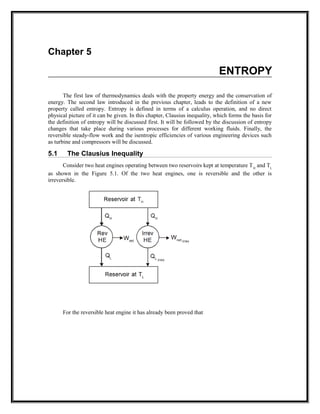
5.1 The Clausius Inequality
Consider two heat engines operating between two reservoirs kept at temperature TH
and TL
as shown in the Figure 5.1. Of the two heat engines, one is reversible and the other is
irreversible.
For the reversible heat engine it has already been proved that
2. 0
0
=
=−
=
∫ rev
L
L
H
H
L
H
L
H
T
dQ
T
Q
T
Q
T
T
Q
Q
As discussed earlier, the work output from the irreversible engine should be less than that
of the reversible engine for the same heat input QH
. Therefore QL,Irrev will be greater than QL,Rev .
Let us define
QL,Irrev = QL,Rev + dQ
then
0
0
,
,
<
−=
−−=
−=
∫
L
LL
revL
H
H
L
IrevL
H
H
Irrev
T
dQ
T
dQ
T
Q
T
Q
T
Q
T
Q
T
dQ
By combining this result with that of a reversible engine we get
0≤
∫ IrrevT
dQ
... (5.1)
This is known as Clausius inequality.
5.2 Entropy
Clausius inequality forms the basis for the definition of a new property known as entropy.
Consider a system taken from
state 1 to state 2 along a reversible path
A as shown in Figure 5.2. Let the
system be brought back to the initial
state 1 from state 2 along a reversible
path B. Now the system has completed
one cycle. Applying Clausius
inequality we get
3. ∫∫
∫
=
+
=
1
2
2
1
0
0
BA T
dQ
T
dQ
T
dQ
...(5.2)
Instead of taking the system from state2 to state1 along B, consider another reversible path
C. Then for this cycle 1-A-2-C-1, applying Clausius inequality :
∫∫
∫
=
+
=
1
2
2
1
0
0
CA T
dQ
T
dQ
T
dQ
...(5.3)
Comparing 5.2 & 5.3
Hence, it can be concluded that the quantity is a point function, independent of the path
followed. Therefore it is a property of the system. Using the symbol S for entropy we can write
...(5.4)
upon integration we get
S2
− S1
= ... (5.5)
For a reversible process.
5.3 Entropy change for an irreversible process
The relationship between the entropy change and heat transfer across the boundary during
an irreversible processes can be illustrated with a simple cycle composed of two processes, one
of which is internally reversible and the other is irreversible, as shown in Figure 5.3. The
Clausius inequality applied to this irreversible cycle can be written as
Since the process B is internally reversible, this process can be reversed, and therefore
or
...(5.6)
4. As defined in equation 5.5, since the process B being reversible the integral on the left
hand side can be expressed as
...(5.7)
5.4 Temperature - Entropy diagram
In a T-s diagram consider a strip of thickness ds with mean height T as shown in Figure
5.4. Then Tds gives the area of the strip.
For a reversible process the elemental heat transfer
dQ = Tds = Area of the strip
To get the total heat transfer the above equation should be integrated between the limits 1
and 2, so that, we get
...(5.8)
This is equivalent to the area under a curve representing the process in a T-S diagram as
shown in the Fig 5.4.
Note: For an isothermal process S2 − S1 = .
For reversible adiabatic process S2 − S1 = 0.
5.5 Change in Entropy
a) Solids and Liquids
Change in entropy
Where dq = du + pdv
For solids and liquids
pdv = 0
Where c- is the specific heat
...(5.9)
b) For ideal gases change in entropy
Substituting
du = CvdT
We get
5. Upon integration
...(5.10a)
Also
Substituting dh = CpdT
and
We get
Upon integration
...(5.10b)
5.6 Principle of Increase in Entropy
Applying Clausius inequality,
For an isolated system undergoing a process
...(5.11)
Consider a system interacting with its surroundings. Let the system and its surroundings
are included in a boundary forming an isolated system. Since all the reactions are taking place
within the combined system, we can express
or ...(5.12)
Whenever a process occurs entropy of the universe (System plus surroundings) will
increase if it is irreversible and remain constant if it is reversible. Since all the processes in
practice are irreversible, entropy of universe always increases
ie., (∆s)universe>0 ...(5.13)
This is known as principle of increase of entropy.
5.7 Adiabatic Efficiency of Compressors and Turbines
In steady flow compressors and turbines reversible adiabatic process is assumed to be the
ideal process. But due to the irreversibilities caused by friction between the flowing fluid and
impellers, the process is not reversible though it is adiabatic. Percentage deviation of this process
from the ideal process is expressed in terms of adiabatic efficiency.
(a) Compressors :
Since compressors are work consuming devices actual work required is more than ideal
work.
...(5.14)
For compressors handling ideal gases
...(5.15)
(b) Turbines :
6. In turbine due to irreversibilities the actual work output is less than the isentropic work.
...(5.16)
For turbines handling ideal gases
...(5.17)
Solved Problems
Prob : 5.1 A body at 200
o
C undergoes an reversible isothermal process. The heat energy
removed in the process is 7875 J. Determine the change in the entropy of the
body.
System : Closed system
Known : T1 = T2
= 200
o
C
= 473 K
Qrejected = 7875 J
Process : Isothermal
To find : ∆s
Diagram :
Analysis : S2 − S1 = for an isothermal process
=
= − 16.65 J/K.
Comment : Entropy decreases as heat is removed from the system.
Prob : 5.2 A mass of 5 kg of liquid water is cooled from 100
o
C to 20
o
C. Determine the
change in entropy.
System : Closed system
7. Known : Mass of water = 5kg
T1 = 100
o
C = 373 K
T2 = 20
o
C = 293 K
Process : Constant pressure
To find : Change in entropy
Diagrams :
Assumptions : 1) The process is reversible
2) The specific heat of liquid water is constant
Analysis : S2 − S1 = m
For this problem
p2 = p1 & Cp = 4.186
∴ S2 − S1 = 5
= −5.053
Comment : Entropy decreases as heat is removed from the system.
Prob : 5.3 Air is compressed isothermally from 100 kPa to 800 kPa. Determine the
change in specific entropy of the air.
System : Closed/Open
Known : p1 = 100 kPa
p2 = 800 kPa
To find : ∆S - change in Specific entropy
Diagram :
8. Analysis : ∆S =
= − R ln [Since the process is isothermal]
= − 0.287 x ln
= − 0.597 kJ/kgK.
Prob : 5.4 A mass of 5 kg of air is compressed from 90 kPa, 32
o
C to 600 kPa in a
polytropic process, pV
1.3
= constant. Determine the change entropy.
System : Closed / Open
Known : p1 = 90 kPa
T1 = 32
o
C = 305 K
p2 = 600 kPa
m = 5 kg
Process : pV
1.3
= Constant
To find : ∆S - Change in entropy
Diagram :
Analysis : S2 − S1 = m
Where T2 = T1
= 305
= 473 K
∴ S2 − S1 = 5
= − 0.517 kJ/K.
Comment : For air the ratio of Cp and Cv is equal to 1.4. Therefore the polytropic
index n = 1.3(<1.4) indicates that some heat is removed from the system
resulting in negative entropy.
Prob : 5.5 A rigid insulated container holds 5 kg of an ideal gas. The gas is stirred so that
its state changes from 5 kPa and 300 K to 15 kPa. Assuming Cp = 1.0 kJ/kgK
and γ = 1.4, determine the change of entropy of the system.
System : Closed
9. Process : Constant volume since the gas is stirred in an rigid container
Known : p1 = 5 kPa p2 = 15 kPa
m = 5 kg Cp = 1.0 kJ/kgK
T1 = 300 K γ = 1.4
Diagrams :
To find : Change in entropy
Analysis : S2 − S1 = m
By applying the state equation.
Since V2 = V1
Also R = Cp − Cv
=
=
=
= 0.286 kJ/kgK
Substituting these values we get
S2 − S1 = 5
= 3.922 kJ/K
Comment : Though this process is adiabatic it is not isentropic since the process of stirring
is an irreversible process.
Prob : 5.6 An insulated rigid vessel is divided into two chambers of equal volumes. One
chamber contains air at 500 K and 2 MPa. The other chamber is evacuated. If
the two chambers are connected d, what would be the entropy change ?
System : Closed system
Process : Unresisted expansion
Known : T1 = 500 K
10. p1 = 2 × 10
3
kPa
To find : Entropy change
Diagrams :
Analysis : s2 − s1 =
s2 − s1 =
After expansion air will occupy the entire volume of the container.
∴ V2 = 2V1
Also 1
W2
= 0 since it is an unresisted expansion
Q12
= 0 since the vessel is insulated
Applying the first law of thermodynamics
Q12
= ∆U + 1
W2
Therefore ∆u = 0
For air
mcv
(T2
− T1
) = 0
i.e. T2
= T1
Hence s2
− s1
= Cv
ln + Rln
= 0.287 ln
= 0.199 kJ/kgK
Comment : Though the process is adiabatic entropy increases as the process involving
unresisted expansion is an irreversible process. It also proves the fact
that
Prob : 5.7 An adiabatic chamber is partitioned into two equal compartments. On one side
there is oxygen at 860 kPa and 14
o
C. On the other side also, there is oxygen,
but at 100 kPa and 14
o
C. The chamber is insulated and has a volume of 7500
cc. The partition is abruptly removed. Determine the final pressure and the
change in entropy of the universe.
System : Closed
Process : Adiabatic Mixing
Known :
Subsystem I Subsystem II
11. Fluid Oxygen Oxygen
Initial pressure 850 kPa 100 kPa
Initial Temperature 14
o
C 14
o
C
Initial volume
Diagrams :
Analysis : Here the energy interaction is taking place only between the two fluids and
therefore the energy lost by one fluid should be equal to the energy gained by
the other fluid. Taking tF
as the final temperature we get
Since the same fluid is stored in both the systems at the same temperature
C1
= C2
and
t1
= t2
= 14
o
C
Therefore the final temperature will also be 14
o
C
After removing partition total mass of oxygen is occupying the entire 7500cc at
14
o
C. Hence the final pressure can be computed as given below :
= 0.0427 kg
= 0.00503 kg
To find the final pressure
= m1
+ m2
= 475 kPa
∆Ssystem
= ∆S1
+ ∆S2
∆Ssurroundings
= 0
∆Suniverse
= 8.596
Prob : 5.8 Two vessels, A and B each of volume 3 m
3
may be connected by a tube of
negligible volume. Vessel A contains air at 0.7 MPa, 95
o
C while vessel B
contains air at 0.35 MPa, 205
o
C. Find the change of entropy when A is
12. connected to B by working from the first principles and assuming the mixing
to be complete and adiabatic.
System : Closed
Process : Adiabatic mixing
Known : Properties Subsystem A Subsystem B
Fluid Air Air
pressure 0.7 MPa 0.35 MPa
volume 3 m
3
3 m
3
Temperature 95
o
C 205
o
C
Diagrams :
Analysis : Since the energy interaction is taking place only between the two fluids energy
lost by one fluid is equal to the energy gained by the other fluid.
∴ QA = QB
Taking t2 as the final temperature after mixing maCa (t2 − t1a) = mbCb(t1b −t2) Since
in both A and B the same fluid is stored, Ca = Cb
Also ma =
=
= 19.9 kg
mb =
=
13. = 7.65 kg
19.9 (t2 − 95) = 7.65 (205 − t2)
2.6 (t2 − 95) = (205 − t2)
2.6t2 + t2 = 205 + 2.6 × 95
t2 = 125.6
o
C
Entropy change = ∆SA + ∆SB
∆SA = mA
∆SB = mB
∆Ssys = 5.08 + 0.525
= 5.605
∆Ssurr = 0
∴ ∆Suniverse = 5.605
Final pressure p2 =
=
= 525 kPa
Prob : 5.9 Air enters a turbine at 400
o
C, 30 bar and velocity 160 m/s. It leaves the turbine
at 2 bar, 120
o
C and velocity 100 m/s. At steady state it develops 200 kJ of work
per kg of air. Heat transfer occurs between the surroundings and the turbine
at an average temperature of 350 K. Determine the rate of entropy generation.
System : Open
Process : Steady flow
Known : Properties Inlet Outlet
Pressure 30 bar 2 bar
Velocity 160 m/s 100 m/s
Temperature 400
o
C 120
o
C
Ambient temperature = 350 K
Work output = 200 kJ/kg
Diagram :
14. To find : Rate of entropy generation
Analysis :
For unit mass = Cp
ln
= 1.005 ln
= 0.236 kJ/kgK
where Qsur
=
=
Qsur
= +89.2 kJ/kg
(∆S)sur
=
= 0.255 kJ/kgK
= 0.019 kJ/kgK.
Prob : 5.10 A turbine operating at steady state receives air at a pressure of p1 =
3.0 bar and temperature of 390 K. Air exits the turbine at a
pressure of p2 = 1.0 bar. The work developed is measured as 74 kJ/kg
of air flowing through the turbine. The turbine operates adiabatically,
and changes in kinetic and potential energy between inlet and exit can
be neglected. Using ideal gas model for air, determine the turbine
efficiency.
System : Open
Process : Steady flow
Known : p1 = 3.0 bar p2 = 1.0 bar
T1 = 390 K Wa = 74 kJ/kg
Diagrams :
Analysis : ηt =
= for an ideal gas
Where
∴ T2s =
15. ∴ T2s = 284.9 K
= Cp ( T1 − T2 ) = 74
∴ T1 − T2 =
= 73.63 K
Hence ηt =
=
= 0.7 (or 70%).
Prob : 5.11 A closed system is taken through a cycle consisting of four reversible processes.
Details of the processes are listed below. Determine the power developed if the
system is executing 100 cycles per minutes.
Process Q (kJ) Temperature (K)
Initial Final
1 - 2 0 300 1000
2 - 3 +1000 1000 1000
3 - 4 0 1000 300
4 - 1 - 300 300
System : Closed
Process : The system is executing cyclic process.
Known : Heat transfer in process 12, 23 and 34 and temperature change in all the process.
No of cycles per minute.
To find : Power developed.
Diagrams :
Analysis : To find the power developed Wnet per cycle must be known. From I Law Wnet =
Qnet which can be computed from the following table
16. Process Q (kJ) Temperature (K)
Initial Final
1 - 2 0 300 1000 0
2 - 3 1000 1000 1000
3 - 4 0 1000 300 0
4 - 1 - 300 300 ∆S41
For a cyclic process Σ∆φ = 0
where φ is any property
∴ Σ∆S = 0
(i.e.,) ∆S12 + ∆S23 + ∆S34 + ∆S41 = 0
0 + 1 + 0 + ∆S41 = 0
∆S41 = −1
Since the process 4-1 is isothermal
= −1
Q41 = −300 kJ
Therefore
Qnet = Q12 + Q23 + Q34 + Q41
= 0 + 1000 + 0 − 300
= 700 kJ per cycle
∴ Wnet = Qnet = 700 kJ
and power developed =
= 700
= 1166.7 kW
Prob : 5.12 Two kilogram of air is heated from 200
o
C to 500
o
C at constant pressure.
Determine the change in entropy.
System : Open/closed
Working : Air
fluid
Process : Constant pressure heating
Known : 1) t1 = 200
o
C
2) t2 = 500
o
C
17. Diagram :
To find : Change in entropy ∆S
Analysis : ∆S =
=
=
= 0.987 kJ/K
Prob : 5.13 A Carnot engine operated between 4
o
C and 280
o
C. If the engine produces 300
kJ of work, determine the entropy change during heat addition and heat
rejection.
System : Open/closed
Process : The working fluid is executing Carnot cycle
Known : 1) t1 = 280
o
C
2) t2 = 4
o
C
3) W = 300 kJ
Diagram :
To find : 1) ∆S during heat addition
2) ∆S during heat rejection
Analysis : 1) In carnot engine heat is added at constant temperature
Therefore ∆S =
Where Qin =
η =
=
= 0.499
Therefore Qin =
= 601.1 kJ
∆S =
=
= 1.087 kJ/K
2) In carnot engine heat rejection is also taking place at constant temperature
Therefore ∆S =
Where Qout = Qin − W
= 601.1 − 300
= 301.1 kJ
∆S =
18. = −1.087 kJ/K
Comment : In a carnot change two isothermal process and two isentropic process.
Therefore ∆S during heat addition must be equal to ∆S during heating
rejection so that
which obeys Clausius Inequality.
Prob : 5.14 Air flows through a perfectly insulated duct. At one section A the pressure and
temperature are respectively 2 bar 200
o
C and at another section B further
along the duct the corresponding values are 1.5 bar and 150
o
C. Which way the
air flowing?
System : Open
Process : Steady flow process
Known : 1) p1 = 2 bar
2) t1 = 200
o
C
3) p2 = 1.5 bar
4) t2 = 150
o
C
To find : To know flow direction
Diagram :
Analysis : This problem cannot be solved by simple application of first law of
thermodynamics. Because there is nothing to tell us whether the fluid is
expanding from A to B or being compressed from B to A.
However, since the duct is insulated the inference is that there is no heat
transfer to or from the environment and therefore there is no change of
entropy in the environment. But in any real process change of entropy of the
system plus the surroundings must be positive. In otherwords ∆SAB > 0
Thus SA > SB and the flow is from B to A.
Even though entropy cannot be measured directly it can still be used to find
the sense of flow in a well insulated duct given two salient states as above.
Prob 5.15 : A certain fluid undergoes expansion in a nozzle reversibly and
adiabatically from 500 kPa, 500 K to 100 kPa. What is the exit velocity?
Take γ = 1.4 and R = 0.287 .
System : Open
19. Process : Reversible adiabatic expansion
Known : 1) Inlet pressure = 500 kPa
2) Inlet temperature = 500 K
3) Exit pressure = 100 kPa
4) The ratio of Specific heats = 1.4
5) Characteristic Gas constant = 0.287
To find : Exit velocity
Diagram :
Analysis : Applying Steady Flow Energy Equation
Therefore
where Cp
and T2
are unknowns.
To find CP
CP
− CV
= R
Substituting γ and R we get
To find T2
It is stated in the problem that the process of expansion is reversible.
Therefore
Also the process is given as adiabatic. That is
(or) ds = 0
S2
− S1
= 0
20. = 315.8 K
Substituting numerical values for T2
and Cp
, we get
Prob 5.16 : Show from the first principle that, for a perfect gas with constant
specific heat capacities expanding polytropically (pvn
= constant) in a
non-flow process, the change of entropy can be expressed by
Gaseous methane is compressed polytropically by a piston from 25o
C
and 0.8 bar to a pressure of 5.0 bar. Assuming an index of
compression of 1.2, calculate the change of entropy and workdone, per unit
mass of gas. The relative molecular weight of methane is 16 and γ = 1.3.
System : Closed
Process : Polytropic (pVn
= C)
Known : 1) T1
= 298 K
2) p1
= 80 kPa
3) p2
= 500 kPa
4) n = 1.2
5) M = 16
6) γ = 1.3
To find :
1) 1
W2
− Work done
2) ∆S − Change in entropy
Analysis : a) To prove S2
− S1
=
From First Law of Thermodynamics
Q12
= 1
W2
+ ∆U
In differential form
for a polytropic process
Therefore
Upon integration we get
From the process relation
21. Substituting for we get
We know that R = CP
− CV
R = CV
(γ − 1)
Substituting for CV
we get
(2) Workdone
= 404.45 K
Substituting numerical values
(3) Change in entropy
Comment : The negative sign in work indicates that work is given into the system.
The negative sign in entropy change indicates that there is a heat rejection
by the system to the ambient during compression.
Prob 5.17 : A closed system undergoes the internally reversible process as shown
below :
Compute the heat transfer.
System : Closed
Process : Defined by a straight line on a T-S diagram.
Known : T1
= 200 K
T2
= 600 K
S1
= 1 kJ/K
S2
= 3 kJ/K
To find : Heat transfer
22. Analysis : Q = Area under the curve representing the process in a T-S diagram
= 800 kJ
Prob 5.18 : In a refrigerant condenser superheated vapour of ammonia enters
steadily at 1.4 MPa, 70o
C. It leaves the condenser at 20o
C. At 1.4 MPa
condensation begins and ends at 36.28o
C. Cooling water enters the
condenser at 10o
C and leaves 15o
C. Determine
(a) the amount of heat rejected per kg of ammonia vapour condensed
for the given inlet and exit conditions.
(b) mass of water to be supplied for each kg of ammonia vapour
condensed
(c) the change in specific entropy of ammonia
(d) the entropy generation per kg of ammonia
Take Cpvapour
= 2.9 kJ/kgK, Cpliquid
= 4.4 kJ/kgK and latent heat of
evaporation of ammonia at 1.4 MPa is 1118 kJ/kg. Also represent
the process in a T-s diagram.
System : Open
Process : Steady flow process
Known : T1
= 70o
C
P1
= 1.4 MPa
T2
= 20o
C
TW
1
= 10o
C
TW
2
= 15o
C
To find : (a) the amount of heat rejected per kg of ammonia vapour condensed
for the given inlet and exit conditions.
(b) mass of water to be supplied for each kg of ammonia vapour
condensed
(c) the change in specific entropy of ammonia
(d) the entropy generation per kg of ammonia
Diagrams :
23. Analysis : (a) Heat rejected per kg of ammonia
Q1−2
= Q1 − 2a
+ Q2a − 2b
+ Q2b − 2
= 2.9 (70 − 36.28) + 1118 + 4.4 (36.28 − 20)
= 1287.42 kJ/kg
(b) Water flow rate required per kg of ammonia
= 61.51
(c) Change in Specific entropy of ammonia
= ∆S1 − 2a
+ ∆S2a − 2b
+ ∆S2b − 2
= − 4.153
(d) ∆Suniverse
= ∆SWater
+ ∆Sammonia
where ∆SWater
= mCp
ln
= 61.51 × 4.186 × ln
= 4.509
Substituting the values we get
∆Suniverse
= 4.509 + (− 4.153)
= 0.356
Comment : As heat is removed from ammonia its entropy decreases whereas
entropy of water increases as it receives heat. But total entropy
change will be positive as heat is transferred through finite temperature
difference.
Prob 5.19 : The specific heats of a gas are given by CP
= a + kT and CV
= b + kT,
where a, b and k are constants and T is in K. Show that for an
isentropic expansion of this gas
Tb
νa−b
ekT
= constant
System : Closed
Process : Isentropic
Known : 1) CP
= a + kT
2) CV
= b + kT
To prove : Tb
νa − b
ekT
= constant for an isentropic process
Proof : For a gas
24. CP
− CV
= (a + kT) − (b + kT)
(or) R = a − b
For an isentropic process
ds = 0
(or)
Substituting for CV
and R
Upon integration
blnT + KT + (a − b) lnν = constant
Taking antilog
Tb
eKT
νa − b
= constant
Prob 5.20 : Calculate the entropy change of the universe as a result of the following
process :
(a) A metal block of 0.8 kg mass and specific heat capacity 250 J/kgK
is placed in a lake at 8o
C
(b) The same block, at 8o
C, is dropped from a height of 100 m into the
lake.
(c) Two such blocks, at 100o
C and 0o
C, are joined together.
Case (a)
System : A metal block
Process : Cooling the metal block by dipping it in a lake.
Known : 1) Initial temperature of the block (T1
)=100 + 273 = 373 K
2) Final temperature of the block (T2
) = 8 + 273 = 281 K
3) Mass of the metal block (m) = 0.8 Kg
4) Specific heat capacity of the metal block (C) = 250
To find : Entropy change of the universe
Diagram :
Analysis : ∆Suniverse
= ∆Ssystem
+ ∆Ssurroundings
25. Where
Where Qsur
= − Qsys
= − mC (T2
− T1
)
= − 0.8 × 250 (281 − 373)
= 18400 J
Substituting the values we get
∆Suniverse
= −56.6 + 65.48
= 8.84 J/K
Comment : As discussed earlier the entropy change of the universe is positive.
The reason is the irreversible heat transfer through finite temperature
difference from the metal block to the lake.
Case (b)
System : A metal block
Process : Falling of the metal block into the lake and reaching equilibrium
Known : 1) Initial Temperature = 281 K
2) Final Temperature = 281 K
3) Initial height = 100 m
4) mass of the metal block (m) = 0.8 kg
5) Specific heat capacity of the metal block (C) = 250 J/kgK
Diagrams :
Analysis : ∆Suniverse
= ∆Ssystem
+ ∆Ssurroundings
26. Where ∆Ssystem
= 0, as the system is at the same temperature at both the
initial and final state.
Qsurroundings
= ∆Esystem
= mgh
= 0.8 × 9.81 × 100 = 784.8 J
Comment : Increase in entropy of the universe indicates that there is a irreversibility
or degradation of energy. That is the high grade potential energy is
converted low grade energy during this process.
Case (c)
Systems : Two metal blocks
Process : Two metal blocks are brought in thermal contact and allowed to reach
equilibrium.
Known : Initial temperatures of the blocks
T1
a = 373 K
T1
b = 273 K
To find : Entropy change of the universe
Diagrams :
Analysis : ∆Suniverse
= ∆Sa
+ ∆Sb
Where
To find T2
Qa
= − Qb
mc (T2
− T1a
) = − mc (T2
− T1
b)
Comment : In this process also the heat transfer through finite temperature
difference makes the process irreversible which in turn results in
increase in entropy of the universe.
27. Prob 5.21 : Each of three identical bodies satisfies the equation U = CT, where C
is the heat capacity of each of the bodies. Their initial temperatures
are 200 K, 250 K and 540 K. If C = 8.4 kJ/K, what is the maximum
amount of work that can be extracted in a process in which these
bodies are brought to a final common temperature ?
System : Three identical bodies
Process : Extracting work with heat transfer among the three bodies so that they
reach a common temperature.
Known : Initial temperature of the three bodies
T1a
= 540 K
T1b
= 250 K
T1c
= 200 K
Heat capacity of all the three bodies = 8.4 T
To find : The maximum amount of work that can be extracted.
Diagram :
Analysis : Let us assume that the final temperature is greater than 250 K, so that
heat is transferred from body (1) to bodies (2) and (3).
The net work obtained
W = Q1
− Q2
− Q3
= (∆U)1
− (∆U)2
− (∆U)3
= C [(540 − T2
) − (T2
− 250) − (T2
− 200)]
= 8.4 [990 − 3T2
]
This work will be maximum if the process under consideration is
reversible. Therefore
∆S1
+ ∆S2
+ ∆S3
= 0
Therefore T2
= 300 K
28. This is the condition for the process to be reversible. Hence the maximum work that can
be obtained is
Wmax
= 8.4 (990 − 3 × 300)
= 8.4 (90)
= 756 kJ
Prob 5.22 : A resistor of 50 ohm resistance carries a constant current of 5A. The
ambient temperature and the temperature of the resistor remain to
be 27o
C over a period of 10 seconds. What is the entropy change of the
resistor, ambient and the universe ?
System : A resistor
Process : Passing of the electrical current through a resistor at constant
temperature.
Known : 1) Initial and final temperature of the resistor = 300 K
2) Ambient Temperature = 300 K
3) Duration (τ) = 10 seconds
To find :
1) ∆Sresistor
2) ∆Sambient
3) ∆Suniverse
Analysis :
∆Suniverse
= ∆Sresistor
+ ∆Sambient
= 0 + 41.7
= 41.7
Comment : When current passes through a resistor it is converted into heat. As the
resistor is to be maintained at the same temperature the heat is dissipated
into the ambient and hence the process is irreversible resulting in
increase of entropy of the universe.
Prob 5.23 : A closed system is assumed to have a heat capacity at constant volume
where a = 0.002 and T is the temperature in K.
The system is originally at 600 K and a thermal reservoir at 300 K is
available. What is the maximum amount of work that can be
recovered as the system is cooled down to the temperature of the reservoir ?
System : A closed system
29. Process : Obtaining work with the help of the heat transfer from the system to
the reservoir.
Known : 1) Cv
= e0.002T
2) T1
= 600 K
3) T2
= 300 K
To find : Wmax
Diagram :
Analysis : Q1
= ∆U
If the work is to be maximum, the process must be reversible. Therefore
(∆S)universe
= 0
∆Ssystem
+ ∆Sreservoir
= 0
Neglecting higher order terms,
Therefore ∆Sreservoir = −∆S system
= 1.731
Thus maximum work = Q1 − Q2
= 911 − 519.3
= 391.7 kJ
30. Exercises
1. = 0 for ____________ processes
Ans : Reversible
2. Entropy is a point function (True / False)
Ans : True
3. Entropy change of universe can never be negative (True / False)
Ans : True
4. All the isentropic processes are reversible adiabatic processes (True / False)
Ans : False
5. What is the difference between adiabatic and isentropic process?
6. A system is losing 500 kJ of heat at a constant temperature of 500 K. What is the change
in entropy ?
7. Area under any curve in T-s diagram represents ____________.
Ans : heat
8. p = constant lines are steeper than v = constant lines in T-S diagram (True/False)
Ans : False
9. During throttling process entropy ____________ (Increases / Decreases) for an ideal gas.
Ans : Increases
10. Find the entropy change of the universe when 1000 kJ of heat is transferred from 800 K to
500 K.
11. Give the expression for change in entropy during isothermal processes and polytropic
processes.
12. Calculate the change in entropy per kg of air when it expands isothermally from 6 bar
to 3bar.
13. A closed system undergoes an adiabatic process. Work done on the system is 15 kJ/kg.
The entropy change of the system
a) is positive
b) is negative
c) can be positive or negative
Ans : positive
14. Give the interpretation of entropy from microscopic point of view.
15. A quantity of gas has an initial pressure, volume and temperature of 140 kPa, 0.14 m
3
and 25
o
C respectively. It is compressed to a pressure of 1.4 MPa according to the law
pV
1.25
= C. Determine the change in entropy
Take cp = 1.041 kJ/ kgK, cv = 0.743 kJ/kgK.
Ans : − 0.207 kJ/kgK
31. 16. 1 kg of air has a volume of 56 litres and a temperature of 190
o
C. The air then receives heat
at constant pressure until its temperature becomes 500
o
C. From this state the air rejects
heat at constant volume until its pressure is reduced to 700 kPa. Determine the change of
entropy during each process, stating whether it is an increase or decrease.
Ans : 0.516 kJ/kgK, an increase − 0.88 kJ/kgK, an decrease
17. A quantity of gas has an initial pressure, volume and temperature of 1.1 bar, 0.16
m
3
and 18
o
C respectively. It is compressed isothermally to a pressure of 6.9 bar.
Determine the change of entropy. Take R = 0.3 kJ/kgK.
Ans : −0.111 kJ/K
18. A reversible heat engine shown in figure below operates between three constant
temperature reservoirs at 600 K, 400 K and 300 K.
It receives 2500 kJ of energy of heat from the reservoir at 600 K and does 1000 kJ of
work. Determine the heat interactions with the other two reservoirs.
Ans : Q2 = 1008, Q3 = 4926
19. A block of copper with a mass of 1.5 kg is initially at 700 K. It is allowed to cool by
means of heat transfer to the surrounding air at 300 K. Determine the change in entropy of
the copper and change in entropy of the universe after copper reaches thermal equilibrium.
Assume specific heat of copper is 0.39 kJ/kgK.
Ans : − 0.4967 kJ/K, +0.2843 kJ/K
20. Using the principle of increase in entropy prove that the heat transfer is always from a
high-temperature body to a low temperature body.
21. Nitrogen at 420 K and 1.4 MPa is expanded reversibly and adiabatically in a nozzle to exit
pressure of 700 kPa. Determine the temperature and velocity of the nitrogen at the exit of
the nozzle. Take γN2 = 1.40.
32. 22. A vessel is divided into two temperature by means of a membrane as shown in the figure
given below. What will be the final state of air and change in entropy of the universe if the
membrane is removed.
Ans : Pf = 750.14 kPa, Tf = 65.11
o
C = 0.373
23. A given gaseous system undergoes an isentropic process from state1 to state 2.
a) Combine the two relations pv = RT and pv
γ
= C and show that
b) Integrate the two expressions, using pv
γ
= C and show that is γ times by comparison.
24. During the isentropic process of 1.36 kg/s of air, the temperature increases from 4.44
o
C to
115.6
o
C. For a non-flow process and for a steady flow process find
a) Change in internal energy
b) Work done
c) Change in enthalpy
d) Change in entropy and
e) Heat transfer
25 Air at 5 bar,100
o
C, expands reversibly in a piston-cylinder arrangement. It expands to 2
bar in an isothermal process. Calculate
(a) heat transfer per unit mass of air
(b) change in specific internal energy
(c) change in specific entropy
26 One kg of air at 1 bar, 20
o
C, is compressed according to the law pv
1.3
= constant until the
pressure is 5 bar. Calculate the change in entropy and sketch the process on a T-S diagram
indicating the area representing the heat flow.
27 1 kg of air at 1bar, 25
o
C, changes its state to 6 bar and a volume of 1 m
3
. Calculate the
change of entropy and sketch the initial and final state points on the p-v and T-S fields.
28 0.5 m
3
ethane (C2H4) at 7 bar, 260
o
C expand isentropically in a cylinder behind a piston to
1bar, 100
o
C. Calculate the workdone in expansion assuming ethane as perfect gas. The
same mass is now recompressed back to 7 bar according to the law pv
1.35
= constant.
Calculate the final temperature and the heat transfer. Calculate also the change in entropy
and sketch both process on the p-v and T-S fields. Take CP = for
ethane.
33. 29 A mass m of water at T1 is mixed with equal mass of water at T2 at the same pressure in an
insulated mixing chamber. Show that the entropy change of the Universe is given as
30 Consider a closed system consisting of air as working fluid in a piston cylinder
arrangement as shown in the Figure.
The weight placed on the piston is such that the air occupies a volume of 1.5 litre when
there exist thermodynamic equilibrium between the system and its surroundings. The
corresponding pressure and temperature are 2 bar, 30
o
C. Heat is added until the pressure
increases to 5 bar. Volume of air when the piston touches the stop is 3 litres. Find the
following
a) Final temperature
b) Workdone
c) Heat transformed
d) Change in entropy
31 An ideal vapour absorption refrigeration system may be considered as the combination of
the reversible heat engine operating a reversible refrigerator as given in the following
diagram. Obtain the COP of the refrigeration system which is defined as the ratio of Qe to
Qg.
32. Vapour absorption heat transformer is a novel device used for upgrading a portion of
waste heat from low temperature to high temperature. An ideal vapour absorption heat
transformer may be considered as the combination of the reversible heat engine operating
a reversible heat pump as given in the following diagram. Obtain the COP of the vapour
absorption heat transformer which is defined as the ratio of Qa to (Qg + Qe).