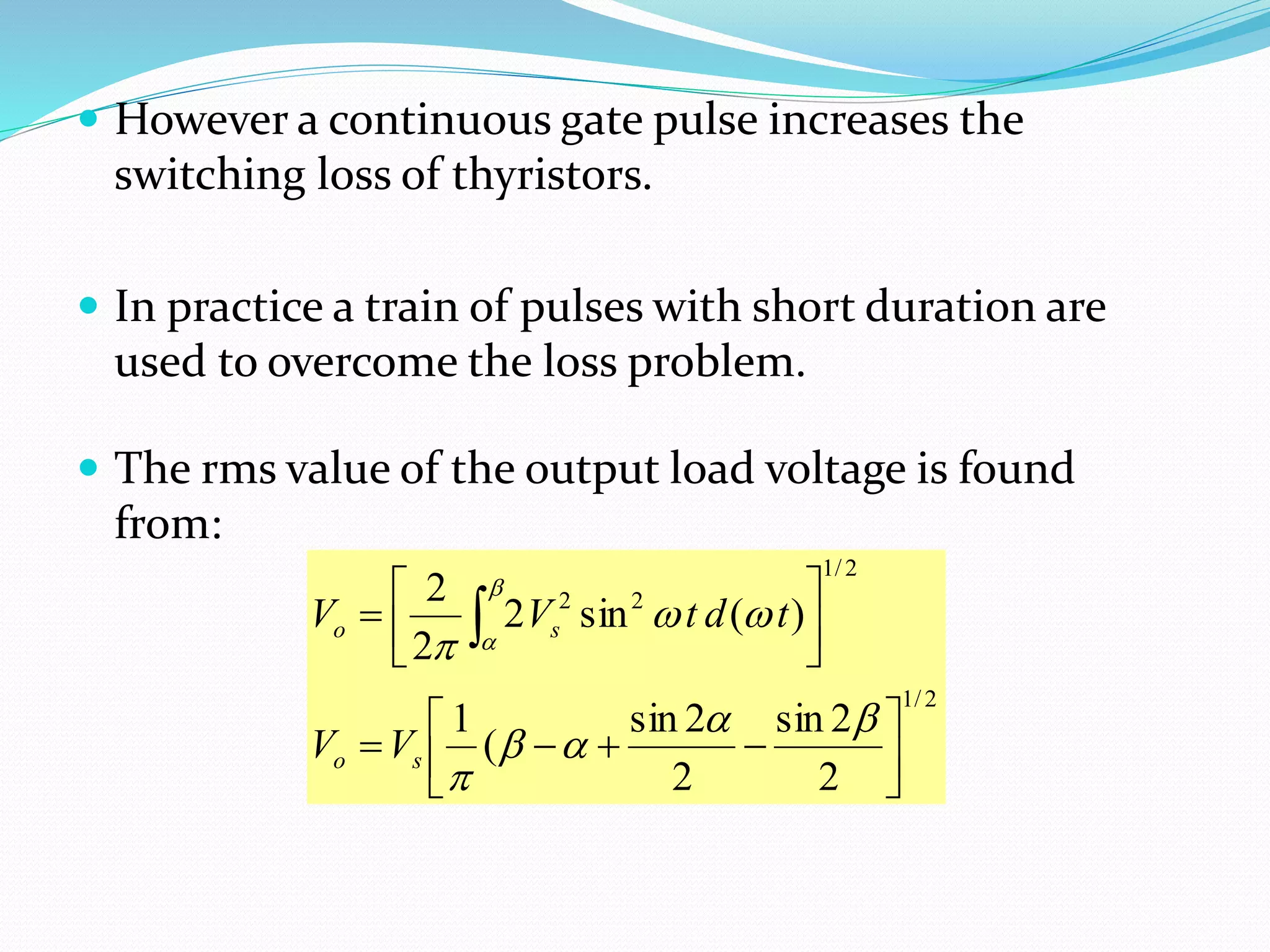
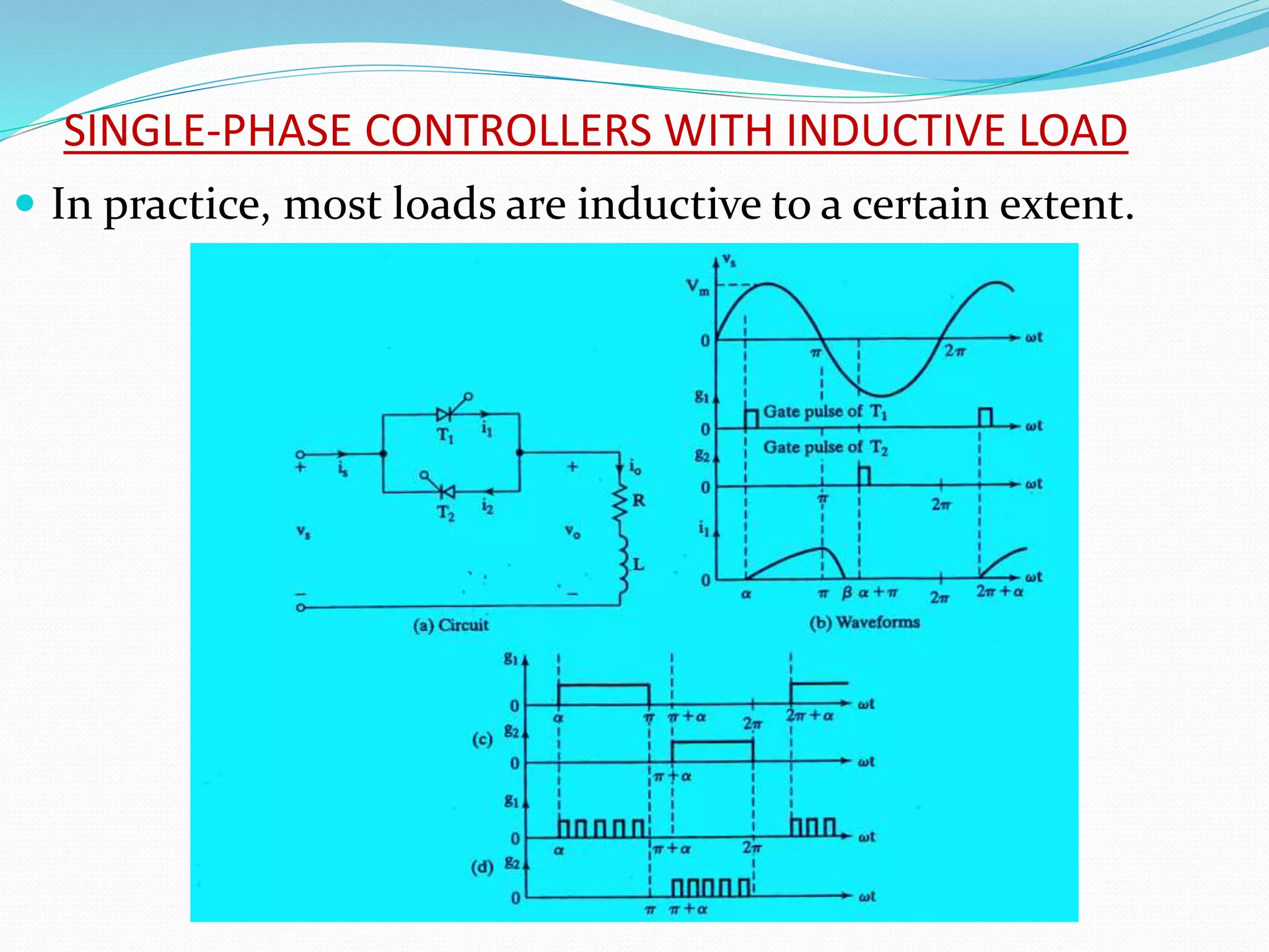
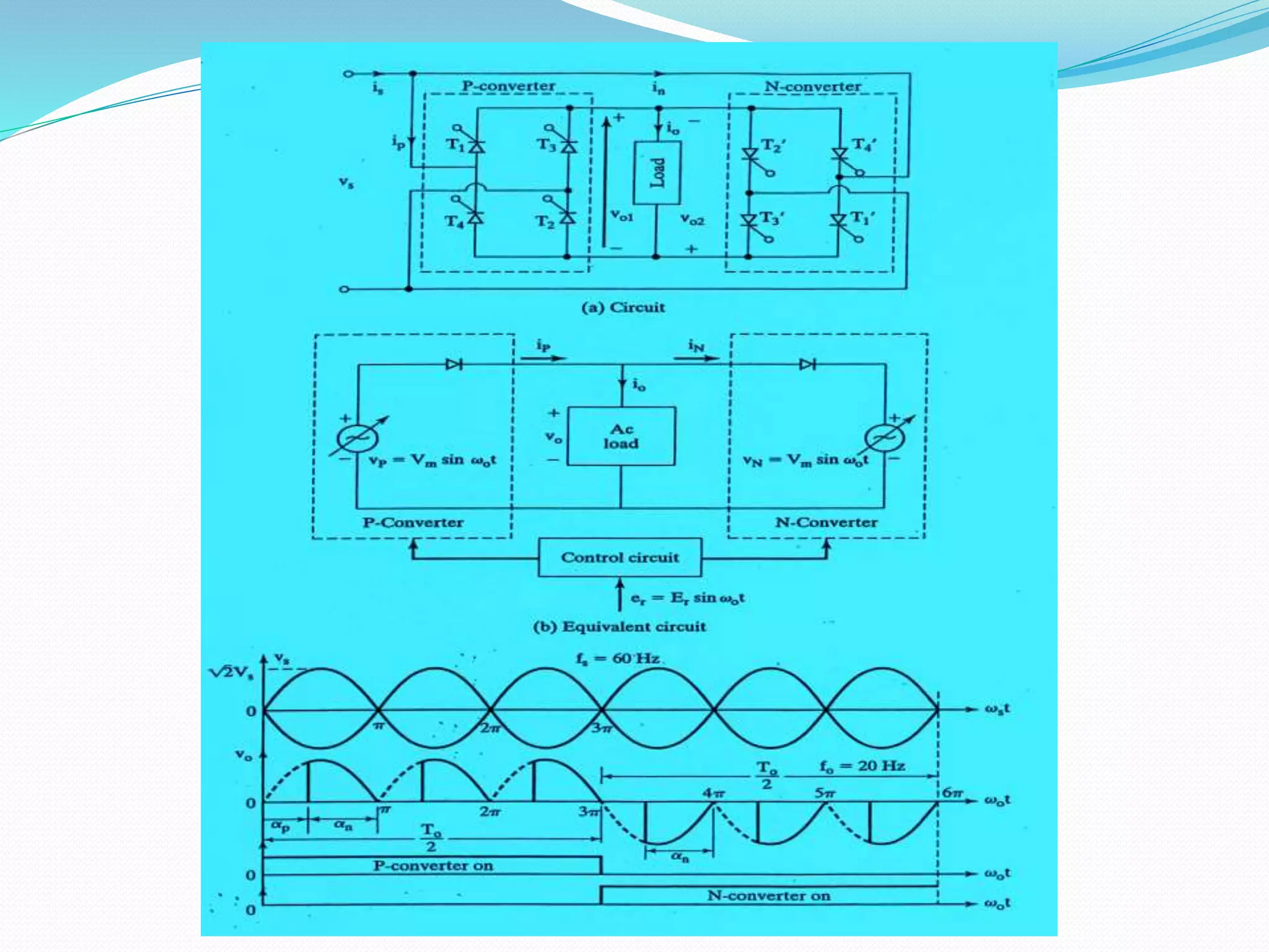
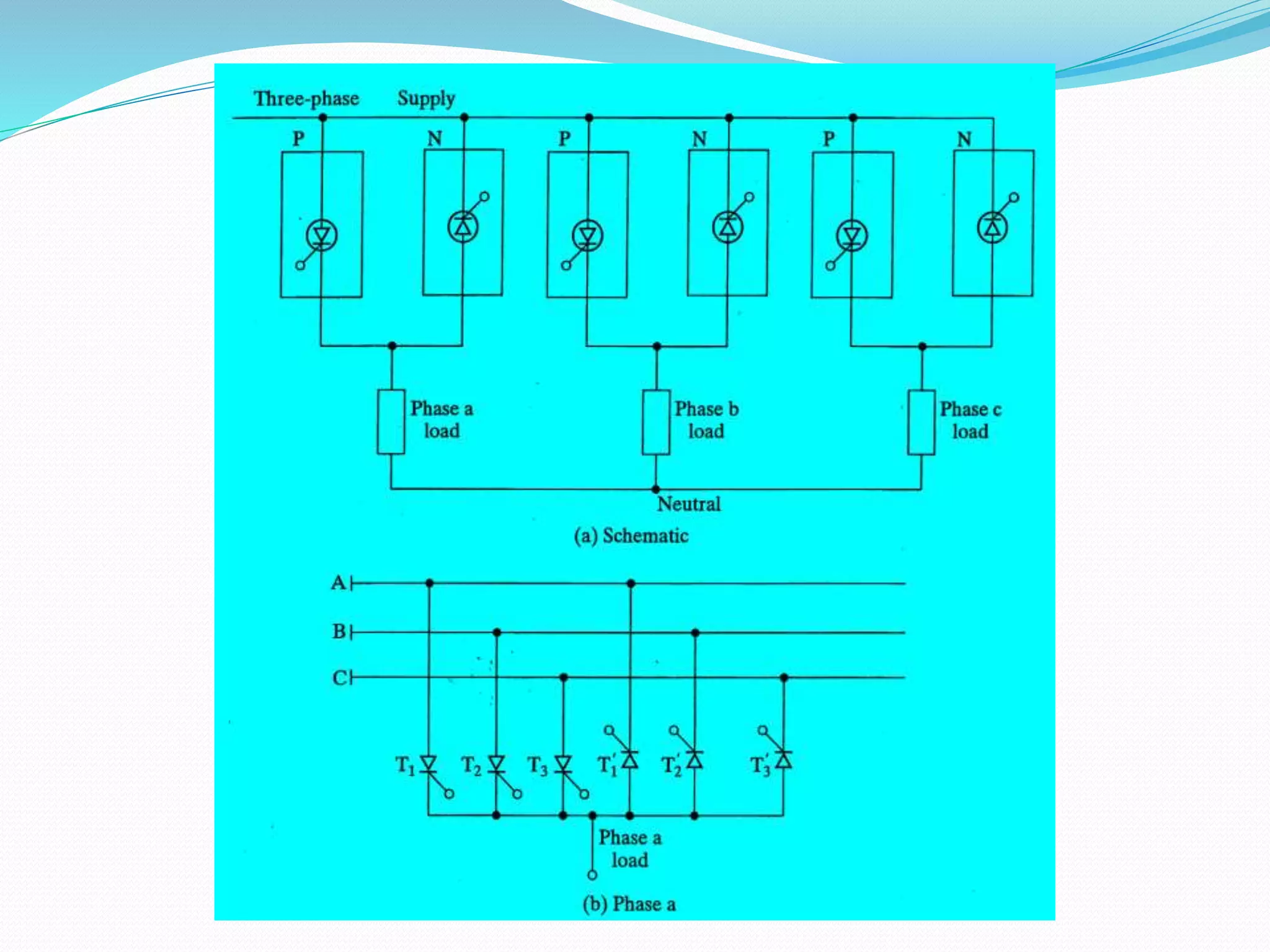
This document discusses different types of AC voltage controllers. It begins by introducing AC voltage controllers and how they can control power flow into a load by varying the RMS value of the load voltage using thyristors. It then describes the main types of AC voltage controllers classified by input supply type and control method. Applications such as lighting, heating and motor speed control are also outlined. The document proceeds to explain the principles and techniques of on-off control and phase control. Circuit diagrams are provided to illustrate single phase and three phase controller configurations. The document concludes by briefly discussing cycloconverters which can provide a variable output voltage and frequency.
These slides provide an elementary description of Power Electronics and its application domains. It also shows the different power devices and converters.
INTRODUCTION
A chopper is a static device which is used to obtain a variable dc voltage from a
constant dc voltage source. A chopper is also known as dc-to-dc converter. The thyristor converter offers greater efficiency, faster response, lower maintenance, smaller size and smooth control. Choppers are widely used in trolley cars, battery operated vehicles, traction motor control, control of large number of dc motors, etc….. They are also used in regenerative braking of dc motors to return energy back to supply and also as dc voltage regulators.
Choppers are of two types
• Step-down choppers
• Step-up choppers.
In step-down choppers, the output voltage will be less than the input voltage
whereas in step-up choppers output voltage will be more than the input voltage.
Classification of Choppers:
(a) Depending upon the direction of the output current and voltage, the converters can be classified into five classes namely Class A [One-quadrant Operation] Class B [One-quadrant Operation] Class C [Two-quadrant Operation] Class D [Two-quadrant Operation] Class E [Four-quadrant Operation]
(b) Based on the output voltage of the output, the choppers are classified as
(i) Step-Down Chopper In this case the average output voltage is less than the input voltage. It is also known as step down converter
(ii) Step-Up Chopper Here the average output voltage is more than the input voltage. It is also known as step up converter
(iii) Step-Up/Down Chopper This type of converter produces an output voltage that is either lower or higher than the input voltage
(c) Depending upon the power loss occurred during turn ON/OFF of the switching device, the choppers are classified into two categories namely
(i) Hard switched Converter Here the power loss is high during the switching (ON to OFF and OFF to ON) as a result of the non zero voltage and current on the power switches.
(ii) Soft switched or resonant converters In this type of choppers, the power loss is low at the time of switching as a result of zero voltage and/or zero current on the switches.
2
PRINCIPLE OF STEP-DOWN CHOPPER
Figure 2.1 shows a step-down chopper with resistive load. The thyristor in the
circuit acts as a switch. When thyristor is ON, supply voltage appears across the load and
when thyristor is OFF, the voltage across the load will be zero. The output voltage and
current waveforms are as shown in figure 2.2.
It’s a power electronics project. It is able to give output voltage(DC) more and less than input voltage as per requirement.
We can generate variable DC voltage which is less than input, but, the special things about this converter is, it has capability to produce variable DC voltage as high as twice the input voltage.
We have specially designed and manufactured inductor for this project.
As we have discussed that out of various triggering methods to turn the SCR, gate triggering is the most efficient and reliable method. Most of the control applications use this type of triggering because the desired instant of SCR turning is possible with gate triggering method.
Generation of High D.C. Voltage (HVDC generation)RP6997
Generation of high dc voltage using different methods like half wave and full wave rectifier, voltage doubler circuits, voltage multiplier circuits, cockcroft-walton circuits and van de graaff generators.
Power Electronics - Phase Controlled Converters.pptxPoornima D
A detailed analysis of the Controlled Converters with SCR. it contains a single-phase Fully controlled- Half Wave and Full Wave Rectifier with R, RL and RLC loads., Three Phase Fully controlled- Half Wave and Full Wave Rectifier with R, RL and RLC loads. Dual Converters. It also explains the effect of source inductance on the performance of converters
There are numerous systems in use today that convert the fixed
voltage and fixed frequency a.c. supply into variable voltage or /and variable frequency supply using power semiconductor devices. The simplest forms of ac-to-ac converters are the a.c. voltage controllers that
convert fixed voltage fixed frequency into variable voltage fixed frequency. These voltage controllers are also called a.c. choppers or a.c. voltage regulators. Some of the applications are motor drive systems; electric furnaces heat control, light dimmers, HVAC systems, welding and other industrial applications. This chapter discusses the single phase and three-phase a.c. voltage controller (a.c. choppers) and their performance with resistive and resistive-inductive loads.
The ac-to-ac power converters available in industry today do not actually convert power directly from a.c. power of one frequency to a.c. power of another frequency. Instead, these converters first convert
electrical power to d.c. using a rectifier, and then convert power back into a.c. using an inverter.These are called two-stage converters. However,
a cycloconverter is a frequency changer that converts an a.c. supply of fixed input frequency directly to an a.c. output of another frequency.
Cycloconverters not only eliminate the problem of having multiple systems to perform a single function, they also limit the flow of power to a single switch at any one period in time. Therefore, there is no bus link,
d.c. or otherwise, included in a cycloconverter topology between power input and power output.
Design and Simulation of Low Pass Filter for Single phase full bridge Inverte...IJERA Editor
Sinusoidal pulse width modulation SPWM technique is widely preferred to other modulation techniques as the
Inverter output frequency obtained is equal to the required fundamental frequency. SPWM with unipolar voltage
switching is used as it results in cancellation of harmonic component at the switching frequencyin the output
voltage, also the sidebands of the switching frequency harmonics disappear and in addition to this, other
dominant harmonic at twice the switching frequency gets eliminated. Hence, due to these advantages unipolar
voltage switching with SPWMis used for Inverter switching. In this paper, an in-depth analysis of unipolar
voltage switching technique with SPWM as applied to a single-phase full bridge Inverter is described and
designing of an efficient, active low pass filter LPF is discussed for an particular cut-off frequency,푓푐 and
damping factor zeta, 휁 and the filter is placed at the output side of a single-phase full bridge Inverter and
therefore eliminating the harmonic component from the Inverter output voltage resulting in a pure sinusoidal ac
voltage waveform.
1.SINGLE PHASE HALF WAVE CONTROLLED CONVERTER WITH RESISTIVEINDUCTIVE LOAD
2 SINGLE PHASE FULLY CONTROLLED CONVERTER WITH RESISTIVEINDUCTIVE LOAD
3 SPEED CONTROL OF 3-PHASE SLIP RING (WOUND ROTOR) INDUCTION MOTOR
4 THYRISTORISED DRIVE FOR DC MOTOR WITH CLOSED LOOP CONTROL
5 THYRISTORISED DRIVE FOR PMDC MOTOR WITH SPEED MEASUREMENT & CLOSED LOOP CONTROL
6 SPEED MEASUREMENT OF PMDC MOTOR WITH CLOSED LOOP CONTROL
7 IGBT USING SINGLE 4 QUADRANT CHOPPER DRIVE FOR PMDC MOTOR WITH SPEED MEASUREMENT AND CLOSED LOOP AND CONTROL
8 SINGLE PHASE CYCLO CONVERTER BASED AC INDUCTION MOTOR CONTROLLER
9 THREE PHASE INPUT THYRISTORISED DRIVE 3HP DC MOTOR WITH CLOSED LOOP CONTROL
10 THREE PHASE INPUT IGBT DRIVE FOR 4 QUADRANT CHOPPER OF 3HP DC MOTOR WITH CLOSED LOOP CONTROL
Saudi Arabia stands as a titan in the global energy landscape, renowned for its abundant oil and gas resources. It's the largest exporter of petroleum and holds some of the world's most significant reserves. Let's delve into the top 10 oil and gas projects shaping Saudi Arabia's energy future in 2024.
About
Indigenized remote control interface card suitable for MAFI system CCR equipment. Compatible for IDM8000 CCR. Backplane mounted serial and TCP/Ethernet communication module for CCR remote access. IDM 8000 CCR remote control on serial and TCP protocol.
• Remote control: Parallel or serial interface.
• Compatible with MAFI CCR system.
• Compatible with IDM8000 CCR.
• Compatible with Backplane mount serial communication.
• Compatible with commercial and Defence aviation CCR system.
• Remote control system for accessing CCR and allied system over serial or TCP.
• Indigenized local Support/presence in India.
• Easy in configuration using DIP switches.
Technical Specifications
Indigenized remote control interface card suitable for MAFI system CCR equipment. Compatible for IDM8000 CCR. Backplane mounted serial and TCP/Ethernet communication module for CCR remote access. IDM 8000 CCR remote control on serial and TCP protocol.
Key Features
Indigenized remote control interface card suitable for MAFI system CCR equipment. Compatible for IDM8000 CCR. Backplane mounted serial and TCP/Ethernet communication module for CCR remote access. IDM 8000 CCR remote control on serial and TCP protocol.
• Remote control: Parallel or serial interface
• Compatible with MAFI CCR system
• Copatiable with IDM8000 CCR
• Compatible with Backplane mount serial communication.
• Compatible with commercial and Defence aviation CCR system.
• Remote control system for accessing CCR and allied system over serial or TCP.
• Indigenized local Support/presence in India.
Application
• Remote control: Parallel or serial interface.
• Compatible with MAFI CCR system.
• Compatible with IDM8000 CCR.
• Compatible with Backplane mount serial communication.
• Compatible with commercial and Defence aviation CCR system.
• Remote control system for accessing CCR and allied system over serial or TCP.
• Indigenized local Support/presence in India.
• Easy in configuration using DIP switches.
Democratizing Fuzzing at Scale by Abhishek Aryaabh.arya
Presented at NUS: Fuzzing and Software Security Summer School 2024
This keynote talks about the democratization of fuzzing at scale, highlighting the collaboration between open source communities, academia, and industry to advance the field of fuzzing. It delves into the history of fuzzing, the development of scalable fuzzing platforms, and the empowerment of community-driven research. The talk will further discuss recent advancements leveraging AI/ML and offer insights into the future evolution of the fuzzing landscape.
Courier management system project report.pdfKamal Acharya
It is now-a-days very important for the people to send or receive articles like imported furniture, electronic items, gifts, business goods and the like. People depend vastly on different transport systems which mostly use the manual way of receiving and delivering the articles. There is no way to track the articles till they are received and there is no way to let the customer know what happened in transit, once he booked some articles. In such a situation, we need a system which completely computerizes the cargo activities including time to time tracking of the articles sent. This need is fulfilled by Courier Management System software which is online software for the cargo management people that enables them to receive the goods from a source and send them to a required destination and track their status from time to time.
CFD Simulation of By-pass Flow in a HRSG module by R&R Consult.pptxR&R Consult
CFD analysis is incredibly effective at solving mysteries and improving the performance of complex systems!
Here's a great example: At a large natural gas-fired power plant, where they use waste heat to generate steam and energy, they were puzzled that their boiler wasn't producing as much steam as expected.
R&R and Tetra Engineering Group Inc. were asked to solve the issue with reduced steam production.
An inspection had shown that a significant amount of hot flue gas was bypassing the boiler tubes, where the heat was supposed to be transferred.
R&R Consult conducted a CFD analysis, which revealed that 6.3% of the flue gas was bypassing the boiler tubes without transferring heat. The analysis also showed that the flue gas was instead being directed along the sides of the boiler and between the modules that were supposed to capture the heat. This was the cause of the reduced performance.
Based on our results, Tetra Engineering installed covering plates to reduce the bypass flow. This improved the boiler's performance and increased electricity production.
It is always satisfying when we can help solve complex challenges like this. Do your systems also need a check-up or optimization? Give us a call!
Work done in cooperation with James Malloy and David Moelling from Tetra Engineering.
More examples of our work https://www.r-r-consult.dk/en/cases-en/
Cosmetic shop management system project report.pdfKamal Acharya
Buying new cosmetic products is difficult. It can even be scary for those who have sensitive skin and are prone to skin trouble. The information needed to alleviate this problem is on the back of each product, but it's thought to interpret those ingredient lists unless you have a background in chemistry.
Instead of buying and hoping for the best, we can use data science to help us predict which products may be good fits for us. It includes various function programs to do the above mentioned tasks.
Data file handling has been effectively used in the program.
The automated cosmetic shop management system should deal with the automation of general workflow and administration process of the shop. The main processes of the system focus on customer's request where the system is able to search the most appropriate products and deliver it to the customers. It should help the employees to quickly identify the list of cosmetic product that have reached the minimum quantity and also keep a track of expired date for each cosmetic product. It should help the employees to find the rack number in which the product is placed.It is also Faster and more efficient way.
Final project report on grocery store management system..pdfKamal Acharya
In today’s fast-changing business environment, it’s extremely important to be able to respond to client needs in the most effective and timely manner. If your customers wish to see your business online and have instant access to your products or services.
Online Grocery Store is an e-commerce website, which retails various grocery products. This project allows viewing various products available enables registered users to purchase desired products instantly using Paytm, UPI payment processor (Instant Pay) and also can place order by using Cash on Delivery (Pay Later) option. This project provides an easy access to Administrators and Managers to view orders placed using Pay Later and Instant Pay options.
In order to develop an e-commerce website, a number of Technologies must be studied and understood. These include multi-tiered architecture, server and client-side scripting techniques, implementation technologies, programming language (such as PHP, HTML, CSS, JavaScript) and MySQL relational databases. This is a project with the objective to develop a basic website where a consumer is provided with a shopping cart website and also to know about the technologies used to develop such a website.
This document will discuss each of the underlying technologies to create and implement an e- commerce website.
Sachpazis:Terzaghi Bearing Capacity Estimation in simple terms with Calculati...Dr.Costas Sachpazis
Terzaghi's soil bearing capacity theory, developed by Karl Terzaghi, is a fundamental principle in geotechnical engineering used to determine the bearing capacity of shallow foundations. This theory provides a method to calculate the ultimate bearing capacity of soil, which is the maximum load per unit area that the soil can support without undergoing shear failure. The Calculation HTML Code included.
Vaccine management system project report documentation..pdfKamal Acharya
The Division of Vaccine and Immunization is facing increasing difficulty monitoring vaccines and other commodities distribution once they have been distributed from the national stores. With the introduction of new vaccines, more challenges have been anticipated with this additions posing serious threat to the already over strained vaccine supply chain system in Kenya.
2. INTRODUCTION
The power flow into a load can be controlled by
varying the rms value of the load voltage.
This can be accomplished by thyristors, and this type
of power circuit is known as ac voltage controllers.
AC
Voltage
Controller
V0(RMS)
fS
Variable AC
RMSO/PVoltage
AC
Input
Voltage
fs
Vs
fs
3. TYPE OF AC VOLTAGE CONTROLLERS
Classification based on the type of input ac supply:
Single Phase AC Controllers
Three Phase AC Controllers
Each type of controller may be sub divided into:
Unidirectional or half wave ac controller
Bi-directional or full wave ac controller
In brief different types of ac voltage controllers are:
Single phase half wave ac voltage controller (uni-directional controller)
Single phase full wave ac voltage controller (bi-directional controller)
Three phase half wave ac voltage controller (uni-directional controller)
Three phase full wave ac voltage controller (bi-directional controller)
4. APPLICATIONS OF AC VOLTAGE CONTROLLERS
Lighting / Illumination control in ac power circuits.
Induction heating.
Industrial heating & Domestic heating.
Transformers tap changing (on load transformer tap
changing).
Speed control of induction motors (single phase and
poly phase ac induction motor control).
AC magnet controls.
5. AC VOLTAGE CONTROL TECHNIQUES
two types of control are normally used:
On-off Control
Phase angle control
In on-off control, thyristor switches connect the load to the
ac source for a few cycles of the input voltage and then
disconnected for a few cycles.
In phase control, thyristor switches connect the load to the ac
source for a portion of each cycle.
6. COMMUTATION
Since the input voltage is ac, thyristors are line
commutated.
Typically phase control thyristors which are cheaper
are used.
For applications up to 400 Hz, TRIACs are used.
8. This type of control is applied in applications which
have high mechanical inertia and high thermal time
constant.
Typical examples are industrial heating and speed
control of motors.
9. Note that k is called the duty cycle, and the power
factor and output voltage vary with the square root of
k.
kV
nm
n
VV
tdtV
mn
n
V
ssrmso
srmso
2/1
2
0
22
)(sin2
)(2
If the input voltage is connected to load for n cycles and
is disconnected for m cycles, the output load voltage is
found from:
10. PRINCIPLE OF PHASE CONTROL
The principle of phase control can be explained with
the following circuit.
11. Due to the presence of diode D1, the control range is
limited.
The rms output voltage can only be varied between
70.7 to 100%.
The output voltage and input current are asymmetrical
and contain a dc component.
12. This circuit is a single-phase half-wave controller and
is suitable only for low power resistive loads, such as
heating and lighting.
Since the power flow is controlled during the positive
half-cycle of input voltage, this type of controller is
also known as unidirectional controller.
13. The rms value of the output voltage is :
The average value of the output voltage is:
2/1
2/122
2
22
)]
2
2sin
2(
2
1
[
)]}(sin2)(sin2[
2
1
{
so
sso
VV
tdtVtdtVV
)1(cos
2
2
)](sin2)(sin2[
2
1 2
s
o
ssdc
V
V
tdtVtdtVV
14. SINGLE-PHASE BIDIRECTIONAL CONTROLLERS WITH
RESISTIVE LOADS
The problem of dc input current can be prevented by
using bidirectional or full-wave control.
15. The firing pulse of T1 and T2 are 180 degrees apart.
The rms value of the output voltage is:
By varying α from 0 to π, Vo can be varied from Vs to 0.
2/1
2/1
22
2
2sin
(
1
)(sin2
2
2
so
so
VV
tdtVV
17. The gating signals of thyristors could be short pulses for a
controller with a resistive load.
However, they are not suitable for inductive loads.
When thyristor T2 is fired, thyristor T1 is still conducting due
to the inductive load.
By the time the current of T1 falls to zero and T1 is turned off,
the gate current of T2 has already ceased.
Consequently, T2 will not be turned on.
This difficulty can be resolved by using a continuous gate
signal with a duration of π - α.
18. However a continuous gate pulse increases the
switching loss of thyristors.
In practice a train of pulses with short duration are
used to overcome the loss problem.
The rms value of the output load voltage is found
from:
2/1
2/1
22
2
2sin
2
2sin
(
1
)(sin2
2
2
so
so
VV
tdtVV
19. THREE-PHASE FULL-WAVE CONTROLLERS
The unidirectional controllers, which contain dc input
current and higher harmonic content due to the
asymmetrical nature of the output voltage waveform,
are not normally used in ac motor drives.
A three-phase bidirectional control is commonly used.
23. Since the phase current in a normal three-phase delta
system is only 1/√3 of the line current, the current ratings
of the thyristors are less.
The following figure shows the waveforms for a delay angle
of 120 degrees.
26. CYCLOCONVERTERS
The ac voltage controllers provide a variable output
voltage, but the frequency of the output voltage is
fixed.
In addition the harmonic content is high at low ac
voltages (high α).
A variable output voltage at variable frequency can be
obtained from a two stage conversion.
27. First the fixed ac is converted to a variable dc
(controlled rectifier), and then the variable dc is
converted to a variable ac at variable frequency
(inverter).
However, the cycloconverter can eliminate the need of
one or more intermediate converters.
A cycloconverter is a direct frequency changer that
converts ac power at one frequency to ac power at
another frequency by ac-ac conversion.
28. Cycloconverters are naturally commutated and the
maximum output frequency is a fraction of the source
frequency.
Therefore, cycloconverters are low speed ac motor
drives in ranges up to 15 MW with frequencies from 0 to
20 Hz.
29. SINGLE-PHASE CYCLOCONVERTERS
The principle of operation of single-phase cycloconverters
can be explained with the following figure.
First, two single-phase controlled converters are operated
as bridge rectifiers.
Their delay angles are such that the output voltage of one
converter is equal and opposite to that of the other
converter.
If αp is the delay angle of positive converter, the delay
angle of the negative converter is: αn = π – αp
30.
31. THREE-PHASE CYCLOCONVERTER
The circuit diagram of a three-phase/single phase
cycloconverter is shown next.
The synthesis of output waveform for an output
frequency of 12 Hz is also in this figure.
32.
33. The cycloconverter of previous figure can be extended
to feed a three-phase load, by having six three-phase
converters.
If six full-wave three-phase converters are used, 36
thyristors would be required.
34.
35. REDUCTION OF OUTPUT HARMONICS
The output voltage of cycloconverters is basically made up of segments
of input voltages.
The average value of a segment depends on the delay angle for that
segment.
If the delay angles of segments were varied in such a way that the
average values of segments corresponds as closely as possible to the
variations of desired sinusoidal output voltage, the harmonics on the
output voltage can be minimized.
36. The delay angles for segments can be generated by
comparing a cosine signal at the source frequency with an
ideal sinusoidal reference voltage at the output frequency.
The following figure shows generation of the gating signals
for the cycloconverter.