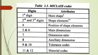
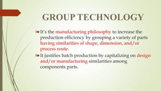
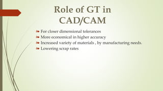
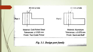
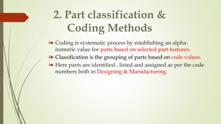
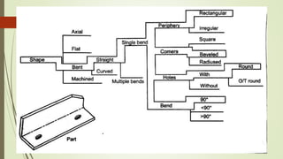
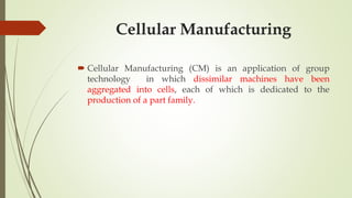
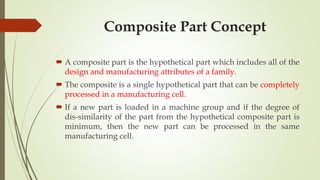
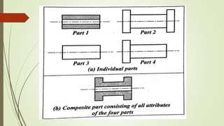
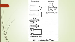
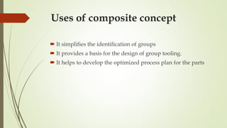
UNIT 5
GROUP TECHNOLOGY
❧It’s the manufacturing philosophy to increase the
production efficiency by grouping a variety of parts
having similarities of shape, dimension, and/or
process route.
❧It justifies batch production by capitalizing on design
and/or manufacturing similarities among
components parts.
Role of GT in
CAD/CAM
❧ For closer dimensional tolerances
❧ More economical in higher accuracy
❧ Increased variety of materials , by manufacturing needs.
❧ Lowering scrap rates
Important Elements of
CAD/CAM Integration
❧ It provides a common data base for effective integration of
CAD & CAM for successful implementation of CIM
❧ GT provides a common language for users
❧ It gives a information about Design, Manufacturing
Attributes, Processes & Capabilities
Part Families
❧ A part family is a collection of parts which are similar in
geometric shape and size or processing steps are required in
their manufacture.
❧ It may be a similar in their Design, Manufacturing
characteristics are grouped and referred as Design part
family & Manufacturing part family
❧ The characteristics used are known as Attributes
Similar manufacturing
process
METHODS FOR PART
FAMILY FORMATION
1.Visual inspection
2. part classification & Coding Methods
3.production flow analysis
1.Visual inspection
❧This is a simplest & least expensive
method
❧Here all are arranged in a similar groups
Visual Inspection
Method
2. Part classification &
Coding Methods
❧ Coding is systematic process by establishing an alpha-
numeric value for parts based on selected part features.
❧ Classification is the grouping of parts based on code values.
❧ Here parts are identified , listed and assigned as per the code
numbers both in Designing & Manufacturing.
Design & Manufacturing
Attributes
1.System based on Part Design Attributes
2.System based on Manufacturing Attributes
3.System based on Both Design & Manufacturing
Attributes
Coding System
Structure
❧A Group Technology is a string of
characteristics capturing information's about
an item.
❧A part coding scheme consists of a sequence
of symbols that identify the part’s Design /
Manufacturing attributes
Types of Basic Code
Structures
❧1. Hierarchical codes
(Mono codes or tree structure)
❧2. Attributes codes
(Poly code or chain type structure)
❧3. Decision tree codes
(hybrid code or mixed codes)
Hierarchical codes
❧The interpretation of each successive symbols
depends on the value of the preceding symbols
❧Each symbols amplifies the information contained in
the preceding digit, so that the digits in the symbols
cannot be interrupt alone.
❧The structure is like a tree.
Attribute Code
❧The interpretation of each symbols in the
sequence does not depend on the value of
preceding symbols.
❧Here each digit in this code represents
information in its own right and does not
directly qualify the information provided by
the other digits.
Decision-Tree Code
❧A hybrid code captures the best features of the
hierarchical & poly code Structures.
❧This system is also known as decision-tree coding
❧In this both the attributes are combined.
❧This is the mostly commonly used coding systems
with combined hybrid constructions.
Reason for using
Coding Scheme
❧ Design Retrievals
❧ Automated Process Planning
❧ Machine Cell Design
Coding Systems
 Through more than 100 coding systems are available, the
following coding systems are widely recognized in industries:
Opitz Classification Systems
❧ The opitz system was developed by H.Optiz of the university of
Aachen in Germany.
❧ It was the most popular and one of the first published
classification and coding scheme for mechanical parts
❧ This system uses alpha numeric symbols to represent the various
attributes of a part.
❧ The following digits sequence are:
❧ FORM CODE (12345) :This code is for
design attributes
❧ SUPPLEMENTARY CODE (6789): This
code is for Manufacturing related attributes
❧ SECONDARY CODE (ABCD): This code is
for production operation and sequence.
The MICLASS System
 MICLASS stands for Metal Institute Classification System.
This system was developed by Netherlands organization for
Applied Scientific research.
 MICLASS system is also referred as Multiclass system.
 The MICLASS classification number can range from 12 to 30
digits. The first 12 digits are universal codes that can be
applied to any part. The next 18 digits are called
supplementary digits.
DCLASS Coding System
 DCLASS stands for Design and Classification Information
system. It was developed at Brigham young university.
 The DCLASS part family code is comprised of eight digits
partitioned into five code segments, as shown in figure.
The KK-3 system
 The KK-3 system is a general purpose classification and
coding system for parts that are to be machined or ground.
 It is developed by the Japan Society for the Promotion of
Machine Industry in the late 1970s.
 It uses a 21 digit decimal system. The structure of a KK-3
system for rotational components is shown in figure
The CODE system
 The CODE system was developed by manufacturing data
system.
 The code number has eight digits. For each digit there are 16
possible values (0 to 9 and A to F) which are used to describe
the parts design and manufacturing characteristics.
 It is the method for identifying part families and associated
machine groupings that uses the information contained on
production route sheets rather on part drawings.
 In PFA, work parts with identical or similar routing are
classified into part families.
PRODUCTION FLOW
ANALYSIS
Data collection
Sorting of process routings
Preparation of PFA chart
Cluster analysis
Steps involved in PFA
Data Collection
 The step in the PFA procedure is to collect the necessary data.
 The route sheets of all components to be manufactured in the
shop are prepared. The route sheet should contain the part
number and operation sequence.
Sorting of process routings
 The second step in the PFA is to arrange the parts into groups
according to the similarity of their process routings.
 A typical card format is required for organising the data such
as the part number, sequence of code, and lot size.
Machines
Parts
P1 P2 P3 P4 P5 P6 P7 P8 P9
M1 1 1 1 1
M2 1 1
M3 1 1 1
M4 1 1 1
M5 1 1
M6 1 1
M7 1 1 1
PFA CHART
Re Arranged PFA Chart
Machines
Parts
P1 P8 P2 P4 P6 P7 P9 P3 P5
M1 1 1 1 1
M5 1 1
M4 1 1 1
M7 1 1 1
M3 1 1 1
M6 1 1
M2 1 1
Re Arranged PFA Chart
Part Families
 PF1 = P1,P8
 PF2 = P2,P4,P6,P7
 PF3 = P3,P5,P9
Cell groups
 C1 = M1,M5
 C2 = M4,M7
 C3 = M2,M3,M6
Facility Design Using Group
Technology
Line layout
Functional layout
Group layout
3 basic ways to arrange machines in
a shop
Cellular Manufacturing
 Cellular Manufacturing (CM) is an application of group
technology in which dissimilar machines have been
aggregated into cells, each of which is dedicated to the
production of a part family.
 A composite part is the hypothetical part which includes all of the
design and manufacturing attributes of a family.
 The composite is a single hypothetical part that can be completely
processed in a manufacturing cell.
 If a new part is loaded in a machine group and if the degree of
dis-similarity of the part from the hypothetical composite part is
minimum, then the new part can be processed in the same
manufacturing cell.
Composite Part Concept
 It simplifies the identification of groups
 It provides a basis for the design of group tooling.
 It helps to develop the optimized process plan for the parts
Uses of composite concept

Unit 5 -1-ME8691 & COMPUTER AIDED DESIGN AND MANUFACTURING

  • 1.
  • 2.
    GROUP TECHNOLOGY ❧It’s themanufacturing philosophy to increase the production efficiency by grouping a variety of parts having similarities of shape, dimension, and/or process route. ❧It justifies batch production by capitalizing on design and/or manufacturing similarities among components parts.
  • 3.
    Role of GTin CAD/CAM ❧ For closer dimensional tolerances ❧ More economical in higher accuracy ❧ Increased variety of materials , by manufacturing needs. ❧ Lowering scrap rates
  • 4.
    Important Elements of CAD/CAMIntegration ❧ It provides a common data base for effective integration of CAD & CAM for successful implementation of CIM ❧ GT provides a common language for users ❧ It gives a information about Design, Manufacturing Attributes, Processes & Capabilities
  • 6.
    Part Families ❧ Apart family is a collection of parts which are similar in geometric shape and size or processing steps are required in their manufacture. ❧ It may be a similar in their Design, Manufacturing characteristics are grouped and referred as Design part family & Manufacturing part family ❧ The characteristics used are known as Attributes
  • 9.
  • 10.
    METHODS FOR PART FAMILYFORMATION 1.Visual inspection 2. part classification & Coding Methods 3.production flow analysis
  • 11.
    1.Visual inspection ❧This isa simplest & least expensive method ❧Here all are arranged in a similar groups
  • 12.
  • 15.
    2. Part classification& Coding Methods ❧ Coding is systematic process by establishing an alpha- numeric value for parts based on selected part features. ❧ Classification is the grouping of parts based on code values. ❧ Here parts are identified , listed and assigned as per the code numbers both in Designing & Manufacturing.
  • 16.
    Design & Manufacturing Attributes 1.Systembased on Part Design Attributes 2.System based on Manufacturing Attributes 3.System based on Both Design & Manufacturing Attributes
  • 18.
    Coding System Structure ❧A GroupTechnology is a string of characteristics capturing information's about an item. ❧A part coding scheme consists of a sequence of symbols that identify the part’s Design / Manufacturing attributes
  • 19.
    Types of BasicCode Structures ❧1. Hierarchical codes (Mono codes or tree structure) ❧2. Attributes codes (Poly code or chain type structure) ❧3. Decision tree codes (hybrid code or mixed codes)
  • 20.
    Hierarchical codes ❧The interpretationof each successive symbols depends on the value of the preceding symbols ❧Each symbols amplifies the information contained in the preceding digit, so that the digits in the symbols cannot be interrupt alone. ❧The structure is like a tree.
  • 23.
    Attribute Code ❧The interpretationof each symbols in the sequence does not depend on the value of preceding symbols. ❧Here each digit in this code represents information in its own right and does not directly qualify the information provided by the other digits.
  • 25.
    Decision-Tree Code ❧A hybridcode captures the best features of the hierarchical & poly code Structures. ❧This system is also known as decision-tree coding ❧In this both the attributes are combined. ❧This is the mostly commonly used coding systems with combined hybrid constructions.
  • 27.
    Reason for using CodingScheme ❧ Design Retrievals ❧ Automated Process Planning ❧ Machine Cell Design
  • 28.
    Coding Systems  Throughmore than 100 coding systems are available, the following coding systems are widely recognized in industries:
  • 29.
    Opitz Classification Systems ❧The opitz system was developed by H.Optiz of the university of Aachen in Germany. ❧ It was the most popular and one of the first published classification and coding scheme for mechanical parts ❧ This system uses alpha numeric symbols to represent the various attributes of a part. ❧ The following digits sequence are:
  • 30.
    ❧ FORM CODE(12345) :This code is for design attributes ❧ SUPPLEMENTARY CODE (6789): This code is for Manufacturing related attributes ❧ SECONDARY CODE (ABCD): This code is for production operation and sequence.
  • 37.
    The MICLASS System MICLASS stands for Metal Institute Classification System. This system was developed by Netherlands organization for Applied Scientific research.  MICLASS system is also referred as Multiclass system.  The MICLASS classification number can range from 12 to 30 digits. The first 12 digits are universal codes that can be applied to any part. The next 18 digits are called supplementary digits.
  • 39.
    DCLASS Coding System DCLASS stands for Design and Classification Information system. It was developed at Brigham young university.  The DCLASS part family code is comprised of eight digits partitioned into five code segments, as shown in figure.
  • 40.
    The KK-3 system The KK-3 system is a general purpose classification and coding system for parts that are to be machined or ground.  It is developed by the Japan Society for the Promotion of Machine Industry in the late 1970s.  It uses a 21 digit decimal system. The structure of a KK-3 system for rotational components is shown in figure
  • 42.
    The CODE system The CODE system was developed by manufacturing data system.  The code number has eight digits. For each digit there are 16 possible values (0 to 9 and A to F) which are used to describe the parts design and manufacturing characteristics.
  • 43.
     It isthe method for identifying part families and associated machine groupings that uses the information contained on production route sheets rather on part drawings.  In PFA, work parts with identical or similar routing are classified into part families. PRODUCTION FLOW ANALYSIS
  • 44.
    Data collection Sorting ofprocess routings Preparation of PFA chart Cluster analysis Steps involved in PFA
  • 45.
    Data Collection  Thestep in the PFA procedure is to collect the necessary data.  The route sheets of all components to be manufactured in the shop are prepared. The route sheet should contain the part number and operation sequence.
  • 46.
    Sorting of processroutings  The second step in the PFA is to arrange the parts into groups according to the similarity of their process routings.  A typical card format is required for organising the data such as the part number, sequence of code, and lot size.
  • 47.
    Machines Parts P1 P2 P3P4 P5 P6 P7 P8 P9 M1 1 1 1 1 M2 1 1 M3 1 1 1 M4 1 1 1 M5 1 1 M6 1 1 M7 1 1 1 PFA CHART
  • 48.
    Re Arranged PFAChart Machines Parts P1 P8 P2 P4 P6 P7 P9 P3 P5 M1 1 1 1 1 M5 1 1 M4 1 1 1 M7 1 1 1 M3 1 1 1 M6 1 1 M2 1 1
  • 49.
    Re Arranged PFAChart Part Families  PF1 = P1,P8  PF2 = P2,P4,P6,P7  PF3 = P3,P5,P9 Cell groups  C1 = M1,M5  C2 = M4,M7  C3 = M2,M3,M6
  • 51.
    Facility Design UsingGroup Technology
  • 52.
    Line layout Functional layout Grouplayout 3 basic ways to arrange machines in a shop
  • 57.
    Cellular Manufacturing  CellularManufacturing (CM) is an application of group technology in which dissimilar machines have been aggregated into cells, each of which is dedicated to the production of a part family.
  • 60.
     A compositepart is the hypothetical part which includes all of the design and manufacturing attributes of a family.  The composite is a single hypothetical part that can be completely processed in a manufacturing cell.  If a new part is loaded in a machine group and if the degree of dis-similarity of the part from the hypothetical composite part is minimum, then the new part can be processed in the same manufacturing cell. Composite Part Concept
  • 63.
     It simplifiesthe identification of groups  It provides a basis for the design of group tooling.  It helps to develop the optimized process plan for the parts Uses of composite concept