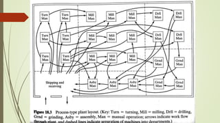
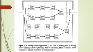
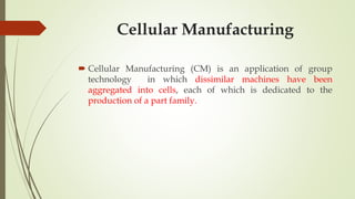
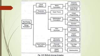
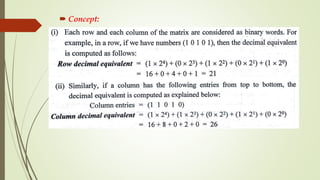
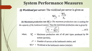
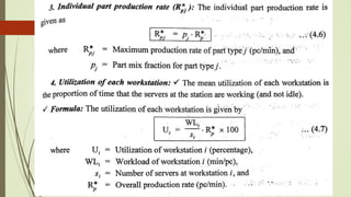
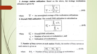
SlideShare a Scribd company logo
1 of 183
UNIT 3
CELLULAR MANUFACTURING
 Group Technology(GT), Part Families – Parts Classification and
coding – Simple Problems in Opitz Part Coding system –
Production flow Analysis – Cellular Manufacturing – Composite
part concept – Machine cell design and layout – Quantitative
analysis in Cellular Manufacturing – Rank Order Clustering Method
- Arranging Machines in a GT cell – Hollier Method – Simple
Problems.
GROUP TECHNOLOGY
❧It’s the manufacturing philosophy to increase the
production efficiency by grouping a variety of parts
having similarities of shape, dimension, and/or
process route.
❧It justifies batch production by capitalizing on design
and/or manufacturing similarities among
components parts.
Role of GT in
CAD/CAM
❧ For closer dimensional tolerances
❧ More economical in higher accuracy
❧ Increased variety of materials , by manufacturing needs.
❧ Lowering scrap rates
Important Elements of
CAD/CAM Integration
❧ It provides a common data base for effective integration of
CAD & CAM for successful implementation of CIM
❧ GT provides a common language for users
❧ It gives a information about Design, Manufacturing
Attributes, Processes & Capabilities
Part Families
❧ A part family is a collection of parts which are similar in
geometric shape and size or processing steps are required in
their manufacture.
❧ It may be a similar in their Design, Manufacturing
characteristics are grouped and referred as Design part
family & Manufacturing part family
❧ The characteristics used are known as Attributes
Similar manufacturing
process
METHODS FOR PART
FAMILY FORMATION
1.Visual inspection
2. part classification & Coding Methods
3.production flow analysis
1.Visual inspection
❧This is a simplest & least expensive
method
❧Here all are arranged in a similar groups
Visual Inspection
Method
2. Part classification &
Coding Methods
❧ Coding is systematic process by establishing an alpha-
numeric value for parts based on selected part features.
❧ Classification is the grouping of parts based on code values.
❧ Here parts are identified , listed and assigned as per the code
numbers both in Designing & Manufacturing.
Design & Manufacturing
Attributes
1.System based on Part Design Attributes
2.System based on Manufacturing Attributes
3.System based on Both Design & Manufacturing
Attributes
Coding System
Structure
❧A Group Technology is a string of
characteristics capturing information's about
an item.
❧A part coding scheme consists of a sequence
of symbols that identify the part’s Design /
Manufacturing attributes
Types of Basic Code
Structures
❧1. Hierarchical codes
(Mono codes or tree structure)
❧2. Attributes codes
(Poly code or chain type structure)
❧3. Decision tree codes
(hybrid code or mixed codes)
Hierarchical codes
❧The interpretation of each successive symbols
depends on the value of the preceding symbols
❧Each symbols amplifies the information contained in
the preceding digit, so that the digits in the symbols
cannot be interrupt alone.
❧The structure is like a tree.
Attribute Code
❧The interpretation of each symbols in the
sequence does not depend on the value of
preceding symbols.
❧Here each digit in this code represents
information in its own right and does not
directly qualify the information provided by
the other digits.
Decision-Tree Code
❧A hybrid code captures the best features of the
hierarchical & poly code Structures.
❧This system is also known as decision-tree coding
❧In this both the attributes are combined.
❧This is the mostly commonly used coding systems
with combined hybrid constructions.
Reason for using
Coding Scheme
❧ Design Retrievals
❧ Automated Process Planning
❧ Machine Cell Design
Coding Systems
 Through more than 100 coding systems are available, the
following coding systems are widely recognized in industries:
Opitz Classification Systems
❧ The opitz system was developed by H.Optiz of the university of
Aachen in Germany.
❧ It was the most popular and one of the first published
classification and coding scheme for mechanical parts
❧ This system uses alpha numeric symbols to represent the various
attributes of a part.
❧ The following digits sequence are:
❧ FORM CODE (12345) :This code is for
design attributes
❧ SUPPLEMENTARY CODE (6789): This
code is for Manufacturing related attributes
❧ SECONDARY CODE (ABCD): This code is
for production operation and sequence.
The MICLASS System
 MICLASS stands for Metal Institute Classification System.
This system was developed by Netherlands organization for
Applied Scientific research.
 MICLASS system is also referred as Multiclass system.
 The MICLASS classification number can range from 12 to 30
digits. The first 12 digits are universal codes that can be
applied to any part. The next 18 digits are called
supplementary digits.
DCLASS Coding System
 DCLASS stands for Design and Classification Information
system. It was developed at Brigham young university.
 The DCLASS part family code is comprised of eight digits
partitioned into five code segments, as shown in figure.
The KK-3 system
 The KK-3 system is a general purpose classification and
coding system for parts that are to be machined or ground.
 It is developed by the Japan Society for the Promotion of
Machine Industry in the late 1970s.
 It uses a 21 digit decimal system. The structure of a KK-3
system for rotational components is shown in figure
The CODE system
 The CODE system was developed by manufacturing data
system.
 The code number has eight digits. For each digit there are 16
possible values (0 to 9 and A to F) which are used to describe
the parts design and manufacturing characteristics.
 It is the method for identifying part families and associated
machine groupings that uses the information contained on
production route sheets rather on part drawings.
 In PFA, work parts with identical or similar routing are
classified into part families.
PRODUCTION FLOW
ANALYSIS
Data collection
Sorting of process routings
Preparation of PFA chart
Cluster analysis
Steps involved in PFA
Data Collection
 The step in the PFA procedure is to collect the necessary data.
 The route sheets of all components to be manufactured in the
shop are prepared. The route sheet should contain the part
number and operation sequence.
Sorting of process routings
 The second step in the PFA is to arrange the parts into groups
according to the similarity of their process routings.
 A typical card format is required for organising the data such
as the part number, sequence of code, and lot size.
Machines
Parts
P1 P2 P3 P4 P5 P6 P7 P8 P9
M1 1 1 1 1
M2 1 1
M3 1 1 1
M4 1 1 1
M5 1 1
M6 1 1
M7 1 1 1
PFA CHART
Re Arranged PFA Chart
Machines
Parts
P1 P8 P2 P4 P6 P7 P9 P3 P5
M1 1 1 1 1
M5 1 1
M4 1 1 1
M7 1 1 1
M3 1 1 1
M6 1 1
M2 1 1
Re Arranged PFA Chart
Part Families
 PF1 = P1,P8
 PF2 = P2,P4,P6,P7
 PF3 = P3,P5,P9
Cell groups
 C1 = M1,M5
 C2 = M4,M7
 C3 = M2,M3,M6
Facility Design Using Group
Technology
Line layout
Functional layout
Group layout
3 basic ways to arrange machines in
a shop
Cellular Manufacturing
 Cellular Manufacturing (CM) is an application of group
technology in which dissimilar machines have been
aggregated into cells, each of which is dedicated to the
production of a part family.
 A composite part is the hypothetical part which includes all of the
design and manufacturing attributes of a family.
 The composite is a single hypothetical part that can be completely
processed in a manufacturing cell.
 If a new part is loaded in a machine group and if the degree of
dis-similarity of the part from the hypothetical composite part is
minimum, then the new part can be processed in the same
manufacturing cell.
Composite Part Concept
 It simplifies the identification of groups
 It provides a basis for the design of group tooling.
 It helps to develop the optimized process plan for the parts
Uses of composite concept
Machine cell design
 The important aspect of cellular manufacturing is the design
of the machine cell, because the cell design influences
significantly the performance of the cell.
Types of Machine cells and
Layouts
 Based on the number of machines used and the degree of
mechanisation of material handling involved, the manufacturing cells
can be classified into the following four categories.
Single machine cell
Group machine cells with manual handling
Group machine cell with semi integrated handling
Flexible manufacturing cell or flexible manufacturing system
Single machine cell
 The single machine cell consists of one machine with
supporting fixtures and tooling organized to produce one or
more part families.
Group machine cells with manual
handling
 A group machine cell with material handling is an
arrangement of more than one machine employed to produce
one or more part families.
 The human operator performs the material handling.
Group machine cell with semi
integrated handling
 A mechanised handling system is used in group machine cell
with semi-integrated handling.
 In this type of cell design, mechanised conveyors are
generally used to move components between machines.
 For a group machine with semi integrated handling, any of
the following three machine layouts can be used
In line layout
Loop layout
Rectangular layout
Flexible manufacturing cell or
flexible manufacturing system
 FMS employs a fully integrated handling system with
automated processing stations.
 Out of all four types of machine cells, the FMS is the highly
automated GT machine cell.
Types of Part movements Vs
Machine Layout Types
Factors Influencing Cell Layout
 The various factors to be considered during the cell design
includes
Production rate
Number of parts/year
Processing time/part at each station
Type of part
Part Size, Shape and Weight
Routing of the parts.
Key Machine Concept
 In a GT machine cell, a certain machine is referred as the key
machine or bottleneck machine:
i) when that machine is more expensive to operate than the
other machines in the cell
ii) when that machine performs certain critical operations in the
shop floor.
 The other machines (expect Key machine) in the cell are
referred to as supporting machines.
Quantitative Analysis in Cellular
Manufacturing
 The various quantitative techniques that are developed for
cellular manufacturing system address the following two
problem areas:
 Grouping parts and machines into families
 Arranging machines in a GT cell
Grouping parts and machines
into families
 The basic objectives are
Identification of part families
Identification of machine cells
Rank Order Clustering (ROC)
Algorithm
 It is also known as Binary Ordering Algorithm (BOA).
 Input: Part-Machine incidence matrix.
 Concept:
Steps in ROC Algorithm
 Step 0: Input: Total number of parts, part routing (Part sequences)
 Step 1 : i) For each row, assign binary weights and calculate decimal
equivalents.
ii) Rank the rows in order of decreasing value. That is, the rows with the
highest decimal equivalent is considered to have the highest rank 1 among
the rows and so on.
 Step 2: Numbering from top to bottom, check whether the current order
of rows is the same as the rank order obtained in the previous step? If not,
go to step 3 ; if yes, go to step 7.
Step 3: Rearrange the rows of the matrix rank wise (High to Low from
top to bottom)
 Step 4 : for each column, assign binary weights and calculate
decimal equivalents.
Rank the columns in order to decreasing value. That is, the
column with the highest decimal equivalent is considered to
have the highest rank among the columns and so on.
 Step 5 : Numbering from left to right. Check whether the
current order of columns is the same as the rank order
obtained in the previous step? If not, go to the step 6; If yes,
go to step 7.
 Step 6: Rearrange the columns of the matrix rank wise
 Step 7: the final part machine incidence matrix. Stop and
print
Example: Apply Rank ordering clustering technique to the part-machine
incidence matrix shown in Table to arrange parts and machines into groups.
Table: Initial part machine incidence matrix
Arranging Machines in a GT Cell
 After part-machine groupings have been identified (By Rank
Order Clustering Algorithm), the next problem is to arrange
the machines into the most logical sequence.
 Having identified machine cells already, the next issues in the
design of cellular manufacturing system are:
 The determination of the most logical machine sequence in each cell
 The development of a feasible layout plan for each cell
Hollier Method
 Hollier method 1 requires many iterations to obtain the
machine sequence.
 Hollier method 2 provides the most logical machine sequence
in a GT cell in a single iteration.
Hollier method 2 Procedure
 Step 1 : Develop the from To Chart from part routing data
 Step 2 : Calculate the “From/To ratio” for each machine
 Step 3 : Arrange Machines in a GT Cell in order of decreasing
“From/To ratio”
Step 1 : Develop the from To
Chart from part routing data
 The From To chart provides information concerning the
number of part moves between the machines/workstations in
the cell.
 The From To chart is usually developed from the part routing
data.
 It should be noted that the part moves into and out of the cell
are not included in the From To chart.
Step 2 : Calculate the “From/To
ratio” for each machine
 Firstly, determine the “From” sum and “To” sum for each
machine.
 Now, calculate the “From/To ratio” for each machine by
dividing the “From” sum for each machine by the respective
“To” sum.
Step 3 : Arrange Machines in a
GT Cell in order of decreasing
“From/To ratio”
 Arrange machines in order of decreasing “From/To ratio”.
 Machines are arranged in the order given below:
Machines with high “From/To ratio” are placed at the
beginning of the work flow.
Machines with low “From/To ratio” are placed at the end of the
work flow.
Tie breaker: If a tie occurs, the machine with the higher “From”
sum is placed first.
Performance Measures for
Machine Sequences in a GT Cell
 Percentage of In sequence moves
 Percentage of Bypassing moves
 Percentage of Backtracking moves
Percentage of In sequence moves
Percentage of Bypassing moves
Percentage of Backtracking moves
FLEXIBLE MANUFACTURING SYSTEM
(FMS)
 Types of Flexibility - FMS – FMS Components – FMS Application
& Benefits – FMS Planning and Control– Quantitative analysis in
FMS – Simple Problems. Automated Guided Vehicle System
(AGVS) – AGVS Application – Vehicle Guidance technology –
Vehicle Management & Safety.
FMS
 FMS may be defined as “a highly automated GT machine cell,
consisting of a group of processing workstations (usually CNC
machine tools), interconnected by an automated material
handling and storage system, and controlled by a distributed
computer system.”
 FMS employs a fully integrated handling system with automated
processing stations.
Flexibility and its Types
 Flexibility is an attribute that allows a manufacturing system to
cope up with a certain level of variations in part or product type,
without having any interruption in production due to
changeovers between models.
 Flexibility measures the ability to adopt “to a wide range of
possible environment”
Tests of Flexibility
 Part variety test
 Schedule change test
 Error recovery test
 New part test
Types of Flexibility
 Machine flexibility
 Production flexibility
 Mix (or Process) flexibility
 Product flexibility
 Routing flexibility
 Volume (or capacity) flexibility
 Expansion flexibility
Machine flexibility
 Definition: Machine flexibility is the capability to adapt a given
machine in the system to a wide range of production operations
and part types.
 Influencing factors:
Setup or change over time
Ease with which part-programs can be downloaded to machines
Tool storage capacity of machine
Skill and versatility of workers in the systems
Production flexibility
 Definition: Production flexibility is the range of part types that
can be produced by a manufacturing system.
 Influencing factors:
Machine flexibility of individual stations
Range of machine flexibilities of all stations in the system
Mix (or Process) flexibility
 Definition: Mix flexibility, also known as process flexibility, is
the ability to change the product mix while maintaining the
same production quantity. i.e., producing the same parts only in
different proportions
 Influencing factors:
Similarity of parts in the mix
Machine flexibility
Relative work content times of parts produced
Product flexibility
 Definition: Product flexibility is the ability to change over to a
new set of products economically and quickly in response to the
changing market requirements.
 Influencing factors:
Relatedness of new part design with the existing part family
Off-line part program preparation
Machine flexibility
Routing flexibility
 Definition: Routing flexibility is the capacity to produce parts on
alternative workstation in case of equipment breakdowns, tool
failure, and other interruptions at any particular station.
 Influencing factors:
Similarity of parts in the mix
Similarity of workstations
Common testing
Volume (or capacity) flexibility
 Definition: Volume flexibility, also known as capacity flexibility,
is the ability of the system to vary the production volumes of
different products to accommodate changes in demand while
remaining profitable.
 Influencing factors:
Level of manual labour performing production
Amount invested in capital equipment
Expansion flexibility
 Definition: Expansion flexibility is the ease with which the
system can be expanded to foster total production volume.
 Influencing factors:
Cost incurred in adding new workstations and trained workers
Easiness in expansion of layout
Type of part handling system
Four Tests of Flexibility Vs Seven Types of Flexibility
Sl No Flexibility Test Type of Flexibility
1 Part Variety  Machine
 Production
2 Schedule Change  Mix
 Volume
 Expansion
3 Error recovery  Routing
4 New part  Product
Types of FMS
 Classification based on the kinds of operations they perform
Processing operation
Assembly operation
 Classification based on the number of machines in the system
Single machine cell (SMC)
Flexible machine cell (FMC)
Flexible manufacturing system (FMS)
 Classification based on the level of flexibility associated with the system
Dedicated FMS
Random order FMS
Classification based on the kinds of
operations they perform
 Processing operation
Processing operation transforms a work material from one state to another
moving towards the final desired part or product.
It adds value by changing the geometry, properties or appearance of the
starting materials.
 Assembly operation
Assembly operation involves joining of two or more components to create a
new entity which is called an assembly.
Permanent joining processes include welding, brazing, soldering, adhesive
banding, rivets, press fitting and expansion fits.
Classification based on the number
of machines in the system
 Single Machine Cell (SMC)
Flexible machine cell (FMC)
Flexible manufacturing system (FMS)
Summary
Classification based on the level of
flexibility associated with the system
Dedicated FMS
A dedicated FMS is designed to produce a limited variety of part
configurations.
Thus the dedicated FMS usually consists of special purpose machines
rather than general purpose machines.
Random order FMS
The random order FMS is equipped with general purpose machines so as
to meet the product variations. Also FMS type requires a more
sophisticated computer control system.
Components/Elements of FMS
 Workstations
 Material handling and storage system
 Computer control system
 Human resources
FMS Workstations
 The workstations/processing stations used in FMS depends upon the
type of product manufactured by the system.
 The types of workstations that are usually found in a FMS are:
Load/unload stations
Machining stations
Assembly workstations
Inspection station
Other processing stations
Material handling and storage system
 FMS material handling and storage system include part
transportation, raw material and final product transportation
and storage of workpieces, empty pallets, auxiliary materials,
wastes, fixtures and tools.
 Functions of the material handling system
 Types of FMS layout
 Types of handling equipment used in FMS
Functions of the material handling
system
 Material handling may be defined as the functions and systems
associated with the transportation, storage, and physical control
to work-in-process material in manufacturing.
 The general purpose of material handling in a factory is to move
raw materials, work-in-process, finished parts, tools, and
supplies from one location to another to facilitate the overall
operations of manufacturing.
Types of FMS layout Configurations
 In-line layout
 Loop layout
 Ladder layout
 Open-field layout
 Robot-centered cell
In-line layout
 As the name suggests, the materials and handling systems are
arranged in a straight line in the in-line layout.
Loop layout
 In the loop layout, the workstations are arranged in a loop, as
shown in figure.
Ladder layout
 The ladder layout, an adaptation of the loop layout, consists of a
loop with rungs on which workstations are located.
Open-field layout
 The open field layout, also an adaptation of the loop
configuration, consists of multiple loops, ladders and sliding
organized to achieve the desired processing requirements.
Robot-centered cell
 In the robot-centered cell, one or more robots are used as the
material handling system.
Types of handling equipment used in
FMS
 Primary Handling System
 Secondary Handling System
Primary Handling System
 The primary handling system establishes the basic layout of the
FMS and is responsible for moving work parts between work
stations in the system.
Secondary Handling System
 The secondary handling system consists of transfer devices,
automatic pallet changers, and similar mechanisms located at
the workstations in the FMS.
 The functions of the secondary handling systems are:
To transfer work parts from the primary system to the machine
tool or other processing stations.
To position the work parts with sufficient accuracy and
repeatability at the workstation for processing.
To provide buffer storage of work parts at each workstation.
Types of Material Handling
Equipment
 The material handling equipment commonly used to move parts
between stations can be grouped under six categories,
 Conveyors
 Cranes and hoists
 Industrial trucks
 Monorails and other rail guided vehicles
 Automated guided vehicles (AGVs) and
 Industrial robots.
Computer control system
 In flexible manufacturing systems, computers are required to
control the automated and semi-automated equipment and to
participate in the over all coordination and management of the
manufacturing system.
 A typical FMS computer control system consists of a central
computer and micro computers controlling the individual
machines and other components.
Functions of a FMS computer control
system
 Workstation/processing station control
 Distribution of control instructions to workstations
 Production control
 Material handling system control
 Workpiece monitoring
 Tool control
 Quality control
 Failure diagnosis
 Safety monitoring
 Performance monitoring and reporting
Structure of FMS Application software systems
Types of FMS Data Files
 Part program file
 Routing file
 Part production file
 Pallet reference file
 Station tool file
 Tool life file
Human Resources
 In FMS, human labours are needed to perform the following functions
To load raw work parts into the system
To unload finished work parts from the system
For tool changing and tool setting
For equipment maintenance and repair
To program and operate the computer system
To accomplish overall management of the system
Example of Flexible
Manufacturing System
 FMS installed at Vought Aerospace in Dallas
FMS Applications
 Machining
 Assembly
 Sheet-metal press working
 Forging
 Plastic injection moulding
 Welding
 Textile machinery manufacture
 Semiconductor component manufacture
Economics of FMS
 5-20% reduction in personnel
 15-30% reduction in engineering design cost
 30-60% reduction in overall lead time
 30-60% reduction in work-in-process
 40-70% gain in overall production
 200-300% gain in capital equipment operating time
 200-500% gain in product quality
 300-500% gain in engineering productivity
Advantages of FMS
(Benefits of FMS)
 Increased machine utilization
 Reduced inventory
 Reduced manufacturing lead time
 Greater flexibility in production scheduling
 Reduced direct labour cost
 Increased labour productivity
 Shorter response time
 Consistent quality
 Reduced factory floor space
 Reduced number of tools and machines required
 Improved product quality
Disadvantages of FMS
 Very high capital investment is required to implement a FMS
 Acquiring, training and maintaining the knowledgeable labour
pool requires heavy investment
 Fixtures can sometimes cost much more with FMS, and software
development costs could be as much as 12-20% of the total
expense
 Tool performance and condition monitoring can also be
expensive since tool variety could undermine efficiency
 Complex design estimating methodology requires optimizing
the degree of flexibility and finding a trade off between
flexibility and specialization
FMS Planning and Control
(FMS Planning and Implementation
issues)
 FMS planning and design issues
 FMS control (or operational) issues
FMS Planning issues
 Part family considerations
 Processing requirements
 Physical characteristics of the work parts
 Production volume
FMS design issues
 Type of work stations
 Variations in process routings and FMS layout
 Material handling system
 Work-in-process and storage capacity
 Tooling
 Pallet fixtures
FMS operational issues
 Scheduling and dispatching
 Machine loading
 Part routing
 Part grouping
 Tool management
 Pallet and fixture allocation
Quantitative analysis of Flexible
Manufacturing System
 Flexible manufacturing system can be analysed using different
models. The four different categories of FMS analysis models
are:
Deterministic models
Queuing models
Discrete event simulation
Other techniques
Bottleneck model
 The bottleneck model is a simple and intuitive approach to
determine the starting estimates of FMS design parameters such
as production rate, capacity and utilization.
Terminology and symbols
FMS operational Parameters
System Performance Measures
Unit 5 -cellular manufacturing & fms

More Related Content

What's hot

06 group technology
06 group technology06 group technology
06 group technologyArif Rahman
 
Computer Integrated Manufacturing System
Computer Integrated Manufacturing SystemComputer Integrated Manufacturing System
Computer Integrated Manufacturing SystemSaif Eye
 
CAD/CAM/CIM (18ME72) Module -4 Part-A
CAD/CAM/CIM (18ME72) Module -4 Part-ACAD/CAM/CIM (18ME72) Module -4 Part-A
CAD/CAM/CIM (18ME72) Module -4 Part-AMohammed Imran
 
Group technology, Production flow Analysis
Group technology, Production flow AnalysisGroup technology, Production flow Analysis
Group technology, Production flow AnalysisKEERTHIVASAN RAVI
 
Cellular manufacturing and group technology
Cellular manufacturing and group technologyCellular manufacturing and group technology
Cellular manufacturing and group technologyHitendrasinh Zala
 
Interpolation
InterpolationInterpolation
Interpolationmbhuiya6
 
Unit iv Shop floor control and FMS
Unit iv Shop floor control and FMSUnit iv Shop floor control and FMS
Unit iv Shop floor control and FMSmanimaran m
 
Flexible manufacturing systems (FMS)
Flexible manufacturing systems (FMS)Flexible manufacturing systems (FMS)
Flexible manufacturing systems (FMS)jntuhcej
 
Introduction to Group technology
Introduction to Group technologyIntroduction to Group technology
Introduction to Group technologyHashim Hasnain Hadi
 
Group Technology, coding and cell design
Group Technology, coding and cell designGroup Technology, coding and cell design
Group Technology, coding and cell designNauman khan
 
GROUP TECHNOLOGY AND CAPP
GROUP TECHNOLOGY AND CAPPGROUP TECHNOLOGY AND CAPP
GROUP TECHNOLOGY AND CAPPmanimaran m
 
COMPUTER AIDED PROCESS PLANNING (CAPP)
COMPUTER AIDED PROCESS PLANNING (CAPP)COMPUTER AIDED PROCESS PLANNING (CAPP)
COMPUTER AIDED PROCESS PLANNING (CAPP)Victor Al
 
Tool changing mechanism in cnc machine
Tool changing mechanism in cnc machineTool changing mechanism in cnc machine
Tool changing mechanism in cnc machineBhaveshChaudhari21
 
Uint 1 locating and clamping devices
Uint 1 locating and clamping devicesUint 1 locating and clamping devices
Uint 1 locating and clamping devicesS.DHARANI KUMAR
 
ANALYSIS OF TRANSFER LINE WITH BUFFER STORAGE
ANALYSIS OF TRANSFER LINE WITH BUFFER STORAGEANALYSIS OF TRANSFER LINE WITH BUFFER STORAGE
ANALYSIS OF TRANSFER LINE WITH BUFFER STORAGEManoj Gowda K
 

What's hot (20)

06 group technology
06 group technology06 group technology
06 group technology
 
Computer Integrated Manufacturing System
Computer Integrated Manufacturing SystemComputer Integrated Manufacturing System
Computer Integrated Manufacturing System
 
CAD/CAM/CIM (18ME72) Module -4 Part-A
CAD/CAM/CIM (18ME72) Module -4 Part-ACAD/CAM/CIM (18ME72) Module -4 Part-A
CAD/CAM/CIM (18ME72) Module -4 Part-A
 
Group technology, Production flow Analysis
Group technology, Production flow AnalysisGroup technology, Production flow Analysis
Group technology, Production flow Analysis
 
Cellular manufacturing and group technology
Cellular manufacturing and group technologyCellular manufacturing and group technology
Cellular manufacturing and group technology
 
Tool presetting
Tool presettingTool presetting
Tool presetting
 
Interpolation
InterpolationInterpolation
Interpolation
 
Unit iv Shop floor control and FMS
Unit iv Shop floor control and FMSUnit iv Shop floor control and FMS
Unit iv Shop floor control and FMS
 
Group Technology
Group TechnologyGroup Technology
Group Technology
 
Flexible manufacturing systems (FMS)
Flexible manufacturing systems (FMS)Flexible manufacturing systems (FMS)
Flexible manufacturing systems (FMS)
 
Introduction to Group technology
Introduction to Group technologyIntroduction to Group technology
Introduction to Group technology
 
Assembly modelling
Assembly modellingAssembly modelling
Assembly modelling
 
Group Technology, coding and cell design
Group Technology, coding and cell designGroup Technology, coding and cell design
Group Technology, coding and cell design
 
GROUP TECHNOLOGY AND CAPP
GROUP TECHNOLOGY AND CAPPGROUP TECHNOLOGY AND CAPP
GROUP TECHNOLOGY AND CAPP
 
Group technology and cellular manufacturing
Group technology and cellular manufacturingGroup technology and cellular manufacturing
Group technology and cellular manufacturing
 
COMPUTER AIDED PROCESS PLANNING (CAPP)
COMPUTER AIDED PROCESS PLANNING (CAPP)COMPUTER AIDED PROCESS PLANNING (CAPP)
COMPUTER AIDED PROCESS PLANNING (CAPP)
 
Group Technology
Group TechnologyGroup Technology
Group Technology
 
Tool changing mechanism in cnc machine
Tool changing mechanism in cnc machineTool changing mechanism in cnc machine
Tool changing mechanism in cnc machine
 
Uint 1 locating and clamping devices
Uint 1 locating and clamping devicesUint 1 locating and clamping devices
Uint 1 locating and clamping devices
 
ANALYSIS OF TRANSFER LINE WITH BUFFER STORAGE
ANALYSIS OF TRANSFER LINE WITH BUFFER STORAGEANALYSIS OF TRANSFER LINE WITH BUFFER STORAGE
ANALYSIS OF TRANSFER LINE WITH BUFFER STORAGE
 

Similar to Unit 5 -cellular manufacturing & fms

Unit 5 -1-ME8691 & COMPUTER AIDED DESIGN AND MANUFACTURING
Unit 5 -1-ME8691 & COMPUTER AIDED DESIGN AND    MANUFACTURINGUnit 5 -1-ME8691 & COMPUTER AIDED DESIGN AND    MANUFACTURING
Unit 5 -1-ME8691 & COMPUTER AIDED DESIGN AND MANUFACTURINGMohanumar S
 
Unit 5-CELLULAR MANUFACTURING AND FLEXIBLE MANUFACTURING SYSTEM (FMS) .pptx
Unit 5-CELLULAR MANUFACTURING AND FLEXIBLE MANUFACTURING SYSTEM (FMS) .pptxUnit 5-CELLULAR MANUFACTURING AND FLEXIBLE MANUFACTURING SYSTEM (FMS) .pptx
Unit 5-CELLULAR MANUFACTURING AND FLEXIBLE MANUFACTURING SYSTEM (FMS) .pptxdinesh babu
 
CAD LECTURE 2.pptx
CAD LECTURE 2.pptxCAD LECTURE 2.pptx
CAD LECTURE 2.pptxAbhiKarn2
 
UNIT -3-02225265555- CELLULA MANUFACTURING .ppt
UNIT -3-02225265555- CELLULA MANUFACTURING .pptUNIT -3-02225265555- CELLULA MANUFACTURING .ppt
UNIT -3-02225265555- CELLULA MANUFACTURING .pptdharma raja`
 
group technology-and-cellular-manufacturing-i
 group technology-and-cellular-manufacturing-i group technology-and-cellular-manufacturing-i
group technology-and-cellular-manufacturing-iAshok Mannava
 
Lec2 GT.pptx. grouptechnology definition and application
Lec2 GT.pptx. grouptechnology definition and applicationLec2 GT.pptx. grouptechnology definition and application
Lec2 GT.pptx. grouptechnology definition and applicationssuserac3f5b
 
Group technology (GT).pdf .
Group technology (GT).pdf                      .Group technology (GT).pdf                      .
Group technology (GT).pdf .Athar739197
 
Cad lecture-5
Cad lecture-5Cad lecture-5
Cad lecture-527273737
 
cellular manufacturing for production system
cellular manufacturing for production systemcellular manufacturing for production system
cellular manufacturing for production systemRAJESHS631800
 
Group technology ppt @ bec doms
Group technology ppt @ bec domsGroup technology ppt @ bec doms
Group technology ppt @ bec domsBabasab Patil
 
Computer control in process planning Unit 4 (ME CAD/CAM)
Computer control in process planning Unit 4 (ME CAD/CAM)Computer control in process planning Unit 4 (ME CAD/CAM)
Computer control in process planning Unit 4 (ME CAD/CAM)Avt Shubhash
 
Group Technology
Group TechnologyGroup Technology
Group TechnologyAamir Ali
 

Similar to Unit 5 -cellular manufacturing & fms (20)

Unit 5 -1-ME8691 & COMPUTER AIDED DESIGN AND MANUFACTURING
Unit 5 -1-ME8691 & COMPUTER AIDED DESIGN AND    MANUFACTURINGUnit 5 -1-ME8691 & COMPUTER AIDED DESIGN AND    MANUFACTURING
Unit 5 -1-ME8691 & COMPUTER AIDED DESIGN AND MANUFACTURING
 
Unit 5-CELLULAR MANUFACTURING AND FLEXIBLE MANUFACTURING SYSTEM (FMS) .pptx
Unit 5-CELLULAR MANUFACTURING AND FLEXIBLE MANUFACTURING SYSTEM (FMS) .pptxUnit 5-CELLULAR MANUFACTURING AND FLEXIBLE MANUFACTURING SYSTEM (FMS) .pptx
Unit 5-CELLULAR MANUFACTURING AND FLEXIBLE MANUFACTURING SYSTEM (FMS) .pptx
 
CAD LECTURE 2.pptx
CAD LECTURE 2.pptxCAD LECTURE 2.pptx
CAD LECTURE 2.pptx
 
Unit 3 cim
Unit 3  cimUnit 3  cim
Unit 3 cim
 
UNIT -3-02225265555- CELLULA MANUFACTURING .ppt
UNIT -3-02225265555- CELLULA MANUFACTURING .pptUNIT -3-02225265555- CELLULA MANUFACTURING .ppt
UNIT -3-02225265555- CELLULA MANUFACTURING .ppt
 
group technology-and-cellular-manufacturing-i
 group technology-and-cellular-manufacturing-i group technology-and-cellular-manufacturing-i
group technology-and-cellular-manufacturing-i
 
Group technology
Group technologyGroup technology
Group technology
 
Lec2 GT.pptx. grouptechnology definition and application
Lec2 GT.pptx. grouptechnology definition and applicationLec2 GT.pptx. grouptechnology definition and application
Lec2 GT.pptx. grouptechnology definition and application
 
Group technology (GT).pdf .
Group technology (GT).pdf                      .Group technology (GT).pdf                      .
Group technology (GT).pdf .
 
Cad lecture-5
Cad lecture-5Cad lecture-5
Cad lecture-5
 
Cim ppt
Cim pptCim ppt
Cim ppt
 
cellular manufacturing for production system
cellular manufacturing for production systemcellular manufacturing for production system
cellular manufacturing for production system
 
Cellular manufacturing
Cellular manufacturingCellular manufacturing
Cellular manufacturing
 
Group technology ppt @ bec doms
Group technology ppt @ bec domsGroup technology ppt @ bec doms
Group technology ppt @ bec doms
 
Computer control in process planning Unit 4 (ME CAD/CAM)
Computer control in process planning Unit 4 (ME CAD/CAM)Computer control in process planning Unit 4 (ME CAD/CAM)
Computer control in process planning Unit 4 (ME CAD/CAM)
 
Group technology .pptx
Group technology .pptxGroup technology .pptx
Group technology .pptx
 
CIM MODULE 2.pptx
CIM MODULE 2.pptxCIM MODULE 2.pptx
CIM MODULE 2.pptx
 
Me6703 cim systems
Me6703 cim systemsMe6703 cim systems
Me6703 cim systems
 
group technology
group technologygroup technology
group technology
 
Group Technology
Group TechnologyGroup Technology
Group Technology
 

More from ravis205084

UNIT V ACTUATORS AND MECHATRONIC SYSTEM DESIGN
UNIT V ACTUATORS AND MECHATRONIC SYSTEM DESIGN UNIT V ACTUATORS AND MECHATRONIC SYSTEM DESIGN
UNIT V ACTUATORS AND MECHATRONIC SYSTEM DESIGN ravis205084
 
UNIT IV PROGRAMMABLE LOGIC CONTROLLER
UNIT IV PROGRAMMABLE LOGIC CONTROLLER UNIT IV PROGRAMMABLE LOGIC CONTROLLER
UNIT IV PROGRAMMABLE LOGIC CONTROLLER ravis205084
 
UNIT III PROGRAMMABLE PERIPHERAL INTERFACE
UNIT III PROGRAMMABLE PERIPHERAL INTERFACE UNIT III PROGRAMMABLE PERIPHERAL INTERFACE
UNIT III PROGRAMMABLE PERIPHERAL INTERFACE ravis205084
 
UNIT II MICROPROCESSOR AND MICROCONTROLLER
UNIT II MICROPROCESSOR AND MICROCONTROLLER UNIT II MICROPROCESSOR AND MICROCONTROLLER
UNIT II MICROPROCESSOR AND MICROCONTROLLER ravis205084
 
UNIT I INTRODUCTION (MECHATRONICS)
UNIT I INTRODUCTION (MECHATRONICS)UNIT I INTRODUCTION (MECHATRONICS)
UNIT I INTRODUCTION (MECHATRONICS)ravis205084
 
UNIT III CAD STANDARDS
UNIT III CAD STANDARDS UNIT III CAD STANDARDS
UNIT III CAD STANDARDS ravis205084
 
UNIT II GEOMETRIC MODELING (COMPUTER AIDED DESIGN AND MANUFACTURING )
UNIT II GEOMETRIC MODELING (COMPUTER AIDED DESIGN AND MANUFACTURING )UNIT II GEOMETRIC MODELING (COMPUTER AIDED DESIGN AND MANUFACTURING )
UNIT II GEOMETRIC MODELING (COMPUTER AIDED DESIGN AND MANUFACTURING )ravis205084
 
Unit 1 INTRODUCTION (COMPUTER AIDED DESIGN AND MANUFACTURING )
Unit 1 INTRODUCTION (COMPUTER AIDED DESIGN AND MANUFACTURING )Unit 1 INTRODUCTION (COMPUTER AIDED DESIGN AND MANUFACTURING )
Unit 1 INTRODUCTION (COMPUTER AIDED DESIGN AND MANUFACTURING )ravis205084
 

More from ravis205084 (13)

Unit - 1.pptx
Unit - 1.pptxUnit - 1.pptx
Unit - 1.pptx
 
unit-2.pptx
unit-2.pptxunit-2.pptx
unit-2.pptx
 
unit-3.pdf
unit-3.pdfunit-3.pdf
unit-3.pdf
 
Unit-4.pdf
Unit-4.pdfUnit-4.pdf
Unit-4.pdf
 
UNIT-5.pptx
UNIT-5.pptxUNIT-5.pptx
UNIT-5.pptx
 
UNIT V ACTUATORS AND MECHATRONIC SYSTEM DESIGN
UNIT V ACTUATORS AND MECHATRONIC SYSTEM DESIGN UNIT V ACTUATORS AND MECHATRONIC SYSTEM DESIGN
UNIT V ACTUATORS AND MECHATRONIC SYSTEM DESIGN
 
UNIT IV PROGRAMMABLE LOGIC CONTROLLER
UNIT IV PROGRAMMABLE LOGIC CONTROLLER UNIT IV PROGRAMMABLE LOGIC CONTROLLER
UNIT IV PROGRAMMABLE LOGIC CONTROLLER
 
UNIT III PROGRAMMABLE PERIPHERAL INTERFACE
UNIT III PROGRAMMABLE PERIPHERAL INTERFACE UNIT III PROGRAMMABLE PERIPHERAL INTERFACE
UNIT III PROGRAMMABLE PERIPHERAL INTERFACE
 
UNIT II MICROPROCESSOR AND MICROCONTROLLER
UNIT II MICROPROCESSOR AND MICROCONTROLLER UNIT II MICROPROCESSOR AND MICROCONTROLLER
UNIT II MICROPROCESSOR AND MICROCONTROLLER
 
UNIT I INTRODUCTION (MECHATRONICS)
UNIT I INTRODUCTION (MECHATRONICS)UNIT I INTRODUCTION (MECHATRONICS)
UNIT I INTRODUCTION (MECHATRONICS)
 
UNIT III CAD STANDARDS
UNIT III CAD STANDARDS UNIT III CAD STANDARDS
UNIT III CAD STANDARDS
 
UNIT II GEOMETRIC MODELING (COMPUTER AIDED DESIGN AND MANUFACTURING )
UNIT II GEOMETRIC MODELING (COMPUTER AIDED DESIGN AND MANUFACTURING )UNIT II GEOMETRIC MODELING (COMPUTER AIDED DESIGN AND MANUFACTURING )
UNIT II GEOMETRIC MODELING (COMPUTER AIDED DESIGN AND MANUFACTURING )
 
Unit 1 INTRODUCTION (COMPUTER AIDED DESIGN AND MANUFACTURING )
Unit 1 INTRODUCTION (COMPUTER AIDED DESIGN AND MANUFACTURING )Unit 1 INTRODUCTION (COMPUTER AIDED DESIGN AND MANUFACTURING )
Unit 1 INTRODUCTION (COMPUTER AIDED DESIGN AND MANUFACTURING )
 

Recently uploaded

Coefficient of Thermal Expansion and their Importance.pptx
Coefficient of Thermal Expansion and their Importance.pptxCoefficient of Thermal Expansion and their Importance.pptx
Coefficient of Thermal Expansion and their Importance.pptxAsutosh Ranjan
 
Introduction to Multiple Access Protocol.pptx
Introduction to Multiple Access Protocol.pptxIntroduction to Multiple Access Protocol.pptx
Introduction to Multiple Access Protocol.pptxupamatechverse
 
Call for Papers - African Journal of Biological Sciences, E-ISSN: 2663-2187, ...
Call for Papers - African Journal of Biological Sciences, E-ISSN: 2663-2187, ...Call for Papers - African Journal of Biological Sciences, E-ISSN: 2663-2187, ...
Call for Papers - African Journal of Biological Sciences, E-ISSN: 2663-2187, ...Christo Ananth
 
Porous Ceramics seminar and technical writing
Porous Ceramics seminar and technical writingPorous Ceramics seminar and technical writing
Porous Ceramics seminar and technical writingrakeshbaidya232001
 
Software Development Life Cycle By Team Orange (Dept. of Pharmacy)
Software Development Life Cycle By  Team Orange (Dept. of Pharmacy)Software Development Life Cycle By  Team Orange (Dept. of Pharmacy)
Software Development Life Cycle By Team Orange (Dept. of Pharmacy)Suman Mia
 
Analog to Digital and Digital to Analog Converter
Analog to Digital and Digital to Analog ConverterAnalog to Digital and Digital to Analog Converter
Analog to Digital and Digital to Analog ConverterAbhinavSharma374939
 
Structural Analysis and Design of Foundations: A Comprehensive Handbook for S...
Structural Analysis and Design of Foundations: A Comprehensive Handbook for S...Structural Analysis and Design of Foundations: A Comprehensive Handbook for S...
Structural Analysis and Design of Foundations: A Comprehensive Handbook for S...Dr.Costas Sachpazis
 
The Most Attractive Pune Call Girls Budhwar Peth 8250192130 Will You Miss Thi...
The Most Attractive Pune Call Girls Budhwar Peth 8250192130 Will You Miss Thi...The Most Attractive Pune Call Girls Budhwar Peth 8250192130 Will You Miss Thi...
The Most Attractive Pune Call Girls Budhwar Peth 8250192130 Will You Miss Thi...ranjana rawat
 
(ANVI) Koregaon Park Call Girls Just Call 7001035870 [ Cash on Delivery ] Pun...
(ANVI) Koregaon Park Call Girls Just Call 7001035870 [ Cash on Delivery ] Pun...(ANVI) Koregaon Park Call Girls Just Call 7001035870 [ Cash on Delivery ] Pun...
(ANVI) Koregaon Park Call Girls Just Call 7001035870 [ Cash on Delivery ] Pun...ranjana rawat
 
Architect Hassan Khalil Portfolio for 2024
Architect Hassan Khalil Portfolio for 2024Architect Hassan Khalil Portfolio for 2024
Architect Hassan Khalil Portfolio for 2024hassan khalil
 
MANUFACTURING PROCESS-II UNIT-5 NC MACHINE TOOLS
MANUFACTURING PROCESS-II UNIT-5 NC MACHINE TOOLSMANUFACTURING PROCESS-II UNIT-5 NC MACHINE TOOLS
MANUFACTURING PROCESS-II UNIT-5 NC MACHINE TOOLSSIVASHANKAR N
 
SPICE PARK APR2024 ( 6,793 SPICE Models )
SPICE PARK APR2024 ( 6,793 SPICE Models )SPICE PARK APR2024 ( 6,793 SPICE Models )
SPICE PARK APR2024 ( 6,793 SPICE Models )Tsuyoshi Horigome
 
HARDNESS, FRACTURE TOUGHNESS AND STRENGTH OF CERAMICS
HARDNESS, FRACTURE TOUGHNESS AND STRENGTH OF CERAMICSHARDNESS, FRACTURE TOUGHNESS AND STRENGTH OF CERAMICS
HARDNESS, FRACTURE TOUGHNESS AND STRENGTH OF CERAMICSRajkumarAkumalla
 
High Profile Call Girls Nagpur Isha Call 7001035870 Meet With Nagpur Escorts
High Profile Call Girls Nagpur Isha Call 7001035870 Meet With Nagpur EscortsHigh Profile Call Girls Nagpur Isha Call 7001035870 Meet With Nagpur Escorts
High Profile Call Girls Nagpur Isha Call 7001035870 Meet With Nagpur Escortsranjana rawat
 
Processing & Properties of Floor and Wall Tiles.pptx
Processing & Properties of Floor and Wall Tiles.pptxProcessing & Properties of Floor and Wall Tiles.pptx
Processing & Properties of Floor and Wall Tiles.pptxpranjaldaimarysona
 
APPLICATIONS-AC/DC DRIVES-OPERATING CHARACTERISTICS
APPLICATIONS-AC/DC DRIVES-OPERATING CHARACTERISTICSAPPLICATIONS-AC/DC DRIVES-OPERATING CHARACTERISTICS
APPLICATIONS-AC/DC DRIVES-OPERATING CHARACTERISTICSKurinjimalarL3
 
(PRIYA) Rajgurunagar Call Girls Just Call 7001035870 [ Cash on Delivery ] Pun...
(PRIYA) Rajgurunagar Call Girls Just Call 7001035870 [ Cash on Delivery ] Pun...(PRIYA) Rajgurunagar Call Girls Just Call 7001035870 [ Cash on Delivery ] Pun...
(PRIYA) Rajgurunagar Call Girls Just Call 7001035870 [ Cash on Delivery ] Pun...ranjana rawat
 
the ladakh protest in leh ladakh 2024 sonam wangchuk.pptx
the ladakh protest in leh ladakh 2024 sonam wangchuk.pptxthe ladakh protest in leh ladakh 2024 sonam wangchuk.pptx
the ladakh protest in leh ladakh 2024 sonam wangchuk.pptxhumanexperienceaaa
 

Recently uploaded (20)

Coefficient of Thermal Expansion and their Importance.pptx
Coefficient of Thermal Expansion and their Importance.pptxCoefficient of Thermal Expansion and their Importance.pptx
Coefficient of Thermal Expansion and their Importance.pptx
 
Introduction to Multiple Access Protocol.pptx
Introduction to Multiple Access Protocol.pptxIntroduction to Multiple Access Protocol.pptx
Introduction to Multiple Access Protocol.pptx
 
DJARUM4D - SLOT GACOR ONLINE | SLOT DEMO ONLINE
DJARUM4D - SLOT GACOR ONLINE | SLOT DEMO ONLINEDJARUM4D - SLOT GACOR ONLINE | SLOT DEMO ONLINE
DJARUM4D - SLOT GACOR ONLINE | SLOT DEMO ONLINE
 
Call for Papers - African Journal of Biological Sciences, E-ISSN: 2663-2187, ...
Call for Papers - African Journal of Biological Sciences, E-ISSN: 2663-2187, ...Call for Papers - African Journal of Biological Sciences, E-ISSN: 2663-2187, ...
Call for Papers - African Journal of Biological Sciences, E-ISSN: 2663-2187, ...
 
Porous Ceramics seminar and technical writing
Porous Ceramics seminar and technical writingPorous Ceramics seminar and technical writing
Porous Ceramics seminar and technical writing
 
Software Development Life Cycle By Team Orange (Dept. of Pharmacy)
Software Development Life Cycle By  Team Orange (Dept. of Pharmacy)Software Development Life Cycle By  Team Orange (Dept. of Pharmacy)
Software Development Life Cycle By Team Orange (Dept. of Pharmacy)
 
9953056974 Call Girls In South Ex, Escorts (Delhi) NCR.pdf
9953056974 Call Girls In South Ex, Escorts (Delhi) NCR.pdf9953056974 Call Girls In South Ex, Escorts (Delhi) NCR.pdf
9953056974 Call Girls In South Ex, Escorts (Delhi) NCR.pdf
 
Analog to Digital and Digital to Analog Converter
Analog to Digital and Digital to Analog ConverterAnalog to Digital and Digital to Analog Converter
Analog to Digital and Digital to Analog Converter
 
Structural Analysis and Design of Foundations: A Comprehensive Handbook for S...
Structural Analysis and Design of Foundations: A Comprehensive Handbook for S...Structural Analysis and Design of Foundations: A Comprehensive Handbook for S...
Structural Analysis and Design of Foundations: A Comprehensive Handbook for S...
 
The Most Attractive Pune Call Girls Budhwar Peth 8250192130 Will You Miss Thi...
The Most Attractive Pune Call Girls Budhwar Peth 8250192130 Will You Miss Thi...The Most Attractive Pune Call Girls Budhwar Peth 8250192130 Will You Miss Thi...
The Most Attractive Pune Call Girls Budhwar Peth 8250192130 Will You Miss Thi...
 
(ANVI) Koregaon Park Call Girls Just Call 7001035870 [ Cash on Delivery ] Pun...
(ANVI) Koregaon Park Call Girls Just Call 7001035870 [ Cash on Delivery ] Pun...(ANVI) Koregaon Park Call Girls Just Call 7001035870 [ Cash on Delivery ] Pun...
(ANVI) Koregaon Park Call Girls Just Call 7001035870 [ Cash on Delivery ] Pun...
 
Architect Hassan Khalil Portfolio for 2024
Architect Hassan Khalil Portfolio for 2024Architect Hassan Khalil Portfolio for 2024
Architect Hassan Khalil Portfolio for 2024
 
MANUFACTURING PROCESS-II UNIT-5 NC MACHINE TOOLS
MANUFACTURING PROCESS-II UNIT-5 NC MACHINE TOOLSMANUFACTURING PROCESS-II UNIT-5 NC MACHINE TOOLS
MANUFACTURING PROCESS-II UNIT-5 NC MACHINE TOOLS
 
SPICE PARK APR2024 ( 6,793 SPICE Models )
SPICE PARK APR2024 ( 6,793 SPICE Models )SPICE PARK APR2024 ( 6,793 SPICE Models )
SPICE PARK APR2024 ( 6,793 SPICE Models )
 
HARDNESS, FRACTURE TOUGHNESS AND STRENGTH OF CERAMICS
HARDNESS, FRACTURE TOUGHNESS AND STRENGTH OF CERAMICSHARDNESS, FRACTURE TOUGHNESS AND STRENGTH OF CERAMICS
HARDNESS, FRACTURE TOUGHNESS AND STRENGTH OF CERAMICS
 
High Profile Call Girls Nagpur Isha Call 7001035870 Meet With Nagpur Escorts
High Profile Call Girls Nagpur Isha Call 7001035870 Meet With Nagpur EscortsHigh Profile Call Girls Nagpur Isha Call 7001035870 Meet With Nagpur Escorts
High Profile Call Girls Nagpur Isha Call 7001035870 Meet With Nagpur Escorts
 
Processing & Properties of Floor and Wall Tiles.pptx
Processing & Properties of Floor and Wall Tiles.pptxProcessing & Properties of Floor and Wall Tiles.pptx
Processing & Properties of Floor and Wall Tiles.pptx
 
APPLICATIONS-AC/DC DRIVES-OPERATING CHARACTERISTICS
APPLICATIONS-AC/DC DRIVES-OPERATING CHARACTERISTICSAPPLICATIONS-AC/DC DRIVES-OPERATING CHARACTERISTICS
APPLICATIONS-AC/DC DRIVES-OPERATING CHARACTERISTICS
 
(PRIYA) Rajgurunagar Call Girls Just Call 7001035870 [ Cash on Delivery ] Pun...
(PRIYA) Rajgurunagar Call Girls Just Call 7001035870 [ Cash on Delivery ] Pun...(PRIYA) Rajgurunagar Call Girls Just Call 7001035870 [ Cash on Delivery ] Pun...
(PRIYA) Rajgurunagar Call Girls Just Call 7001035870 [ Cash on Delivery ] Pun...
 
the ladakh protest in leh ladakh 2024 sonam wangchuk.pptx
the ladakh protest in leh ladakh 2024 sonam wangchuk.pptxthe ladakh protest in leh ladakh 2024 sonam wangchuk.pptx
the ladakh protest in leh ladakh 2024 sonam wangchuk.pptx
 

Unit 5 -cellular manufacturing & fms

  • 1. UNIT 3 CELLULAR MANUFACTURING  Group Technology(GT), Part Families – Parts Classification and coding – Simple Problems in Opitz Part Coding system – Production flow Analysis – Cellular Manufacturing – Composite part concept – Machine cell design and layout – Quantitative analysis in Cellular Manufacturing – Rank Order Clustering Method - Arranging Machines in a GT cell – Hollier Method – Simple Problems.
  • 2. GROUP TECHNOLOGY ❧It’s the manufacturing philosophy to increase the production efficiency by grouping a variety of parts having similarities of shape, dimension, and/or process route. ❧It justifies batch production by capitalizing on design and/or manufacturing similarities among components parts.
  • 3. Role of GT in CAD/CAM ❧ For closer dimensional tolerances ❧ More economical in higher accuracy ❧ Increased variety of materials , by manufacturing needs. ❧ Lowering scrap rates
  • 4. Important Elements of CAD/CAM Integration ❧ It provides a common data base for effective integration of CAD & CAM for successful implementation of CIM ❧ GT provides a common language for users ❧ It gives a information about Design, Manufacturing Attributes, Processes & Capabilities
  • 5.
  • 6. Part Families ❧ A part family is a collection of parts which are similar in geometric shape and size or processing steps are required in their manufacture. ❧ It may be a similar in their Design, Manufacturing characteristics are grouped and referred as Design part family & Manufacturing part family ❧ The characteristics used are known as Attributes
  • 7.
  • 8.
  • 10. METHODS FOR PART FAMILY FORMATION 1.Visual inspection 2. part classification & Coding Methods 3.production flow analysis
  • 11. 1.Visual inspection ❧This is a simplest & least expensive method ❧Here all are arranged in a similar groups
  • 13.
  • 14.
  • 15. 2. Part classification & Coding Methods ❧ Coding is systematic process by establishing an alpha- numeric value for parts based on selected part features. ❧ Classification is the grouping of parts based on code values. ❧ Here parts are identified , listed and assigned as per the code numbers both in Designing & Manufacturing.
  • 16. Design & Manufacturing Attributes 1.System based on Part Design Attributes 2.System based on Manufacturing Attributes 3.System based on Both Design & Manufacturing Attributes
  • 17.
  • 18. Coding System Structure ❧A Group Technology is a string of characteristics capturing information's about an item. ❧A part coding scheme consists of a sequence of symbols that identify the part’s Design / Manufacturing attributes
  • 19. Types of Basic Code Structures ❧1. Hierarchical codes (Mono codes or tree structure) ❧2. Attributes codes (Poly code or chain type structure) ❧3. Decision tree codes (hybrid code or mixed codes)
  • 20. Hierarchical codes ❧The interpretation of each successive symbols depends on the value of the preceding symbols ❧Each symbols amplifies the information contained in the preceding digit, so that the digits in the symbols cannot be interrupt alone. ❧The structure is like a tree.
  • 21.
  • 22.
  • 23. Attribute Code ❧The interpretation of each symbols in the sequence does not depend on the value of preceding symbols. ❧Here each digit in this code represents information in its own right and does not directly qualify the information provided by the other digits.
  • 24.
  • 25. Decision-Tree Code ❧A hybrid code captures the best features of the hierarchical & poly code Structures. ❧This system is also known as decision-tree coding ❧In this both the attributes are combined. ❧This is the mostly commonly used coding systems with combined hybrid constructions.
  • 26.
  • 27. Reason for using Coding Scheme ❧ Design Retrievals ❧ Automated Process Planning ❧ Machine Cell Design
  • 28. Coding Systems  Through more than 100 coding systems are available, the following coding systems are widely recognized in industries:
  • 29. Opitz Classification Systems ❧ The opitz system was developed by H.Optiz of the university of Aachen in Germany. ❧ It was the most popular and one of the first published classification and coding scheme for mechanical parts ❧ This system uses alpha numeric symbols to represent the various attributes of a part. ❧ The following digits sequence are:
  • 30. ❧ FORM CODE (12345) :This code is for design attributes ❧ SUPPLEMENTARY CODE (6789): This code is for Manufacturing related attributes ❧ SECONDARY CODE (ABCD): This code is for production operation and sequence.
  • 31.
  • 32.
  • 33.
  • 34.
  • 35.
  • 36.
  • 37. The MICLASS System  MICLASS stands for Metal Institute Classification System. This system was developed by Netherlands organization for Applied Scientific research.  MICLASS system is also referred as Multiclass system.  The MICLASS classification number can range from 12 to 30 digits. The first 12 digits are universal codes that can be applied to any part. The next 18 digits are called supplementary digits.
  • 38.
  • 39. DCLASS Coding System  DCLASS stands for Design and Classification Information system. It was developed at Brigham young university.  The DCLASS part family code is comprised of eight digits partitioned into five code segments, as shown in figure.
  • 40. The KK-3 system  The KK-3 system is a general purpose classification and coding system for parts that are to be machined or ground.  It is developed by the Japan Society for the Promotion of Machine Industry in the late 1970s.  It uses a 21 digit decimal system. The structure of a KK-3 system for rotational components is shown in figure
  • 41.
  • 42. The CODE system  The CODE system was developed by manufacturing data system.  The code number has eight digits. For each digit there are 16 possible values (0 to 9 and A to F) which are used to describe the parts design and manufacturing characteristics.
  • 43.  It is the method for identifying part families and associated machine groupings that uses the information contained on production route sheets rather on part drawings.  In PFA, work parts with identical or similar routing are classified into part families. PRODUCTION FLOW ANALYSIS
  • 44. Data collection Sorting of process routings Preparation of PFA chart Cluster analysis Steps involved in PFA
  • 45. Data Collection  The step in the PFA procedure is to collect the necessary data.  The route sheets of all components to be manufactured in the shop are prepared. The route sheet should contain the part number and operation sequence.
  • 46. Sorting of process routings  The second step in the PFA is to arrange the parts into groups according to the similarity of their process routings.  A typical card format is required for organising the data such as the part number, sequence of code, and lot size.
  • 47. Machines Parts P1 P2 P3 P4 P5 P6 P7 P8 P9 M1 1 1 1 1 M2 1 1 M3 1 1 1 M4 1 1 1 M5 1 1 M6 1 1 M7 1 1 1 PFA CHART
  • 48. Re Arranged PFA Chart Machines Parts P1 P8 P2 P4 P6 P7 P9 P3 P5 M1 1 1 1 1 M5 1 1 M4 1 1 1 M7 1 1 1 M3 1 1 1 M6 1 1 M2 1 1
  • 49. Re Arranged PFA Chart Part Families  PF1 = P1,P8  PF2 = P2,P4,P6,P7  PF3 = P3,P5,P9 Cell groups  C1 = M1,M5  C2 = M4,M7  C3 = M2,M3,M6
  • 50.
  • 51. Facility Design Using Group Technology
  • 52. Line layout Functional layout Group layout 3 basic ways to arrange machines in a shop
  • 53.
  • 54.
  • 55.
  • 56.
  • 57. Cellular Manufacturing  Cellular Manufacturing (CM) is an application of group technology in which dissimilar machines have been aggregated into cells, each of which is dedicated to the production of a part family.
  • 58.
  • 59.
  • 60.  A composite part is the hypothetical part which includes all of the design and manufacturing attributes of a family.  The composite is a single hypothetical part that can be completely processed in a manufacturing cell.  If a new part is loaded in a machine group and if the degree of dis-similarity of the part from the hypothetical composite part is minimum, then the new part can be processed in the same manufacturing cell. Composite Part Concept
  • 61.
  • 62.
  • 63.  It simplifies the identification of groups  It provides a basis for the design of group tooling.  It helps to develop the optimized process plan for the parts Uses of composite concept
  • 64. Machine cell design  The important aspect of cellular manufacturing is the design of the machine cell, because the cell design influences significantly the performance of the cell.
  • 65. Types of Machine cells and Layouts  Based on the number of machines used and the degree of mechanisation of material handling involved, the manufacturing cells can be classified into the following four categories. Single machine cell Group machine cells with manual handling Group machine cell with semi integrated handling Flexible manufacturing cell or flexible manufacturing system
  • 66. Single machine cell  The single machine cell consists of one machine with supporting fixtures and tooling organized to produce one or more part families.
  • 67.
  • 68. Group machine cells with manual handling  A group machine cell with material handling is an arrangement of more than one machine employed to produce one or more part families.  The human operator performs the material handling.
  • 69.
  • 70. Group machine cell with semi integrated handling  A mechanised handling system is used in group machine cell with semi-integrated handling.  In this type of cell design, mechanised conveyors are generally used to move components between machines.  For a group machine with semi integrated handling, any of the following three machine layouts can be used In line layout Loop layout Rectangular layout
  • 71.
  • 72.
  • 73.
  • 74. Flexible manufacturing cell or flexible manufacturing system  FMS employs a fully integrated handling system with automated processing stations.  Out of all four types of machine cells, the FMS is the highly automated GT machine cell.
  • 75.
  • 76.
  • 77. Types of Part movements Vs Machine Layout Types
  • 78.
  • 79. Factors Influencing Cell Layout  The various factors to be considered during the cell design includes Production rate Number of parts/year Processing time/part at each station Type of part Part Size, Shape and Weight Routing of the parts.
  • 80. Key Machine Concept  In a GT machine cell, a certain machine is referred as the key machine or bottleneck machine: i) when that machine is more expensive to operate than the other machines in the cell ii) when that machine performs certain critical operations in the shop floor.  The other machines (expect Key machine) in the cell are referred to as supporting machines.
  • 81.
  • 82. Quantitative Analysis in Cellular Manufacturing  The various quantitative techniques that are developed for cellular manufacturing system address the following two problem areas:  Grouping parts and machines into families  Arranging machines in a GT cell
  • 83. Grouping parts and machines into families  The basic objectives are Identification of part families Identification of machine cells
  • 84.
  • 85. Rank Order Clustering (ROC) Algorithm  It is also known as Binary Ordering Algorithm (BOA).  Input: Part-Machine incidence matrix.
  • 87. Steps in ROC Algorithm  Step 0: Input: Total number of parts, part routing (Part sequences)  Step 1 : i) For each row, assign binary weights and calculate decimal equivalents. ii) Rank the rows in order of decreasing value. That is, the rows with the highest decimal equivalent is considered to have the highest rank 1 among the rows and so on.  Step 2: Numbering from top to bottom, check whether the current order of rows is the same as the rank order obtained in the previous step? If not, go to step 3 ; if yes, go to step 7. Step 3: Rearrange the rows of the matrix rank wise (High to Low from top to bottom)
  • 88.  Step 4 : for each column, assign binary weights and calculate decimal equivalents. Rank the columns in order to decreasing value. That is, the column with the highest decimal equivalent is considered to have the highest rank among the columns and so on.  Step 5 : Numbering from left to right. Check whether the current order of columns is the same as the rank order obtained in the previous step? If not, go to the step 6; If yes, go to step 7.  Step 6: Rearrange the columns of the matrix rank wise  Step 7: the final part machine incidence matrix. Stop and print
  • 89. Example: Apply Rank ordering clustering technique to the part-machine incidence matrix shown in Table to arrange parts and machines into groups. Table: Initial part machine incidence matrix
  • 90.
  • 91.
  • 92.
  • 93.
  • 94.
  • 95.
  • 96.
  • 97.
  • 98.
  • 99.
  • 100.
  • 101. Arranging Machines in a GT Cell  After part-machine groupings have been identified (By Rank Order Clustering Algorithm), the next problem is to arrange the machines into the most logical sequence.  Having identified machine cells already, the next issues in the design of cellular manufacturing system are:  The determination of the most logical machine sequence in each cell  The development of a feasible layout plan for each cell
  • 102. Hollier Method  Hollier method 1 requires many iterations to obtain the machine sequence.  Hollier method 2 provides the most logical machine sequence in a GT cell in a single iteration.
  • 103. Hollier method 2 Procedure  Step 1 : Develop the from To Chart from part routing data  Step 2 : Calculate the “From/To ratio” for each machine  Step 3 : Arrange Machines in a GT Cell in order of decreasing “From/To ratio”
  • 104. Step 1 : Develop the from To Chart from part routing data  The From To chart provides information concerning the number of part moves between the machines/workstations in the cell.  The From To chart is usually developed from the part routing data.  It should be noted that the part moves into and out of the cell are not included in the From To chart.
  • 105. Step 2 : Calculate the “From/To ratio” for each machine  Firstly, determine the “From” sum and “To” sum for each machine.  Now, calculate the “From/To ratio” for each machine by dividing the “From” sum for each machine by the respective “To” sum.
  • 106. Step 3 : Arrange Machines in a GT Cell in order of decreasing “From/To ratio”  Arrange machines in order of decreasing “From/To ratio”.  Machines are arranged in the order given below: Machines with high “From/To ratio” are placed at the beginning of the work flow. Machines with low “From/To ratio” are placed at the end of the work flow. Tie breaker: If a tie occurs, the machine with the higher “From” sum is placed first.
  • 107. Performance Measures for Machine Sequences in a GT Cell  Percentage of In sequence moves  Percentage of Bypassing moves  Percentage of Backtracking moves
  • 108. Percentage of In sequence moves
  • 111. FLEXIBLE MANUFACTURING SYSTEM (FMS)  Types of Flexibility - FMS – FMS Components – FMS Application & Benefits – FMS Planning and Control– Quantitative analysis in FMS – Simple Problems. Automated Guided Vehicle System (AGVS) – AGVS Application – Vehicle Guidance technology – Vehicle Management & Safety.
  • 112. FMS  FMS may be defined as “a highly automated GT machine cell, consisting of a group of processing workstations (usually CNC machine tools), interconnected by an automated material handling and storage system, and controlled by a distributed computer system.”  FMS employs a fully integrated handling system with automated processing stations.
  • 113.
  • 114.
  • 115. Flexibility and its Types  Flexibility is an attribute that allows a manufacturing system to cope up with a certain level of variations in part or product type, without having any interruption in production due to changeovers between models.  Flexibility measures the ability to adopt “to a wide range of possible environment”
  • 116. Tests of Flexibility  Part variety test  Schedule change test  Error recovery test  New part test
  • 117.
  • 118. Types of Flexibility  Machine flexibility  Production flexibility  Mix (or Process) flexibility  Product flexibility  Routing flexibility  Volume (or capacity) flexibility  Expansion flexibility
  • 119. Machine flexibility  Definition: Machine flexibility is the capability to adapt a given machine in the system to a wide range of production operations and part types.  Influencing factors: Setup or change over time Ease with which part-programs can be downloaded to machines Tool storage capacity of machine Skill and versatility of workers in the systems
  • 120. Production flexibility  Definition: Production flexibility is the range of part types that can be produced by a manufacturing system.  Influencing factors: Machine flexibility of individual stations Range of machine flexibilities of all stations in the system
  • 121. Mix (or Process) flexibility  Definition: Mix flexibility, also known as process flexibility, is the ability to change the product mix while maintaining the same production quantity. i.e., producing the same parts only in different proportions  Influencing factors: Similarity of parts in the mix Machine flexibility Relative work content times of parts produced
  • 122. Product flexibility  Definition: Product flexibility is the ability to change over to a new set of products economically and quickly in response to the changing market requirements.  Influencing factors: Relatedness of new part design with the existing part family Off-line part program preparation Machine flexibility
  • 123. Routing flexibility  Definition: Routing flexibility is the capacity to produce parts on alternative workstation in case of equipment breakdowns, tool failure, and other interruptions at any particular station.  Influencing factors: Similarity of parts in the mix Similarity of workstations Common testing
  • 124. Volume (or capacity) flexibility  Definition: Volume flexibility, also known as capacity flexibility, is the ability of the system to vary the production volumes of different products to accommodate changes in demand while remaining profitable.  Influencing factors: Level of manual labour performing production Amount invested in capital equipment
  • 125. Expansion flexibility  Definition: Expansion flexibility is the ease with which the system can be expanded to foster total production volume.  Influencing factors: Cost incurred in adding new workstations and trained workers Easiness in expansion of layout Type of part handling system
  • 126. Four Tests of Flexibility Vs Seven Types of Flexibility Sl No Flexibility Test Type of Flexibility 1 Part Variety  Machine  Production 2 Schedule Change  Mix  Volume  Expansion 3 Error recovery  Routing 4 New part  Product
  • 127. Types of FMS  Classification based on the kinds of operations they perform Processing operation Assembly operation  Classification based on the number of machines in the system Single machine cell (SMC) Flexible machine cell (FMC) Flexible manufacturing system (FMS)  Classification based on the level of flexibility associated with the system Dedicated FMS Random order FMS
  • 128. Classification based on the kinds of operations they perform  Processing operation Processing operation transforms a work material from one state to another moving towards the final desired part or product. It adds value by changing the geometry, properties or appearance of the starting materials.  Assembly operation Assembly operation involves joining of two or more components to create a new entity which is called an assembly. Permanent joining processes include welding, brazing, soldering, adhesive banding, rivets, press fitting and expansion fits.
  • 129. Classification based on the number of machines in the system  Single Machine Cell (SMC)
  • 133.
  • 134. Classification based on the level of flexibility associated with the system Dedicated FMS A dedicated FMS is designed to produce a limited variety of part configurations. Thus the dedicated FMS usually consists of special purpose machines rather than general purpose machines. Random order FMS The random order FMS is equipped with general purpose machines so as to meet the product variations. Also FMS type requires a more sophisticated computer control system.
  • 135.
  • 136.
  • 137. Components/Elements of FMS  Workstations  Material handling and storage system  Computer control system  Human resources
  • 138. FMS Workstations  The workstations/processing stations used in FMS depends upon the type of product manufactured by the system.  The types of workstations that are usually found in a FMS are: Load/unload stations Machining stations Assembly workstations Inspection station Other processing stations
  • 139. Material handling and storage system  FMS material handling and storage system include part transportation, raw material and final product transportation and storage of workpieces, empty pallets, auxiliary materials, wastes, fixtures and tools.  Functions of the material handling system  Types of FMS layout  Types of handling equipment used in FMS
  • 140. Functions of the material handling system  Material handling may be defined as the functions and systems associated with the transportation, storage, and physical control to work-in-process material in manufacturing.  The general purpose of material handling in a factory is to move raw materials, work-in-process, finished parts, tools, and supplies from one location to another to facilitate the overall operations of manufacturing.
  • 141.
  • 142. Types of FMS layout Configurations  In-line layout  Loop layout  Ladder layout  Open-field layout  Robot-centered cell
  • 143. In-line layout  As the name suggests, the materials and handling systems are arranged in a straight line in the in-line layout.
  • 144.
  • 145. Loop layout  In the loop layout, the workstations are arranged in a loop, as shown in figure.
  • 146.
  • 147. Ladder layout  The ladder layout, an adaptation of the loop layout, consists of a loop with rungs on which workstations are located.
  • 148.
  • 149. Open-field layout  The open field layout, also an adaptation of the loop configuration, consists of multiple loops, ladders and sliding organized to achieve the desired processing requirements.
  • 150.
  • 151. Robot-centered cell  In the robot-centered cell, one or more robots are used as the material handling system.
  • 152.
  • 153. Types of handling equipment used in FMS  Primary Handling System  Secondary Handling System
  • 154. Primary Handling System  The primary handling system establishes the basic layout of the FMS and is responsible for moving work parts between work stations in the system.
  • 155.
  • 156. Secondary Handling System  The secondary handling system consists of transfer devices, automatic pallet changers, and similar mechanisms located at the workstations in the FMS.  The functions of the secondary handling systems are: To transfer work parts from the primary system to the machine tool or other processing stations. To position the work parts with sufficient accuracy and repeatability at the workstation for processing. To provide buffer storage of work parts at each workstation.
  • 157. Types of Material Handling Equipment  The material handling equipment commonly used to move parts between stations can be grouped under six categories,  Conveyors  Cranes and hoists  Industrial trucks  Monorails and other rail guided vehicles  Automated guided vehicles (AGVs) and  Industrial robots.
  • 158. Computer control system  In flexible manufacturing systems, computers are required to control the automated and semi-automated equipment and to participate in the over all coordination and management of the manufacturing system.  A typical FMS computer control system consists of a central computer and micro computers controlling the individual machines and other components.
  • 159. Functions of a FMS computer control system  Workstation/processing station control  Distribution of control instructions to workstations  Production control  Material handling system control  Workpiece monitoring  Tool control  Quality control  Failure diagnosis  Safety monitoring  Performance monitoring and reporting
  • 160. Structure of FMS Application software systems
  • 161. Types of FMS Data Files  Part program file  Routing file  Part production file  Pallet reference file  Station tool file  Tool life file
  • 162.
  • 163. Human Resources  In FMS, human labours are needed to perform the following functions To load raw work parts into the system To unload finished work parts from the system For tool changing and tool setting For equipment maintenance and repair To program and operate the computer system To accomplish overall management of the system
  • 164. Example of Flexible Manufacturing System  FMS installed at Vought Aerospace in Dallas
  • 165.
  • 166. FMS Applications  Machining  Assembly  Sheet-metal press working  Forging  Plastic injection moulding  Welding  Textile machinery manufacture  Semiconductor component manufacture
  • 167. Economics of FMS  5-20% reduction in personnel  15-30% reduction in engineering design cost  30-60% reduction in overall lead time  30-60% reduction in work-in-process  40-70% gain in overall production  200-300% gain in capital equipment operating time  200-500% gain in product quality  300-500% gain in engineering productivity
  • 168. Advantages of FMS (Benefits of FMS)  Increased machine utilization  Reduced inventory  Reduced manufacturing lead time  Greater flexibility in production scheduling  Reduced direct labour cost  Increased labour productivity  Shorter response time  Consistent quality  Reduced factory floor space  Reduced number of tools and machines required  Improved product quality
  • 169. Disadvantages of FMS  Very high capital investment is required to implement a FMS  Acquiring, training and maintaining the knowledgeable labour pool requires heavy investment  Fixtures can sometimes cost much more with FMS, and software development costs could be as much as 12-20% of the total expense  Tool performance and condition monitoring can also be expensive since tool variety could undermine efficiency  Complex design estimating methodology requires optimizing the degree of flexibility and finding a trade off between flexibility and specialization
  • 170. FMS Planning and Control (FMS Planning and Implementation issues)  FMS planning and design issues  FMS control (or operational) issues
  • 171. FMS Planning issues  Part family considerations  Processing requirements  Physical characteristics of the work parts  Production volume
  • 172. FMS design issues  Type of work stations  Variations in process routings and FMS layout  Material handling system  Work-in-process and storage capacity  Tooling  Pallet fixtures
  • 173. FMS operational issues  Scheduling and dispatching  Machine loading  Part routing  Part grouping  Tool management  Pallet and fixture allocation
  • 174. Quantitative analysis of Flexible Manufacturing System  Flexible manufacturing system can be analysed using different models. The four different categories of FMS analysis models are: Deterministic models Queuing models Discrete event simulation Other techniques
  • 175. Bottleneck model  The bottleneck model is a simple and intuitive approach to determine the starting estimates of FMS design parameters such as production rate, capacity and utilization.
  • 177.
  • 178.
  • 180.