Download to read offline


![• Direct addressing
– LDA 240H (Load register A with the contents of
memory location 240FH)
– STA 2400H (Store the content of the accumulator
in the memory location 2400H)
• Register addressing
– MOV B, D (move the content of register D to
register B)
– INX H (increment the content of [H-L] register pair](https://image.slidesharecdn.com/20me702-mechatronics-24-25-240919065146-8b74bbfb/75/20ME702-MECHATRONICS-ppt-ACADEMIC-YEAR-2024-25-98-2048.jpg)


![– JZ addr (label) [jump if the result is zero]
[PC] address (label), jump if z=0
Machine cycle – 2/3
States – 7/10
Addressing mode – Immediate
Flags - None](https://image.slidesharecdn.com/20me702-mechatronics-24-25-240919065146-8b74bbfb/75/20ME702-MECHATRONICS-ppt-ACADEMIC-YEAR-2024-25-108-2048.jpg)
![– JNZ addr [ jump if the result is not zero]
[PC] address (label), jump if z=1
– JC addr [ jump if there is a carry ]
[PC] address (label), jump if CS = 1
– JNC addr [ jump if there is no carry ]
[PC] address (label), jump if CS = 0](https://image.slidesharecdn.com/20me702-mechatronics-24-25-240919065146-8b74bbfb/75/20ME702-MECHATRONICS-ppt-ACADEMIC-YEAR-2024-25-109-2048.jpg)
![– JP addr [ jump if the result is plus)
[PC] address (label), jump if S = 0
– JM addr [ jump if the result is minus)
[PC] address (label), jump if S = 1
– JPE addr [ jump if even parity)
[PC] address (label), jump if P = 0](https://image.slidesharecdn.com/20me702-mechatronics-24-25-240919065146-8b74bbfb/75/20ME702-MECHATRONICS-ppt-ACADEMIC-YEAR-2024-25-110-2048.jpg)
![– JPE addr [ jump if odd parity)
[PC] address (label), jump if P = 1
• CALL addr (label)
– Call the subroutine identified by the operand
– CC addr (call subroutine if carry status CS=1)
– CNC addr (call subroutine if carry status CS=0)
– CZ addr (call subroutine if result is zero)
– CNZ addr (call subroutine if result is not zero)
– CP addr (call subroutine if result is plus)
– CM addr (call subroutine if result is minus)
– CPE addr (call subroutine if even parity)
– CPOE addr (call subroutine if odd parity)](https://image.slidesharecdn.com/20me702-mechatronics-24-25-240919065146-8b74bbfb/75/20ME702-MECHATRONICS-ppt-ACADEMIC-YEAR-2024-25-111-2048.jpg)

![Stack ,I/O and Machine control Group
• PUSH rp [push the content of register pair to stack)
• PUSH PSW [push the program status to word]
• POP rp [pop the content of register pair which
was saved from the stack]
• POP PSW
• IN PORT
• OUT PORT
• EI (enable interrupts)](https://image.slidesharecdn.com/20me702-mechatronics-24-25-240919065146-8b74bbfb/75/20ME702-MECHATRONICS-ppt-ACADEMIC-YEAR-2024-25-113-2048.jpg)


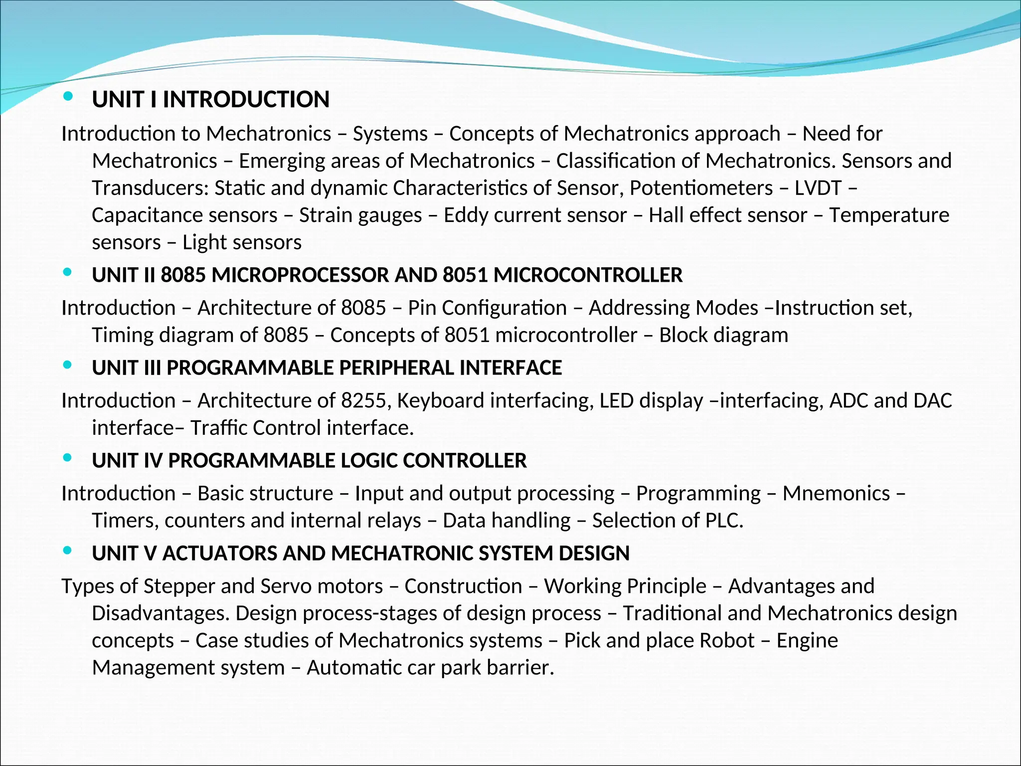
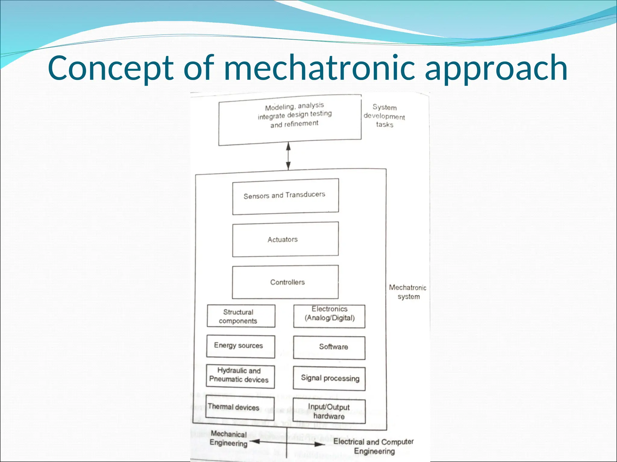
The document outlines the fundamentals of mechatronics, covering its definition, history, and elements such as sensors, actuators, and control systems. It delves into microprocessors and microcontrollers, specifically the 8085 and 8051 architectures, along with types of control systems and actuators used in mechatronic systems. Additionally, it discusses the advantages and disadvantages of mechatronic systems as well as emerging areas and applications in various industries.