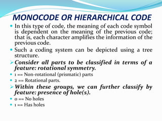
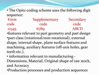
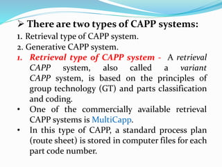
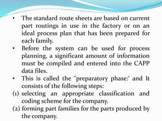
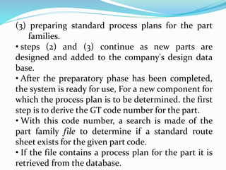
GROUP TECHNOLOGY
FACULTY
MD SHADAB REZA
UNIT – 4
DEPARTMENT OF SCIENCE & TECHNOLOGY
GOVERNMENT POLYTECHNIC PURNEA
DEPARTMENT OF MECHANICAL ENGINEERING
GROUP TECHNOLOGY
 Group Technology is a manufacturing technique in
which similar parts are identified and grouped
together to take the advantage of their similarities
in design and production.
 In group technology parts with similar geometry,
manufacturing process, and/or functions are
manufactured in a single location using a small
number of machines or processes.
 It is based on the general principle that many
problems are similar, and that by grouping similar
problems, a single solution to a set of problems can
be found, which saves time, cost and effort.
• The Objectives of Group Technology are to
Reduce average lot size, Increase part variety,
Increase variety of materials, Achieve close
tolerance, Improve scheduling, Reduce tooling,
Increase equipment utilization etc.
 The benefits of group technology are :
• Reduction in setting up times cost and lot size.
• Reduction in material handling costs.
• Reduction in production planning cost.
• Output is improved due to improved resource
utilization.
• Improved product quality and less scrap.
• Smaller variety of tools, jigs and fixtures.
• Robots can be easily used for material handling.
PART FAMILIES
 A part family is a group of parts having similar
geometry and/or requiring a similar production
process or the processing steps used in their
manufacturing.
 Part families are the most important feature of
group technology.
 Similarities among parts allow them to be
classified into part families and In each part family,
the processing steps are similar.
 The group of machineries used to process an
individual part family is known as a machine cell
that specialize in production of certain part
families.
 Methods to form Part Families
• There are three methods that can be used to
form part families:
I. Manual visual inspection
II. Production flow analysis (PFA)
III.Part Classification and coding system
I. Manual visual inspection- It involves
arranging a set of parts into groups by
visually inspecting the physical
characteristics of the parts by using best
judgment to group parts into appropriate
part families.
II. Production Flow Analysis - PFA is a method
of identifying part families and associated
machine tool grouping by analyzing the route
sheets for parts produced in a given shop.
• It group together the parts that have similar
operation sequences and machine routings.
III. Parts Classification And Coding-
Identifying Similarities And Differences Among
Parts And classifying Them By Means Of A Coding
method.
• Large manufacturing system can be decomposed
into smaller subsystems of part families based on
similarities in part.
PARTS CLASSIFICATION AND CODING
 In parts classification and coding, similarities
among parts are identified, and these
similarities are related in a coding system.
 Coding: assignment of a symbol (or a set of
symbols) to represent information.
 Classification: a procedure that is used to
separate a large group of objects into separate
sub-groups.
 Parts classification and coding requires
examination and analysis of the design and/or
manufacturing attributes of each part.
Part classification as per Attributes
1. Part design attributes
2. Part manufacturing attributes
3. Both design and manufacturing attributes
 Part design attributes – Major dimensions,
Minor dimensions, Basic external shape, Basic
internal shape, Length/diameter ratio, Material
type, Part function , Tolerances , Surface finish
etc
 Part manufacturing attributes - Major
process , Minor process, Operation sequence,
Batch size, Annual production, Machine tools,
Cutting tools, Material type etc.
 Coding methods- Coding methods
are used to classify the parts into part families.
Coding refers to the process of assigning
symbols to the parts.
 The symbols represent design attributes of
parts or manufacturing features of part families.
 Three structures used in classification
and coding schemes are as follows;
I. Monocode or hierarchical code
II.Polycode or chain type
III.Hybrid or mixed code
MONOCODE OR HIERARCHICAL CODE
 In this type of code, the meaning of each code symbol
is dependent on the meaning of the previous code;
that is, each character amplifies the information of the
previous code.
 Such a coding system can be depicted using a tree
structure.
Consider all parts to be classified in terms of a
feature: rotational symmetry.
 1 == Non-rotational (prismatic) parts
 2 == Rotational parts.
Within these groups, we can further classify by
feature: presence of hole(s).
 0 == No holes
 1 == Has holes
POLYCODE OR CHAIN TYPE
 In this method the code symbols are independent
of each symbol in the sequence which is fixed and
not depend on the preceding digit
 Each digit in specific location of the code describes
a unique property of the work piece.
 It is easy to learn and useful in manufacturing
situations where the manufacturing process have
to be described.
 The length of a Polycode may become excessive
because of its unlimited combinational features.
HYBRID OR MIXED CODE
 It is the mixture of both monocode and
polycode systems.
 Mixed code having the advantages of both
systems.
 Most coding systems use this code structure,
A code created by this manner would be
relatively more compact than a pure
polycode while retaining the ability to easily
identify parts with specific characteristics.
PART CLASSIFICATION AND CODING
SYSTEMS
 Part classification and coding systems which
are widely used in manufacturing field for
GT are as follow:
1. OPTIZ system
2. MICLASS system
3. KK-3 system
3. CODE system
4. The DCLASS System
OPTIZ SYSTEM
 This system was developed by H. Opitz of the
University of Aachen in Germany.
 It the most frequently used, of the parts
classification and coding systems.
 It provides a basic framework for understanding
the classification and coding process .
 It can be applied to machined parts, non-
machined parts and purchased parts.
 It considers both design and manufacturing
information.
• The Opitz coding scheme uses the following digit
sequence:
Form Supplementary Secondary
code code code
12345 6789 ABCD
•features relevant to part geometry and part design
•part class (rotational/non-rotational), external
shape, internal shape, plane surface features and
machining, auxiliary features (off-axis holes, gear
teeth etc.).
• information relevant to manufacturing -
Dimensions, Material, Original shape of raw stock,
and Accuracy
•Production processes and production sequences
COMPUTER-AIDED PROCESS PLANNING (CAPP)
 Process planning is defined as an act of preparing
processing documents for the manufacturing of a
piece, part or an assembly, etc.
 If process planning is done by using a computer it is
called Computer-Aided Process Planning(CAPP).
 CAPP is a technique to produce a design that needed
for manufacturing and to give a complete information
to manufacture a product.
 This is widely used due to the quick response and
more flexibility in manufacturing plants.
 This used to set standard timings in operation and
helps in improving the process planning.
 There are two types of CAPP systems:
1. Retrieval type of CAPP system.
2. Generative CAPP system.
1. Retrieval type of CAPP system - A retrieval
CAPP system, also called a variant
CAPP system, is based on the principles of
group technology (GT) and parts classification
and coding.
• One of the commercially available retrieval
CAPP systems is MultiCapp.
• In this type of CAPP, a standard process plan
(route sheet) is stored in computer files for each
part code number.
• The standard route sheets are based on current
part routings in use in the factory or on an
ideal process plan that has been prepared for
each family.
• Before the system can be used for process
planning, a significant amount of information
must be compiled and entered into the CAPP
data files.
• This is called the "preparatory phase:‘ and It
consists of the following steps:
(1) selecting an appropriate classification and
coding scheme for the company.
(2) forming part families for the parts produced by
the company.
(3) preparing standard process plans for the part
families.
• steps (2) and (3) continue as new parts are
designed and added to the company's design data
base.
• After the preparatory phase has been completed,
the system is ready for use, For a new component for
which the process plan is to be determined. the first
step is to derive the GT code number for the part.
• With this code number, a search is made of the
part family file to determine if a standard route
sheet exists for the given part code.
• If the file contains a process plan for the part it is
retrieved from the database.
(hence the word "retrieval" for this CAPP system)
and displayed for the user.
• The standard process plan is examined to
determine whether any modifications are necessary.
• If the file does not contain a standard process plan
for the given code number, the user may search the
computer file for a similar or related code number
for which a standard route sheer does exist.
• Either by editing an existing process plan, or by
starting from scratch, the user prepares the route
sheet for the new part.
• This route sheet becomes the standard process
plan for the new part code number.
2. Generative CAPP system - Generative CAPP
systems represent an alternative approach to
automated process planning.
• Instead of retrieving and editing an existing plan
stored in a computer data base, a generative system
creates the process plan based on logical
procedures similar to the procedures a human
planner would use.
• In a fully generative CAPP system, the process
sequence is planned without human assistance and
without a set of predefined standard plans.
•Designing a generative CAPP system is usually
considered as a part of the field of expert systems, a
branch of artificial intelligence.
• An expert system is a computer program that is
capable of solving complex problems that normally
require a human with years of education and
experience.
• There are several things required in a fully
generative process planning system.
• First, the technical knowledge of manufacturing
and the logic used by successful process planners
must be captured and coded into a computer
program.
• In an expert system applied to process planning,
the knowledge and logic of the human process
planners is integrated into a "knowledge base’’.
• The generative CAPP system then uses that
knowledge base to solve process planning
problems i.e., create route sheets.
• The second requirement is a computer-
compatible description of the part to be produced.
• This description contains all of the relevant data
and information needed to plan the process
sequence, Two possible ways of providing this
description are:
(l) the geometric model of the part that is
developed on a CAD system during product design
(2) a GT code number of the part that defines the
part features in significant detail.
• Third requirement is the capability to apply the
process knowledge and planning logic stored in the
knowledge base to a given part description.
• The CAPP system uses its knowledge base to solve
a specific problem i:e planning the process for a
new part.
• This problem-solving procedure is referred to as
the "inference engine’ in the terminology of expert
systems.
• By using its knowledge base and inference engine,
the CAPP system creates a new process plan for
each new part.

CAD LECTURE 2.pptx

  • 1.
    GROUP TECHNOLOGY FACULTY MD SHADABREZA UNIT – 4 DEPARTMENT OF SCIENCE & TECHNOLOGY GOVERNMENT POLYTECHNIC PURNEA DEPARTMENT OF MECHANICAL ENGINEERING
  • 2.
    GROUP TECHNOLOGY  GroupTechnology is a manufacturing technique in which similar parts are identified and grouped together to take the advantage of their similarities in design and production.  In group technology parts with similar geometry, manufacturing process, and/or functions are manufactured in a single location using a small number of machines or processes.  It is based on the general principle that many problems are similar, and that by grouping similar problems, a single solution to a set of problems can be found, which saves time, cost and effort.
  • 3.
    • The Objectivesof Group Technology are to Reduce average lot size, Increase part variety, Increase variety of materials, Achieve close tolerance, Improve scheduling, Reduce tooling, Increase equipment utilization etc.  The benefits of group technology are : • Reduction in setting up times cost and lot size. • Reduction in material handling costs. • Reduction in production planning cost. • Output is improved due to improved resource utilization. • Improved product quality and less scrap. • Smaller variety of tools, jigs and fixtures. • Robots can be easily used for material handling.
  • 4.
    PART FAMILIES  Apart family is a group of parts having similar geometry and/or requiring a similar production process or the processing steps used in their manufacturing.  Part families are the most important feature of group technology.  Similarities among parts allow them to be classified into part families and In each part family, the processing steps are similar.  The group of machineries used to process an individual part family is known as a machine cell that specialize in production of certain part families.
  • 5.
     Methods toform Part Families • There are three methods that can be used to form part families: I. Manual visual inspection II. Production flow analysis (PFA) III.Part Classification and coding system I. Manual visual inspection- It involves arranging a set of parts into groups by visually inspecting the physical characteristics of the parts by using best judgment to group parts into appropriate part families.
  • 6.
    II. Production FlowAnalysis - PFA is a method of identifying part families and associated machine tool grouping by analyzing the route sheets for parts produced in a given shop. • It group together the parts that have similar operation sequences and machine routings. III. Parts Classification And Coding- Identifying Similarities And Differences Among Parts And classifying Them By Means Of A Coding method. • Large manufacturing system can be decomposed into smaller subsystems of part families based on similarities in part.
  • 7.
    PARTS CLASSIFICATION ANDCODING  In parts classification and coding, similarities among parts are identified, and these similarities are related in a coding system.  Coding: assignment of a symbol (or a set of symbols) to represent information.  Classification: a procedure that is used to separate a large group of objects into separate sub-groups.  Parts classification and coding requires examination and analysis of the design and/or manufacturing attributes of each part.
  • 8.
    Part classification asper Attributes 1. Part design attributes 2. Part manufacturing attributes 3. Both design and manufacturing attributes  Part design attributes – Major dimensions, Minor dimensions, Basic external shape, Basic internal shape, Length/diameter ratio, Material type, Part function , Tolerances , Surface finish etc  Part manufacturing attributes - Major process , Minor process, Operation sequence, Batch size, Annual production, Machine tools, Cutting tools, Material type etc.
  • 9.
     Coding methods-Coding methods are used to classify the parts into part families. Coding refers to the process of assigning symbols to the parts.  The symbols represent design attributes of parts or manufacturing features of part families.  Three structures used in classification and coding schemes are as follows; I. Monocode or hierarchical code II.Polycode or chain type III.Hybrid or mixed code
  • 10.
    MONOCODE OR HIERARCHICALCODE  In this type of code, the meaning of each code symbol is dependent on the meaning of the previous code; that is, each character amplifies the information of the previous code.  Such a coding system can be depicted using a tree structure. Consider all parts to be classified in terms of a feature: rotational symmetry.  1 == Non-rotational (prismatic) parts  2 == Rotational parts. Within these groups, we can further classify by feature: presence of hole(s).  0 == No holes  1 == Has holes
  • 12.
    POLYCODE OR CHAINTYPE  In this method the code symbols are independent of each symbol in the sequence which is fixed and not depend on the preceding digit  Each digit in specific location of the code describes a unique property of the work piece.  It is easy to learn and useful in manufacturing situations where the manufacturing process have to be described.  The length of a Polycode may become excessive because of its unlimited combinational features.
  • 14.
    HYBRID OR MIXEDCODE  It is the mixture of both monocode and polycode systems.  Mixed code having the advantages of both systems.  Most coding systems use this code structure, A code created by this manner would be relatively more compact than a pure polycode while retaining the ability to easily identify parts with specific characteristics.
  • 16.
    PART CLASSIFICATION ANDCODING SYSTEMS  Part classification and coding systems which are widely used in manufacturing field for GT are as follow: 1. OPTIZ system 2. MICLASS system 3. KK-3 system 3. CODE system 4. The DCLASS System
  • 17.
    OPTIZ SYSTEM  Thissystem was developed by H. Opitz of the University of Aachen in Germany.  It the most frequently used, of the parts classification and coding systems.  It provides a basic framework for understanding the classification and coding process .  It can be applied to machined parts, non- machined parts and purchased parts.  It considers both design and manufacturing information.
  • 18.
    • The Opitzcoding scheme uses the following digit sequence: Form Supplementary Secondary code code code 12345 6789 ABCD •features relevant to part geometry and part design •part class (rotational/non-rotational), external shape, internal shape, plane surface features and machining, auxiliary features (off-axis holes, gear teeth etc.). • information relevant to manufacturing - Dimensions, Material, Original shape of raw stock, and Accuracy •Production processes and production sequences
  • 19.
    COMPUTER-AIDED PROCESS PLANNING(CAPP)  Process planning is defined as an act of preparing processing documents for the manufacturing of a piece, part or an assembly, etc.  If process planning is done by using a computer it is called Computer-Aided Process Planning(CAPP).  CAPP is a technique to produce a design that needed for manufacturing and to give a complete information to manufacture a product.  This is widely used due to the quick response and more flexibility in manufacturing plants.  This used to set standard timings in operation and helps in improving the process planning.
  • 20.
     There aretwo types of CAPP systems: 1. Retrieval type of CAPP system. 2. Generative CAPP system. 1. Retrieval type of CAPP system - A retrieval CAPP system, also called a variant CAPP system, is based on the principles of group technology (GT) and parts classification and coding. • One of the commercially available retrieval CAPP systems is MultiCapp. • In this type of CAPP, a standard process plan (route sheet) is stored in computer files for each part code number.
  • 21.
    • The standardroute sheets are based on current part routings in use in the factory or on an ideal process plan that has been prepared for each family. • Before the system can be used for process planning, a significant amount of information must be compiled and entered into the CAPP data files. • This is called the "preparatory phase:‘ and It consists of the following steps: (1) selecting an appropriate classification and coding scheme for the company. (2) forming part families for the parts produced by the company.
  • 22.
    (3) preparing standardprocess plans for the part families. • steps (2) and (3) continue as new parts are designed and added to the company's design data base. • After the preparatory phase has been completed, the system is ready for use, For a new component for which the process plan is to be determined. the first step is to derive the GT code number for the part. • With this code number, a search is made of the part family file to determine if a standard route sheet exists for the given part code. • If the file contains a process plan for the part it is retrieved from the database.
  • 23.
    (hence the word"retrieval" for this CAPP system) and displayed for the user. • The standard process plan is examined to determine whether any modifications are necessary. • If the file does not contain a standard process plan for the given code number, the user may search the computer file for a similar or related code number for which a standard route sheer does exist. • Either by editing an existing process plan, or by starting from scratch, the user prepares the route sheet for the new part. • This route sheet becomes the standard process plan for the new part code number.
  • 24.
    2. Generative CAPPsystem - Generative CAPP systems represent an alternative approach to automated process planning. • Instead of retrieving and editing an existing plan stored in a computer data base, a generative system creates the process plan based on logical procedures similar to the procedures a human planner would use. • In a fully generative CAPP system, the process sequence is planned without human assistance and without a set of predefined standard plans. •Designing a generative CAPP system is usually considered as a part of the field of expert systems, a branch of artificial intelligence.
  • 25.
    • An expertsystem is a computer program that is capable of solving complex problems that normally require a human with years of education and experience. • There are several things required in a fully generative process planning system. • First, the technical knowledge of manufacturing and the logic used by successful process planners must be captured and coded into a computer program. • In an expert system applied to process planning, the knowledge and logic of the human process planners is integrated into a "knowledge base’’.
  • 26.
    • The generativeCAPP system then uses that knowledge base to solve process planning problems i.e., create route sheets. • The second requirement is a computer- compatible description of the part to be produced. • This description contains all of the relevant data and information needed to plan the process sequence, Two possible ways of providing this description are: (l) the geometric model of the part that is developed on a CAD system during product design (2) a GT code number of the part that defines the part features in significant detail.
  • 27.
    • Third requirementis the capability to apply the process knowledge and planning logic stored in the knowledge base to a given part description. • The CAPP system uses its knowledge base to solve a specific problem i:e planning the process for a new part. • This problem-solving procedure is referred to as the "inference engine’ in the terminology of expert systems. • By using its knowledge base and inference engine, the CAPP system creates a new process plan for each new part.