Download to read offline


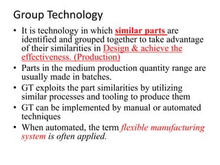


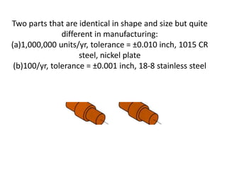


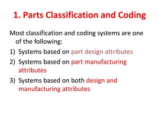


Group technology is a manufacturing strategy that involves grouping similar parts together and processing them in the same production cells using similar machines and tools. The key aspects are: - Identifying part families based on similarities in geometry, manufacturing processes, etc. - Organizing production facilities into manufacturing cells specialized for certain part families to reduce setup times and transportation. - Implementing flexible manufacturing systems and just-in-time production to further improve efficiency. - Classification and coding systems help systematically identify part similarities and differences to effectively group parts into families.