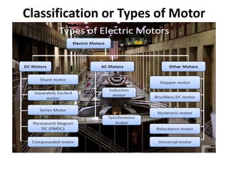
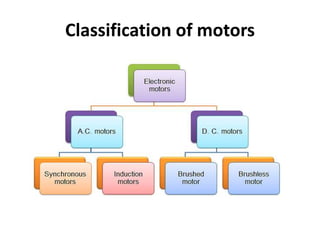
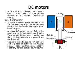
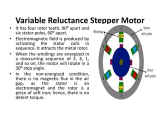
Electrical Motor
• A motor is nothing but an electro-mechanical
device that converts electrical energy to
mechanical energy.
• The very basic principal of functioning of an
electrical motor lies on the fact that force is
experienced in the direction perpendicular to
magnetic field and the current, when field and
current are made to interact with each other.
Classification or Types of Motor
Classification of motors
DC motors
• A DC motor is a device that converts
direct current (electrical energy) into
rotation of an element (mechanical
energy).
Brush type DC motor
• A typical brushed motor consists of an
armature coil, slip rings divided into two
parts, a pair of brushes and horse shoes
electromagnet.
• A simple DC motor has two field poles
namely a north pole and a south pole.
The magnetic lines of force extend across
the opening between the poles from
north to south.
• The coil is wound around a soft iron core
and is placed in between the magnet
poles. These electromagnets receive
electricity from an outside power source.
Advantages of brushed DC motor:
• The design of the brushed DC motor is quite
simple
• Controlling the speed of a Brush DC Motor is easy
• Very cost effective
Disadvantages of brushed DC motor:
• High maintenance
• Performance decreases with dust particles
• Less reliable in control at lower speeds
• The brushes wear off with usage
Brushless DC motor
• A brushless DC motor has a rotor with
permanent magnets and a stator with
windings. The rotor can be of ceramic
permanent magnet type.
• The brushes and commutator are
eliminated and the windings are
connected to the control electronics.
• The control electronics replace the
commutator and brushes and energize
the stator sequentially. Here the
conductor is fixed and the magnet
moves.
• The current supplied to the stator is
based on the position of rotor. It is
switched in sequence using transistors.
The position of the rotor is sensed by
Hall effect sensors. Thus a continuous
rotation is obtained.
Advantages of brushless DC motor:
• More precise due to computer control
• More efficient
• No sparking due to absence of brushes
• Less electrical noise
• No brushes to wear out
• Electromagnets are situated on the stator hence easy to cool
• Motor can operate at speeds above 10,000 rpm under loaded and
unloaded conditions
• Responsiveness and quick acceleration due to low rotor inertia
Disadvantages of brushless DC motor:
• Higher initial cost
• Complex due to presence of computer controller
• Brushless DC motor also requires additional system wiring in order to
power the electronic commutation circuitry
AC motors
• AC motors convert AC current into the rotation of
a mechanical element (mechanical energy).
• As in the case of DC motor, a current is passed
through the coil, generating a torque on the coil.
Typical components include a stator and a rotor.
• The main limitation of AC motors over DC motors
is that speed is more difficult to control in AC
motors. To overcome this limitation, AC motors
are equipped with variable frequency drives but
the improved speed control.
Synchronous motor
• A synchronous motor is an AC motor which runs at constant speed fixed
by frequency of the system.
• It requires direct current (DC) for excitation and has low starting torque,
and hence is suited for applications that start with a low load. It has two
basic electrical parts namely stator and rotor.
• The main difference between the synchronous motor and the induction
motor is that the rotor of the synchronous motor travels at the same
speed as the rotating magnet.
• The stator is given a three phase supply and as the polarity of the stator
progressively change the magnetic field rotates, the rotor will follow and
rotate with the magnetic field of the stator.
• 𝑁𝑠= 120∗𝑓/𝑃
• Ns = Revolutions per minute
• P = Number of pole pairs
• f = Applied frequency
Induction motor
Rotor of an induction motor can be of two types:
• A squirrel-cage rotor consists of thick
conducting bars embedded in parallel slots.
The bars can be of copper or aluminum. These
bars are fitted at both ends by means end rings
as
• A wound rotor has a three-phase, double-layer,
distributed winding. The rotor is wound for as
many numbers of poles as the stator. The three
phases are wired internally and the other ends
are connected to slip-rings mounted on a shaft
with brushes resting on them.
Induction motors can be classified into two types:
• Single-phase induction motor: It has one stator
winding and a squirrel cage rotor. It operates
with a single-phase power supply and requires
a device to start the motor.
• Three-phase induction motor: The rotating
magnetic field is produced by the balanced
three-phase power supply. These motors can
have squirrel cage or wound rotors and are
self-starting.
Stepper motor
• A stepper motor is a pulse-driven motor that changes
the angular position of the rotor in steps. Due to this
nature of a stepper motor, it is widely used in low cost,
open loop position control systems.
Types of stepper motors:
1.Permanent Magnet
• Employ permanent magnet
• Low speed, relatively high torque
2. Variable Reluctance
• Does not have permanent magnet
• Low torque
Permanent magnet (PM) stepper
motor
• In this type of motor, the rotor is a
permanent magnet.
• Unlike the other stepping motors,
the PM motor rotor has no teeth
and is designed to be magnetized at
a right angle to its axis.
• Applying current to each phase in
sequence will cause the rotor to
rotate by adjusting to the changing
magnetic fields.
• Although it operates at fairly low
speed, the PM motor has a relatively
high torque characteristic. These are
low cost motors with typical step
angle ranging between 7.5⁰ to 15⁰.
Variable Reluctance Stepper Motor
• It has four rotor teeth, 90⁰ apart and
six stator poles, 60⁰ apart.
• Electromagnetic field is produced by
activating the stator coils in
sequence. It attracts the metal rotor.
• When the windings are energized in
a reoccurring sequence of 2, 3, 1,
and so on, the motor will rotate in a
30⁰ step angle.
• In the non-energized condition,
there is no magnetic flux in the air
gap, as the stator is an
electromagnet and the rotor is a
piece of soft iron; hence, there is no
detent torque.
Properties
• It can rotate in both directions
• It can move in precise angular movement
• It can sustain a holding torque at zero speed
• It can be controlled with digital circuits.
Step mode of stepper motors
• Full step mode – 200 steps/rev
• Half step mode – 400 steps/rev
• Micro step mode – 1/256 of a step or 50,000
steps / rev
Applications
• Floppy disc drive
• Positioning of print head
• NC and CNC machine tool slide drives
• Camera iris control mechanism
• Automatic teller machine
• Paper feed motors in typewriters and printers
Servo motors
• Fast response
• High accuracy
• Fast and accurate speed
• Very high starting torque
• Unattended control
• Direction control
• Remote operation
Applications
• Toy car for controlling direction of motion
• RC helicopter and planes
• Robotics
• CD/DVD Players
• CNC machine
Closed loop servo system
Servo motor control system

20ME702– MECHATRONICS -UNIT-5-Motor.ppt

  • 1.
    Electrical Motor • Amotor is nothing but an electro-mechanical device that converts electrical energy to mechanical energy. • The very basic principal of functioning of an electrical motor lies on the fact that force is experienced in the direction perpendicular to magnetic field and the current, when field and current are made to interact with each other.
  • 2.
  • 3.
  • 4.
    DC motors • ADC motor is a device that converts direct current (electrical energy) into rotation of an element (mechanical energy). Brush type DC motor • A typical brushed motor consists of an armature coil, slip rings divided into two parts, a pair of brushes and horse shoes electromagnet. • A simple DC motor has two field poles namely a north pole and a south pole. The magnetic lines of force extend across the opening between the poles from north to south. • The coil is wound around a soft iron core and is placed in between the magnet poles. These electromagnets receive electricity from an outside power source.
  • 5.
    Advantages of brushedDC motor: • The design of the brushed DC motor is quite simple • Controlling the speed of a Brush DC Motor is easy • Very cost effective Disadvantages of brushed DC motor: • High maintenance • Performance decreases with dust particles • Less reliable in control at lower speeds • The brushes wear off with usage
  • 6.
    Brushless DC motor •A brushless DC motor has a rotor with permanent magnets and a stator with windings. The rotor can be of ceramic permanent magnet type. • The brushes and commutator are eliminated and the windings are connected to the control electronics. • The control electronics replace the commutator and brushes and energize the stator sequentially. Here the conductor is fixed and the magnet moves. • The current supplied to the stator is based on the position of rotor. It is switched in sequence using transistors. The position of the rotor is sensed by Hall effect sensors. Thus a continuous rotation is obtained.
  • 7.
    Advantages of brushlessDC motor: • More precise due to computer control • More efficient • No sparking due to absence of brushes • Less electrical noise • No brushes to wear out • Electromagnets are situated on the stator hence easy to cool • Motor can operate at speeds above 10,000 rpm under loaded and unloaded conditions • Responsiveness and quick acceleration due to low rotor inertia Disadvantages of brushless DC motor: • Higher initial cost • Complex due to presence of computer controller • Brushless DC motor also requires additional system wiring in order to power the electronic commutation circuitry
  • 8.
    AC motors • ACmotors convert AC current into the rotation of a mechanical element (mechanical energy). • As in the case of DC motor, a current is passed through the coil, generating a torque on the coil. Typical components include a stator and a rotor. • The main limitation of AC motors over DC motors is that speed is more difficult to control in AC motors. To overcome this limitation, AC motors are equipped with variable frequency drives but the improved speed control.
  • 9.
    Synchronous motor • Asynchronous motor is an AC motor which runs at constant speed fixed by frequency of the system. • It requires direct current (DC) for excitation and has low starting torque, and hence is suited for applications that start with a low load. It has two basic electrical parts namely stator and rotor. • The main difference between the synchronous motor and the induction motor is that the rotor of the synchronous motor travels at the same speed as the rotating magnet. • The stator is given a three phase supply and as the polarity of the stator progressively change the magnetic field rotates, the rotor will follow and rotate with the magnetic field of the stator. • 𝑁𝑠= 120∗𝑓/𝑃 • Ns = Revolutions per minute • P = Number of pole pairs • f = Applied frequency
  • 10.
    Induction motor Rotor ofan induction motor can be of two types: • A squirrel-cage rotor consists of thick conducting bars embedded in parallel slots. The bars can be of copper or aluminum. These bars are fitted at both ends by means end rings as • A wound rotor has a three-phase, double-layer, distributed winding. The rotor is wound for as many numbers of poles as the stator. The three phases are wired internally and the other ends are connected to slip-rings mounted on a shaft with brushes resting on them. Induction motors can be classified into two types: • Single-phase induction motor: It has one stator winding and a squirrel cage rotor. It operates with a single-phase power supply and requires a device to start the motor. • Three-phase induction motor: The rotating magnetic field is produced by the balanced three-phase power supply. These motors can have squirrel cage or wound rotors and are self-starting.
  • 11.
    Stepper motor • Astepper motor is a pulse-driven motor that changes the angular position of the rotor in steps. Due to this nature of a stepper motor, it is widely used in low cost, open loop position control systems. Types of stepper motors: 1.Permanent Magnet • Employ permanent magnet • Low speed, relatively high torque 2. Variable Reluctance • Does not have permanent magnet • Low torque
  • 12.
    Permanent magnet (PM)stepper motor • In this type of motor, the rotor is a permanent magnet. • Unlike the other stepping motors, the PM motor rotor has no teeth and is designed to be magnetized at a right angle to its axis. • Applying current to each phase in sequence will cause the rotor to rotate by adjusting to the changing magnetic fields. • Although it operates at fairly low speed, the PM motor has a relatively high torque characteristic. These are low cost motors with typical step angle ranging between 7.5⁰ to 15⁰.
  • 13.
    Variable Reluctance StepperMotor • It has four rotor teeth, 90⁰ apart and six stator poles, 60⁰ apart. • Electromagnetic field is produced by activating the stator coils in sequence. It attracts the metal rotor. • When the windings are energized in a reoccurring sequence of 2, 3, 1, and so on, the motor will rotate in a 30⁰ step angle. • In the non-energized condition, there is no magnetic flux in the air gap, as the stator is an electromagnet and the rotor is a piece of soft iron; hence, there is no detent torque.
  • 14.
    Properties • It canrotate in both directions • It can move in precise angular movement • It can sustain a holding torque at zero speed • It can be controlled with digital circuits.
  • 15.
    Step mode ofstepper motors • Full step mode – 200 steps/rev • Half step mode – 400 steps/rev • Micro step mode – 1/256 of a step or 50,000 steps / rev
  • 16.
    Applications • Floppy discdrive • Positioning of print head • NC and CNC machine tool slide drives • Camera iris control mechanism • Automatic teller machine • Paper feed motors in typewriters and printers
  • 17.
    Servo motors • Fastresponse • High accuracy • Fast and accurate speed • Very high starting torque • Unattended control • Direction control • Remote operation
  • 18.
    Applications • Toy carfor controlling direction of motion • RC helicopter and planes • Robotics • CD/DVD Players • CNC machine
  • 19.
  • 20.