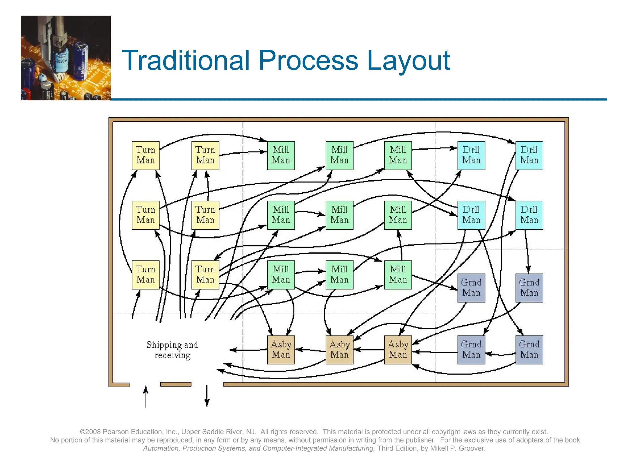
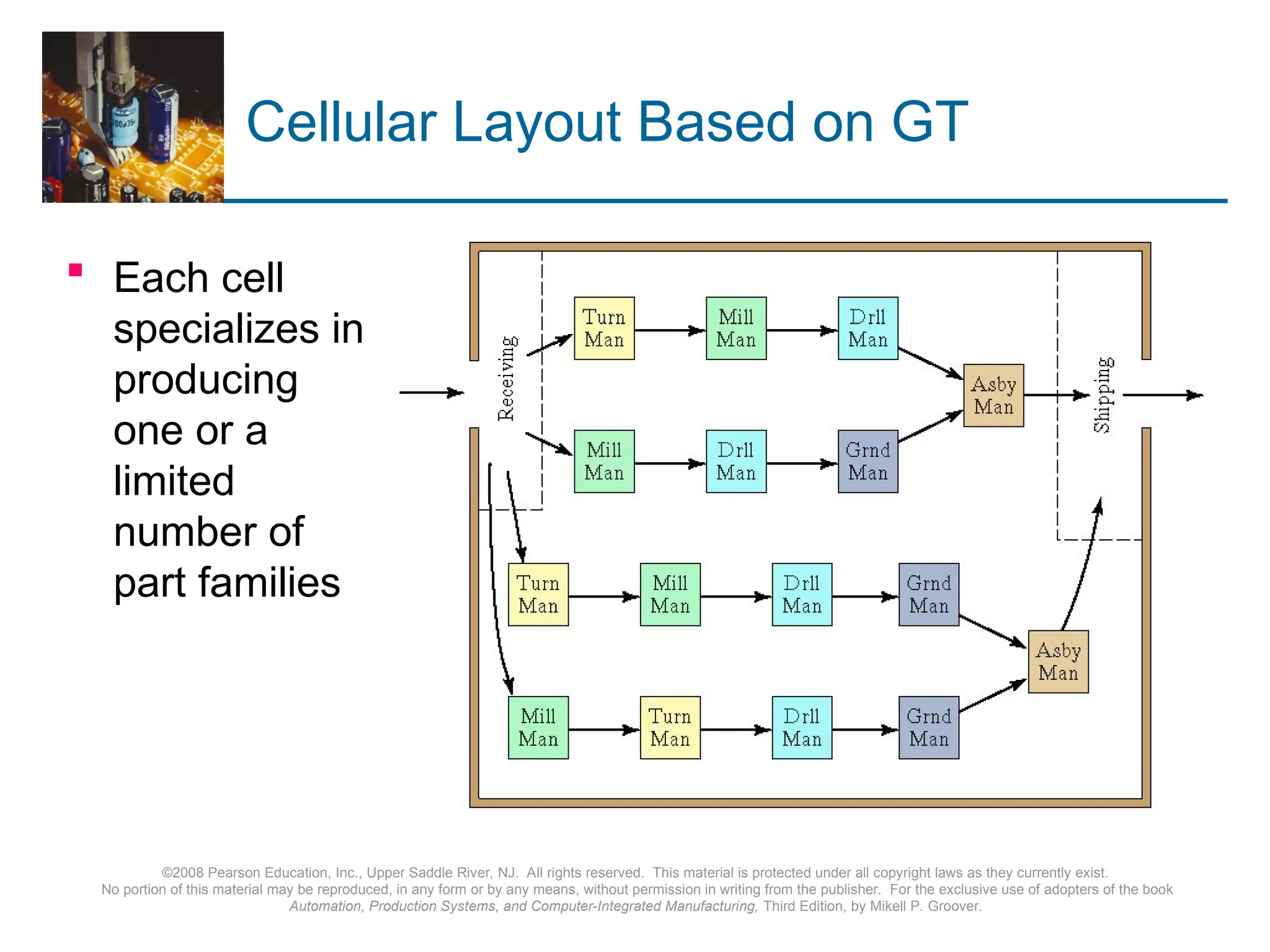
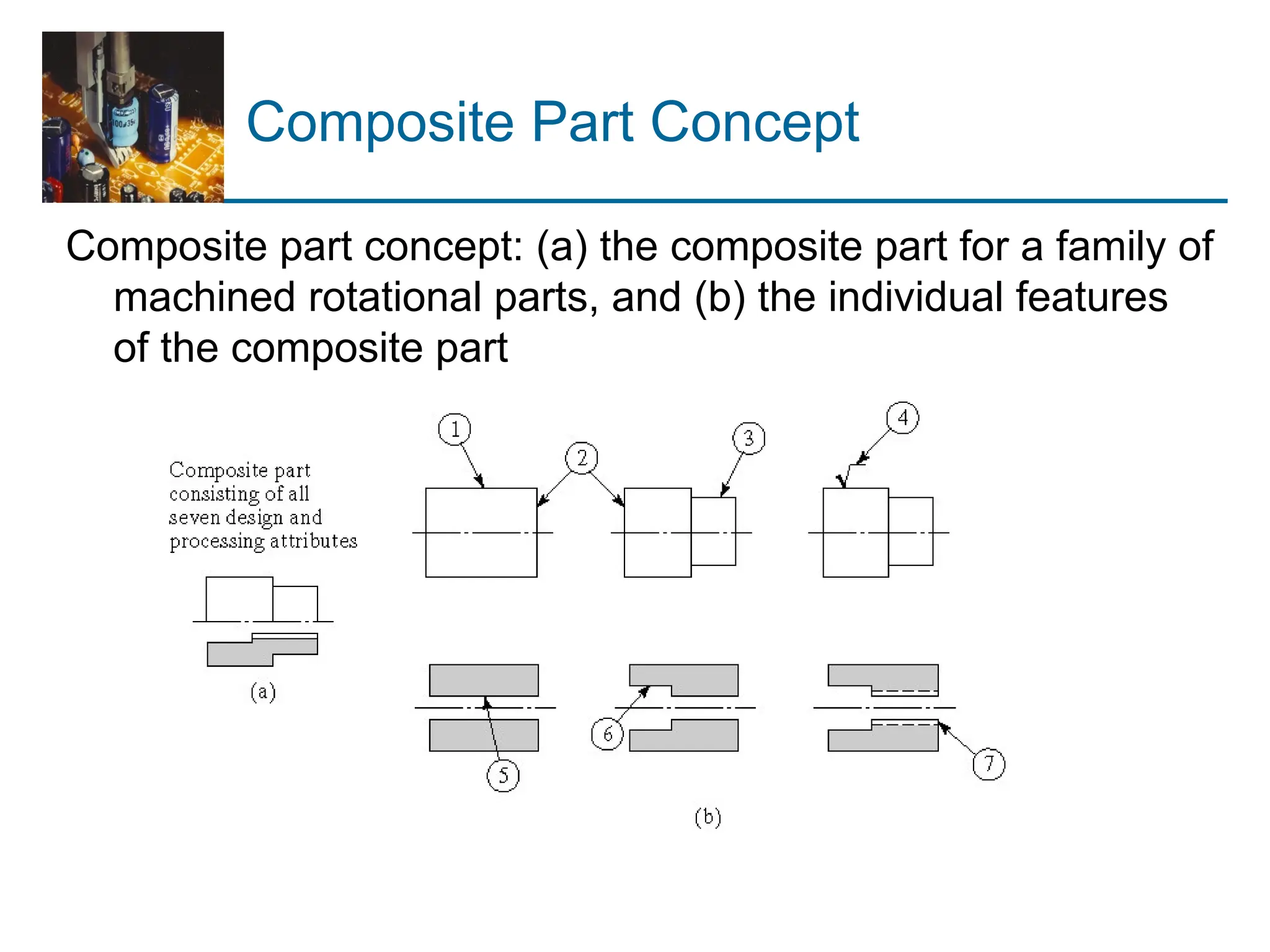
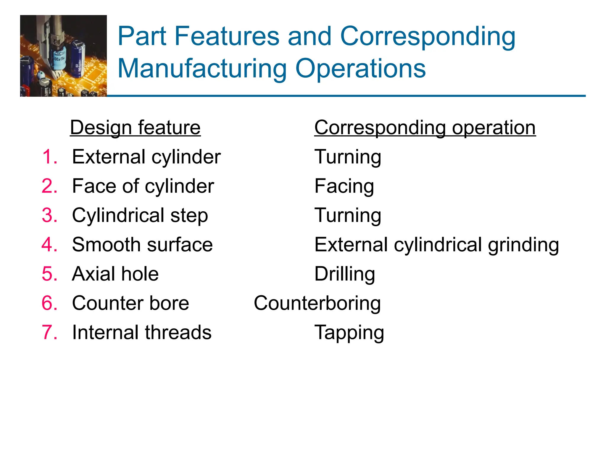
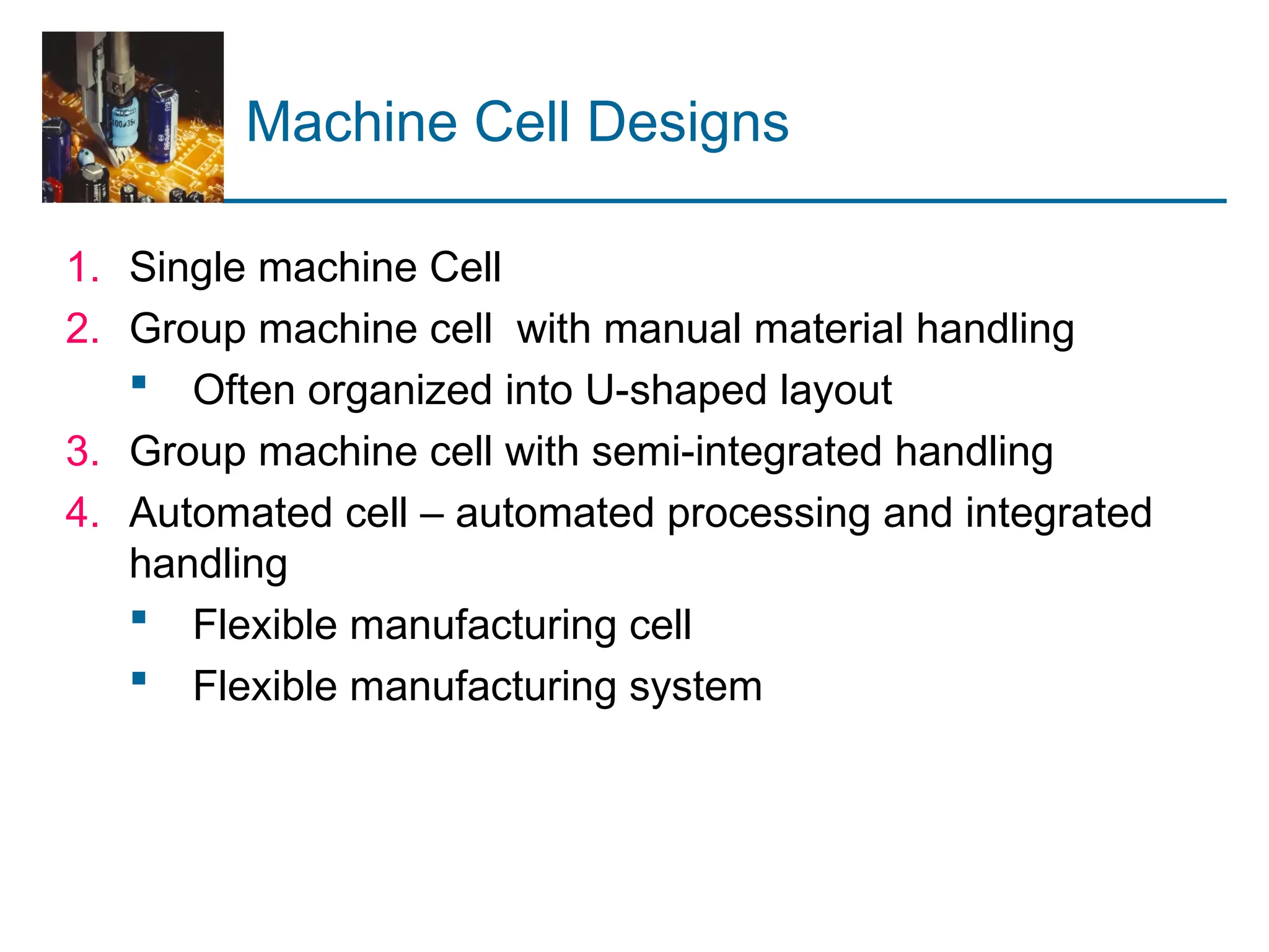
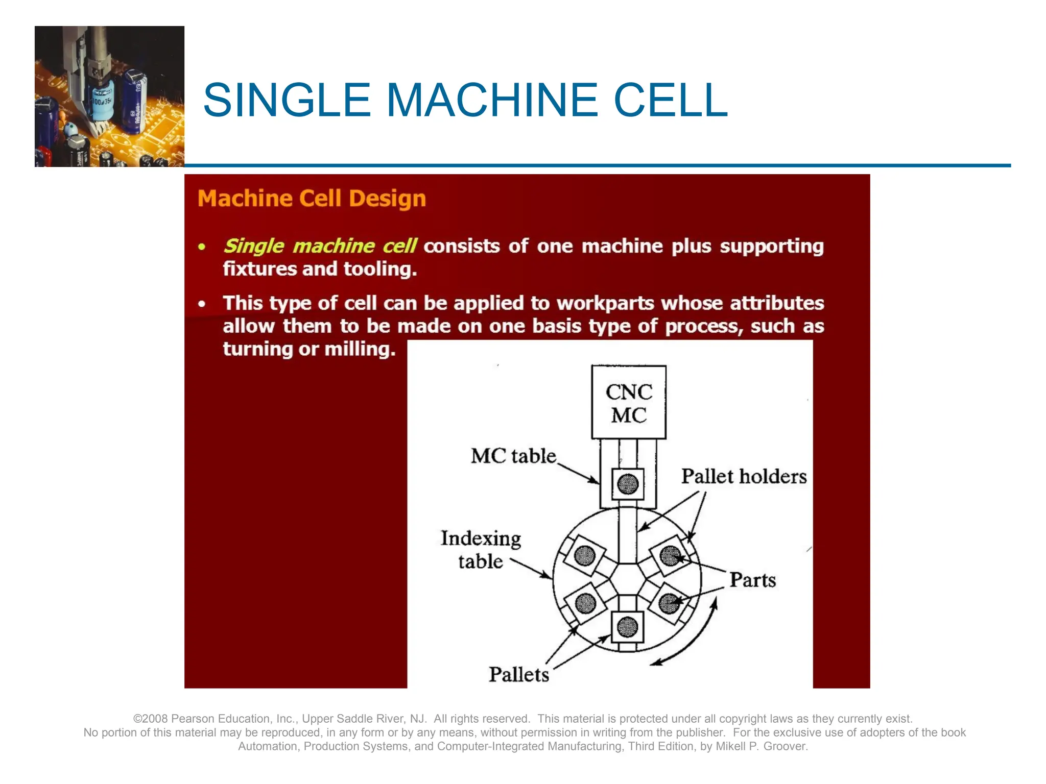
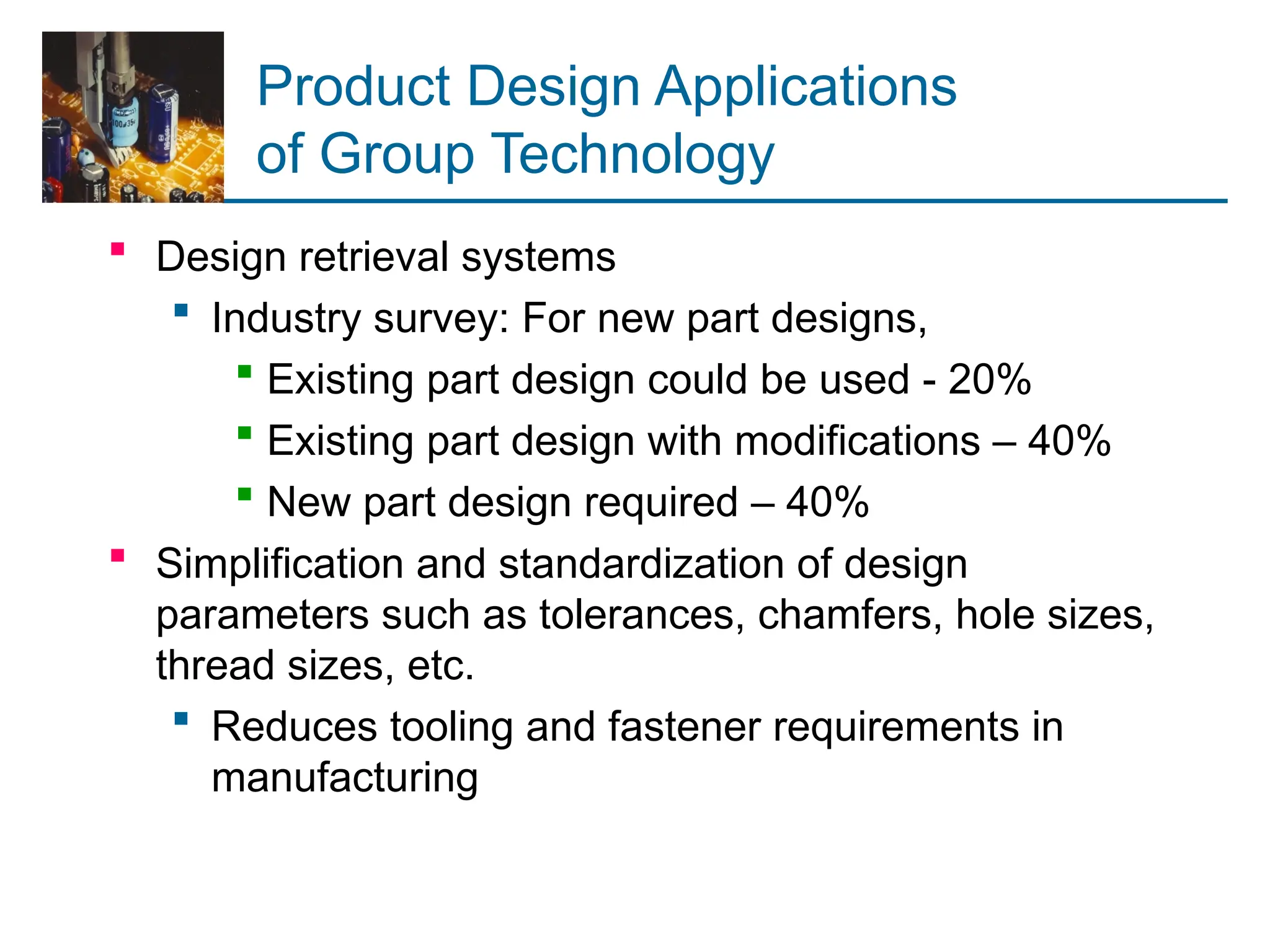
Group Technology (GT) Defined
Group Technology also known as GT, is a
manufacturing technology where similar parts
are collectively identified and grouped to use
the benefit of their relationship in design and
as well as in production.
The similar parts are grouped to form part
families.
Each and every family has similar design and
manufacturing qualities
A manufacturing philosophy in which similar parts are identified
and grouped together to take advantage of their similarities in
design and production
Similarities among parts permit them to be classified into part
families
In each part family, processing steps are similar
The improvement is typically achieved by organizing the
production facilities into manufacturing cells that specialize in
production of certain part families
Overview of Group Technology
 Parts in the medium production quantity range are usually
made in batches
 Disadvantages of batch production:
 Downtime for changeovers
 High inventory carrying costs
 GT minimizes these disadvantages by recognizing that
although the parts are different, there are groups of parts
that possess similarities
Why Group Technology?
 By performing similar activities together, thereby
avoiding wasteful time in changing from one
unrelated activity to the next.
 By standardizing closely related activities, thereby
focusing only on distinct differences and avoiding
unnecessary duplication of effort.
 By efficiently storing and retrieving information
related to recurring problems, thereby reducing the
search time for the information and eliminating the
need to solve the problem again.
Advantages of GT
 Reductions in throughput time set-up time overdue orders
 Production floor space raw material stocks in-process inventory
 Capital expenditures tooling costs engineering time and costs
 New parts design new shop drawings total number of drawings
 Easier to justify automation
 Standardization in design
 Data retrieval
 Easier, more standardized process plans
 Increases in quality
When to Use GT and
Cellular Manufacturing
1. The plant currently uses traditional batch production and
a process type layout
 This results in much material handling effort, high in-
process inventory, and long manufacturing lead times
2. The parts can be grouped into part families
 A necessary condition to apply group technology
 Each machine cell is designed to produce a given part
family, or a limited collection of part families, so it must
be possible to group parts made in the plant into
families
Problems in Implementing GT
1. Identifying the part families
 Reviewing all of the parts made in the plant and
grouping them into part families is a substantial
task
2. Rearranging production machines into GT cells
 It is time-consuming and costly to physically
rearrange the machines into cells, and the
machines are not producing during the
changeover
Part Family
A collection of parts that possess similarities in geometric
shape and size, or in the processing steps used in their
manufacture
 Part families are a central feature of group technology
 There are always differences among parts in a family
 But the similarities are close enough that the parts can
be grouped into the same family
Part Families
 Two parts that are identical in shape and size but quite
different in manufacturing: (a) 1,000,000 units/yr, tolerance
= 0.010 inch, 1015 CR steel, nickel plate; (b) 100/yr,
tolerance = 0.001 inch, 18 8 stainless steel
‑
Part Families
 Ten parts are different in
size, shape, and material,
but quite similar in terms
of manufacturing
 All parts are machined
from cylindrical stock by
turning; some parts
require drilling and/or
milling
©2008 Pearson Education, Inc., Upper Saddle River, NJ. All rights reserved. This material is protected under all copyright laws as they currently exist.
No portion of this material may be reproduced, in any form or by any means, without permission in writing from the publisher. For the exclusive use of adopters of the book
Automation, Production Systems, and Computer-Integrated Manufacturing, Third Edition, by Mikell P. Groover.
Traditional Process Layout
©2008 Pearson Education, Inc., Upper Saddle River, NJ. All rights reserved. This material is protected under all copyright laws as they currently exist.
No portion of this material may be reproduced, in any form or by any means, without permission in writing from the publisher. For the exclusive use of adopters of the book
Automation, Production Systems, and Computer-Integrated Manufacturing, Third Edition, by Mikell P. Groover.
Cellular Layout Based on GT
 Each cell
specializes in
producing
one or a
limited
number of
part families
Ways to Identify Part Families
1. Visual inspection
 Using best judgment to group parts into appropriate
families, based on the parts or photos of the parts
2. Parts classification and coding
 Identifying similarities and differences among parts
and relating them by means of a coding scheme
3. Production flow analysis
 Using information contained on route sheets to
classify parts
visual inspection
 The visual inspection method is the least
sophisticated and least expensive
 method. It involves the classification of parts into
families by looking at either the physical parts or their
photographs and arranging them into groups having
similar features.
Parts Classification and Coding
Identification of similarities among parts and relating the
similarities by means of a numerical coding system
 Most time consuming of the three methods
 Must be customized for a given company or industry
 Reasons for using a coding scheme:
 Design retrieval
 Automated process planning
 Machine cell design
Features of Parts Classification and
Coding Systems
 Most classification and coding systems are based on one
of the following:
 Part design attributes
 Part manufacturing attributes
 Both design and manufacturing attributes
Part Design Attributes
 Major dimensions
 Basic external shape
 Basic internal shape
 Length/diameter ratio
 Material type
 Part function
 Tolerances
 Surface finish
Part Manufacturing Attributes
 Major process
 Operation sequence
 Batch size
 Annual production
 Machine tools
 Cutting tools
 Material type
Coding Scheme Structures
1. Hierarchical structure (monocode)
 Interpretation of each successive digit depends on
the value of the preceding digit
2. Chain-type structure (polycode)
 Interpretation of each symbol is always the same
 No dependence on previous digits
3. Mixed-code structure
 Combination of hierarchical and chain-type
structures
Hierarchical structure (monocode)
 interpretation of each successive symbol depends on the
value of the preceding symbols.
Hierarchical structure (monocode)
Attribute code or Chain-type structure
(polycode)
 in which the interpretation of each symbol in the sequence
is always the same, it does not depend on the value of the
preceding symbols.
Hybrid structure or Decision Tree
 a combination of hierarchical and chain-type structures.
CODING SYSTEMS
 Opitz Classification System
 MICLASS system
 DCLASS system
 KK-3 system
 CODE system
 CUTPLAN system
 RNC system
 Part analog system
 Brisch system
 coform
Opitz Classification System
 One of the first published classification and coding
schemes for mechanical parts
 Basic code = nine (9) digits
 Digits 1 through 5 = form code – primary shape and
design attributes (hierarchical structure)
 Digits 6 through 9 = supplementary code – attributes
that are useful in manufacturing (e.g., dimensions,
starting material)
 Digits 10 through 13 = secondary code – production
operation type and sequence
Basic Structure of Opitz System
Opitz Form Code (Digits 1 through 5)
Example: Opitz Form Code
Form code in Opitz system is 15100
Production Flow Analysis (PFA)
Method for identifying part families and associated machine
groupings based on production route sheets rather than
part design data
 Workparts with identical or similar route sheets are
classified into part families
 Advantages of using route sheet data
 Parts with different geometries may nevertheless
require the same or similar processing
 Parts with nearly the same geometries may
nevertheless require different processing
Steps in Production Flow Analysis
1. Data collection – operation sequence and machine
routing for each part
2. Sortation of process routings – parts with same
sequences and routings are arranged into “packs”
3. PFA chart – each pack is displayed on a PFA chart
 Also called a part-machine incidence matrix
4. Cluster analysis – purpose is to collect packs with similar
routings into groups
 Each machine group = a machine cell
Cellular Manufacturing
Application of group technology in which dissimilar
machines or processes are aggregated into cells, each of
which is dedicated to the production of a part family or
limited group of families
 Typical objectives of cellular manufacturing:
 To shorten manufacturing lead times
 To reduce WIP
 To improve quality
 To simplify production scheduling
 To reduce setup times
Composite Part Concept
A composite part for a given family is a hypothetical part that
includes all of the design and manufacturing attributes of
the family
 In general, an individual part in the family will have some
of the features of the family, but not all of them
 A production cell for the part family would consist of those
machines required to make the composite part
 Such a cell would be able to produce any family member,
by omitting operations corresponding to features not
possessed by that part
Composite Part Concept
Composite part concept: (a) the composite part for a family of
machined rotational parts, and (b) the individual features
of the composite part
Part Features and Corresponding
Manufacturing Operations
Design feature Corresponding operation
1. External cylinder Turning
2. Face of cylinder Facing
3. Cylindrical step Turning
4. Smooth surface External cylindrical grinding
5. Axial hole Drilling
6. Counter bore Counterboring
7. Internal threads Tapping
Machine Cell Designs
1. Single machine Cell
2. Group machine cell with manual material handling
 Often organized into U-shaped layout
3. Group machine cell with semi-integrated handling
4. Automated cell – automated processing and integrated
handling
 Flexible manufacturing cell
 Flexible manufacturing system
SINGLE MACHINE CELL
©2008 Pearson Education, Inc., Upper Saddle River, NJ. All rights reserved. This material is protected under all copyright laws as they currently exist.
No portion of this material may be reproduced, in any form or by any means, without permission in writing from the publisher. For the exclusive use of adopters of the book
Automation, Production Systems, and Computer-Integrated Manufacturing, Third Edition, by Mikell P. Groover.
Machine Cell with Manual Handling
U-shaped machine cell with manual part handling between
machines
Cell with Semi-Integrated Handling
In-line layout using mechanized work handling between
machines
Cell with Semi-Integrated Handling
Loop layout allows variations in part routing between
machines
Cell with Semi-Integrated Handling
Rectangular layout also allows variations in part routing and
allows for return of work carriers if they are used
Four Types of Part Moves in
Mixed Model Production System
Key Machine Concept
 Applies in cells when there is one machine (the key
machine) that is more expensive or performs certain
critical operations
 Other machines in the cell are supporting machines
 Important to maintain high utilization of key machine,
even if this means lower utilization of supporting
machines
Manufacturing Applications
of Group Technology
 Different ways of forming machine cells:
 Informal scheduling and routing of similar parts
through selected machines to minimize setups
 Virtual machine cells – dedication of certain
machines in the factory to produce part families,
but no physical relocation of machines
 Formal machine cells – machines are physically
relocated to form the cells
 Automated process planning
 Modular fixtures
 Parametric programming in NC
Benefits of Group Technology
in Manufacturing
 Standardization of tooling, fixtures, and setups is
encouraged
 Material handling is reduced
 Parts are moved within a machine cell rather than the
entire factory
 Process planning and production scheduling are simplified
 Work in process and manufacturing lead time are reduced
‑ ‑
 Improved worker satisfaction in a GT cell
 Higher quality work
Product Design Applications
of Group Technology
 Design retrieval systems
 Industry survey: For new part designs,
 Existing part design could be used - 20%
 Existing part design with modifications – 40%
 New part design required – 40%
 Simplification and standardization of design
parameters such as tolerances, chamfers, hole sizes,
thread sizes, etc.
 Reduces tooling and fastener requirements in
manufacturing
Quantitative Analysis in
Cellular Manufacturing
 Grouping parts and machines by Rank Order Clustering
 Arranging machines in a GT Cell

UNIT 3.pptUnit-1.ppt defines the how to study . prepare the learning of mechanical engineering

  • 1.
    Group Technology (GT)Defined Group Technology also known as GT, is a manufacturing technology where similar parts are collectively identified and grouped to use the benefit of their relationship in design and as well as in production. The similar parts are grouped to form part families. Each and every family has similar design and manufacturing qualities
  • 2.
    A manufacturing philosophyin which similar parts are identified and grouped together to take advantage of their similarities in design and production Similarities among parts permit them to be classified into part families In each part family, processing steps are similar The improvement is typically achieved by organizing the production facilities into manufacturing cells that specialize in production of certain part families
  • 3.
    Overview of GroupTechnology  Parts in the medium production quantity range are usually made in batches  Disadvantages of batch production:  Downtime for changeovers  High inventory carrying costs  GT minimizes these disadvantages by recognizing that although the parts are different, there are groups of parts that possess similarities
  • 4.
    Why Group Technology? By performing similar activities together, thereby avoiding wasteful time in changing from one unrelated activity to the next.  By standardizing closely related activities, thereby focusing only on distinct differences and avoiding unnecessary duplication of effort.  By efficiently storing and retrieving information related to recurring problems, thereby reducing the search time for the information and eliminating the need to solve the problem again.
  • 5.
    Advantages of GT Reductions in throughput time set-up time overdue orders  Production floor space raw material stocks in-process inventory  Capital expenditures tooling costs engineering time and costs  New parts design new shop drawings total number of drawings  Easier to justify automation  Standardization in design  Data retrieval  Easier, more standardized process plans  Increases in quality
  • 7.
    When to UseGT and Cellular Manufacturing 1. The plant currently uses traditional batch production and a process type layout  This results in much material handling effort, high in- process inventory, and long manufacturing lead times 2. The parts can be grouped into part families  A necessary condition to apply group technology  Each machine cell is designed to produce a given part family, or a limited collection of part families, so it must be possible to group parts made in the plant into families
  • 8.
    Problems in ImplementingGT 1. Identifying the part families  Reviewing all of the parts made in the plant and grouping them into part families is a substantial task 2. Rearranging production machines into GT cells  It is time-consuming and costly to physically rearrange the machines into cells, and the machines are not producing during the changeover
  • 9.
    Part Family A collectionof parts that possess similarities in geometric shape and size, or in the processing steps used in their manufacture  Part families are a central feature of group technology  There are always differences among parts in a family  But the similarities are close enough that the parts can be grouped into the same family
  • 10.
    Part Families  Twoparts that are identical in shape and size but quite different in manufacturing: (a) 1,000,000 units/yr, tolerance = 0.010 inch, 1015 CR steel, nickel plate; (b) 100/yr, tolerance = 0.001 inch, 18 8 stainless steel ‑
  • 11.
    Part Families  Tenparts are different in size, shape, and material, but quite similar in terms of manufacturing  All parts are machined from cylindrical stock by turning; some parts require drilling and/or milling
  • 12.
    ©2008 Pearson Education,Inc., Upper Saddle River, NJ. All rights reserved. This material is protected under all copyright laws as they currently exist. No portion of this material may be reproduced, in any form or by any means, without permission in writing from the publisher. For the exclusive use of adopters of the book Automation, Production Systems, and Computer-Integrated Manufacturing, Third Edition, by Mikell P. Groover. Traditional Process Layout
  • 13.
    ©2008 Pearson Education,Inc., Upper Saddle River, NJ. All rights reserved. This material is protected under all copyright laws as they currently exist. No portion of this material may be reproduced, in any form or by any means, without permission in writing from the publisher. For the exclusive use of adopters of the book Automation, Production Systems, and Computer-Integrated Manufacturing, Third Edition, by Mikell P. Groover. Cellular Layout Based on GT  Each cell specializes in producing one or a limited number of part families
  • 14.
    Ways to IdentifyPart Families 1. Visual inspection  Using best judgment to group parts into appropriate families, based on the parts or photos of the parts 2. Parts classification and coding  Identifying similarities and differences among parts and relating them by means of a coding scheme 3. Production flow analysis  Using information contained on route sheets to classify parts
  • 15.
    visual inspection  Thevisual inspection method is the least sophisticated and least expensive  method. It involves the classification of parts into families by looking at either the physical parts or their photographs and arranging them into groups having similar features.
  • 16.
    Parts Classification andCoding Identification of similarities among parts and relating the similarities by means of a numerical coding system  Most time consuming of the three methods  Must be customized for a given company or industry  Reasons for using a coding scheme:  Design retrieval  Automated process planning  Machine cell design
  • 17.
    Features of PartsClassification and Coding Systems  Most classification and coding systems are based on one of the following:  Part design attributes  Part manufacturing attributes  Both design and manufacturing attributes
  • 18.
    Part Design Attributes Major dimensions  Basic external shape  Basic internal shape  Length/diameter ratio  Material type  Part function  Tolerances  Surface finish
  • 19.
    Part Manufacturing Attributes Major process  Operation sequence  Batch size  Annual production  Machine tools  Cutting tools  Material type
  • 20.
    Coding Scheme Structures 1.Hierarchical structure (monocode)  Interpretation of each successive digit depends on the value of the preceding digit 2. Chain-type structure (polycode)  Interpretation of each symbol is always the same  No dependence on previous digits 3. Mixed-code structure  Combination of hierarchical and chain-type structures
  • 21.
    Hierarchical structure (monocode) interpretation of each successive symbol depends on the value of the preceding symbols.
  • 22.
  • 23.
    Attribute code orChain-type structure (polycode)  in which the interpretation of each symbol in the sequence is always the same, it does not depend on the value of the preceding symbols.
  • 24.
    Hybrid structure orDecision Tree  a combination of hierarchical and chain-type structures.
  • 25.
    CODING SYSTEMS  OpitzClassification System  MICLASS system  DCLASS system  KK-3 system  CODE system  CUTPLAN system  RNC system  Part analog system  Brisch system  coform
  • 26.
    Opitz Classification System One of the first published classification and coding schemes for mechanical parts  Basic code = nine (9) digits  Digits 1 through 5 = form code – primary shape and design attributes (hierarchical structure)  Digits 6 through 9 = supplementary code – attributes that are useful in manufacturing (e.g., dimensions, starting material)  Digits 10 through 13 = secondary code – production operation type and sequence
  • 27.
    Basic Structure ofOpitz System
  • 28.
    Opitz Form Code(Digits 1 through 5)
  • 29.
    Example: Opitz FormCode Form code in Opitz system is 15100
  • 30.
    Production Flow Analysis(PFA) Method for identifying part families and associated machine groupings based on production route sheets rather than part design data  Workparts with identical or similar route sheets are classified into part families  Advantages of using route sheet data  Parts with different geometries may nevertheless require the same or similar processing  Parts with nearly the same geometries may nevertheless require different processing
  • 31.
    Steps in ProductionFlow Analysis 1. Data collection – operation sequence and machine routing for each part 2. Sortation of process routings – parts with same sequences and routings are arranged into “packs” 3. PFA chart – each pack is displayed on a PFA chart  Also called a part-machine incidence matrix 4. Cluster analysis – purpose is to collect packs with similar routings into groups  Each machine group = a machine cell
  • 32.
    Cellular Manufacturing Application ofgroup technology in which dissimilar machines or processes are aggregated into cells, each of which is dedicated to the production of a part family or limited group of families  Typical objectives of cellular manufacturing:  To shorten manufacturing lead times  To reduce WIP  To improve quality  To simplify production scheduling  To reduce setup times
  • 33.
    Composite Part Concept Acomposite part for a given family is a hypothetical part that includes all of the design and manufacturing attributes of the family  In general, an individual part in the family will have some of the features of the family, but not all of them  A production cell for the part family would consist of those machines required to make the composite part  Such a cell would be able to produce any family member, by omitting operations corresponding to features not possessed by that part
  • 34.
    Composite Part Concept Compositepart concept: (a) the composite part for a family of machined rotational parts, and (b) the individual features of the composite part
  • 35.
    Part Features andCorresponding Manufacturing Operations Design feature Corresponding operation 1. External cylinder Turning 2. Face of cylinder Facing 3. Cylindrical step Turning 4. Smooth surface External cylindrical grinding 5. Axial hole Drilling 6. Counter bore Counterboring 7. Internal threads Tapping
  • 36.
    Machine Cell Designs 1.Single machine Cell 2. Group machine cell with manual material handling  Often organized into U-shaped layout 3. Group machine cell with semi-integrated handling 4. Automated cell – automated processing and integrated handling  Flexible manufacturing cell  Flexible manufacturing system
  • 37.
    SINGLE MACHINE CELL ©2008Pearson Education, Inc., Upper Saddle River, NJ. All rights reserved. This material is protected under all copyright laws as they currently exist. No portion of this material may be reproduced, in any form or by any means, without permission in writing from the publisher. For the exclusive use of adopters of the book Automation, Production Systems, and Computer-Integrated Manufacturing, Third Edition, by Mikell P. Groover.
  • 38.
    Machine Cell withManual Handling U-shaped machine cell with manual part handling between machines
  • 39.
    Cell with Semi-IntegratedHandling In-line layout using mechanized work handling between machines
  • 40.
    Cell with Semi-IntegratedHandling Loop layout allows variations in part routing between machines
  • 41.
    Cell with Semi-IntegratedHandling Rectangular layout also allows variations in part routing and allows for return of work carriers if they are used
  • 42.
    Four Types ofPart Moves in Mixed Model Production System
  • 43.
    Key Machine Concept Applies in cells when there is one machine (the key machine) that is more expensive or performs certain critical operations  Other machines in the cell are supporting machines  Important to maintain high utilization of key machine, even if this means lower utilization of supporting machines
  • 44.
    Manufacturing Applications of GroupTechnology  Different ways of forming machine cells:  Informal scheduling and routing of similar parts through selected machines to minimize setups  Virtual machine cells – dedication of certain machines in the factory to produce part families, but no physical relocation of machines  Formal machine cells – machines are physically relocated to form the cells  Automated process planning  Modular fixtures  Parametric programming in NC
  • 45.
    Benefits of GroupTechnology in Manufacturing  Standardization of tooling, fixtures, and setups is encouraged  Material handling is reduced  Parts are moved within a machine cell rather than the entire factory  Process planning and production scheduling are simplified  Work in process and manufacturing lead time are reduced ‑ ‑  Improved worker satisfaction in a GT cell  Higher quality work
  • 46.
    Product Design Applications ofGroup Technology  Design retrieval systems  Industry survey: For new part designs,  Existing part design could be used - 20%  Existing part design with modifications – 40%  New part design required – 40%  Simplification and standardization of design parameters such as tolerances, chamfers, hole sizes, thread sizes, etc.  Reduces tooling and fastener requirements in manufacturing
  • 47.
    Quantitative Analysis in CellularManufacturing  Grouping parts and machines by Rank Order Clustering  Arranging machines in a GT Cell