Downloaded 864 times

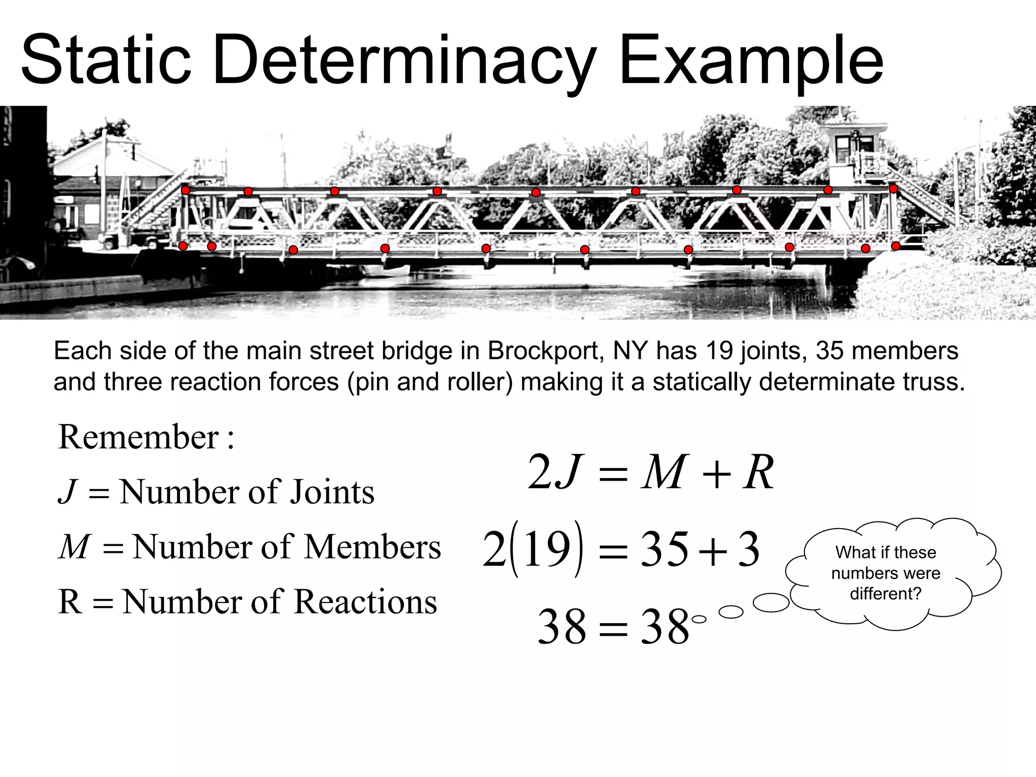

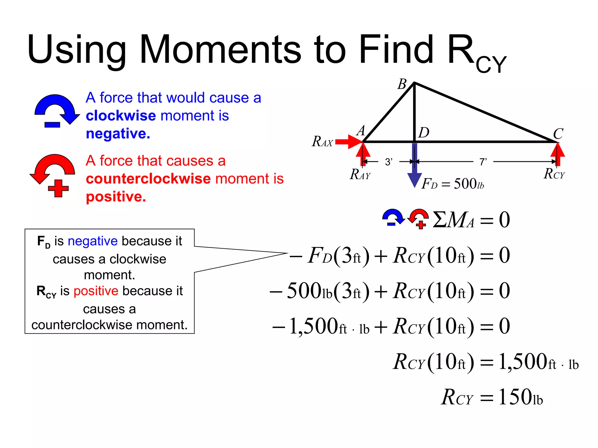
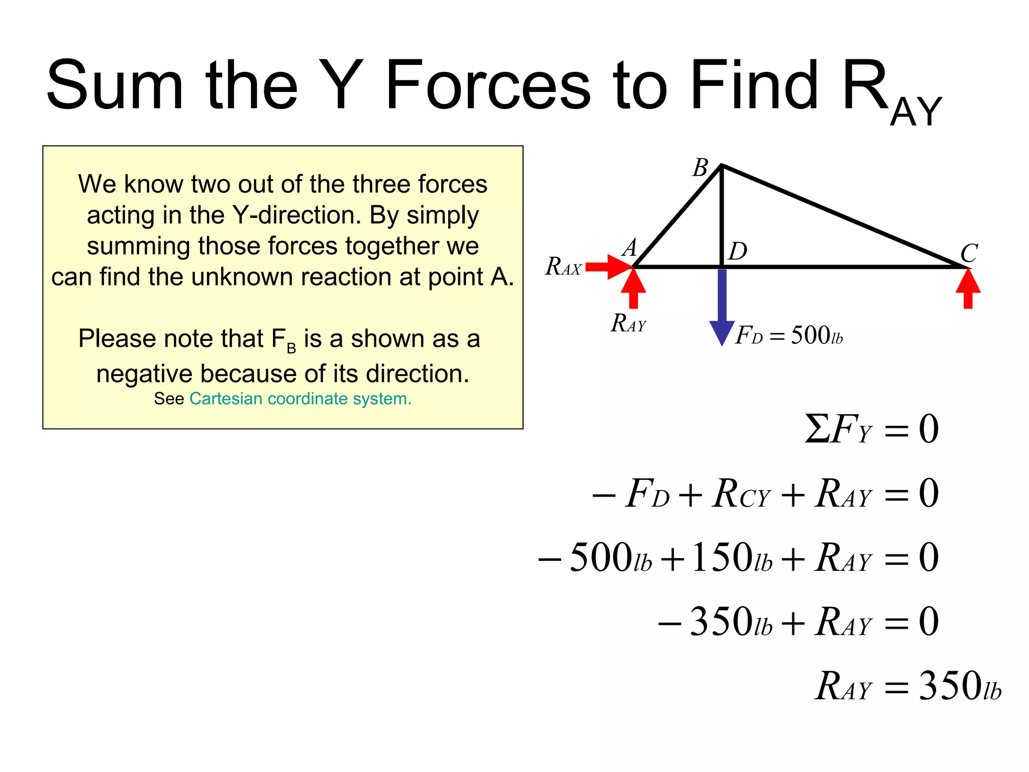
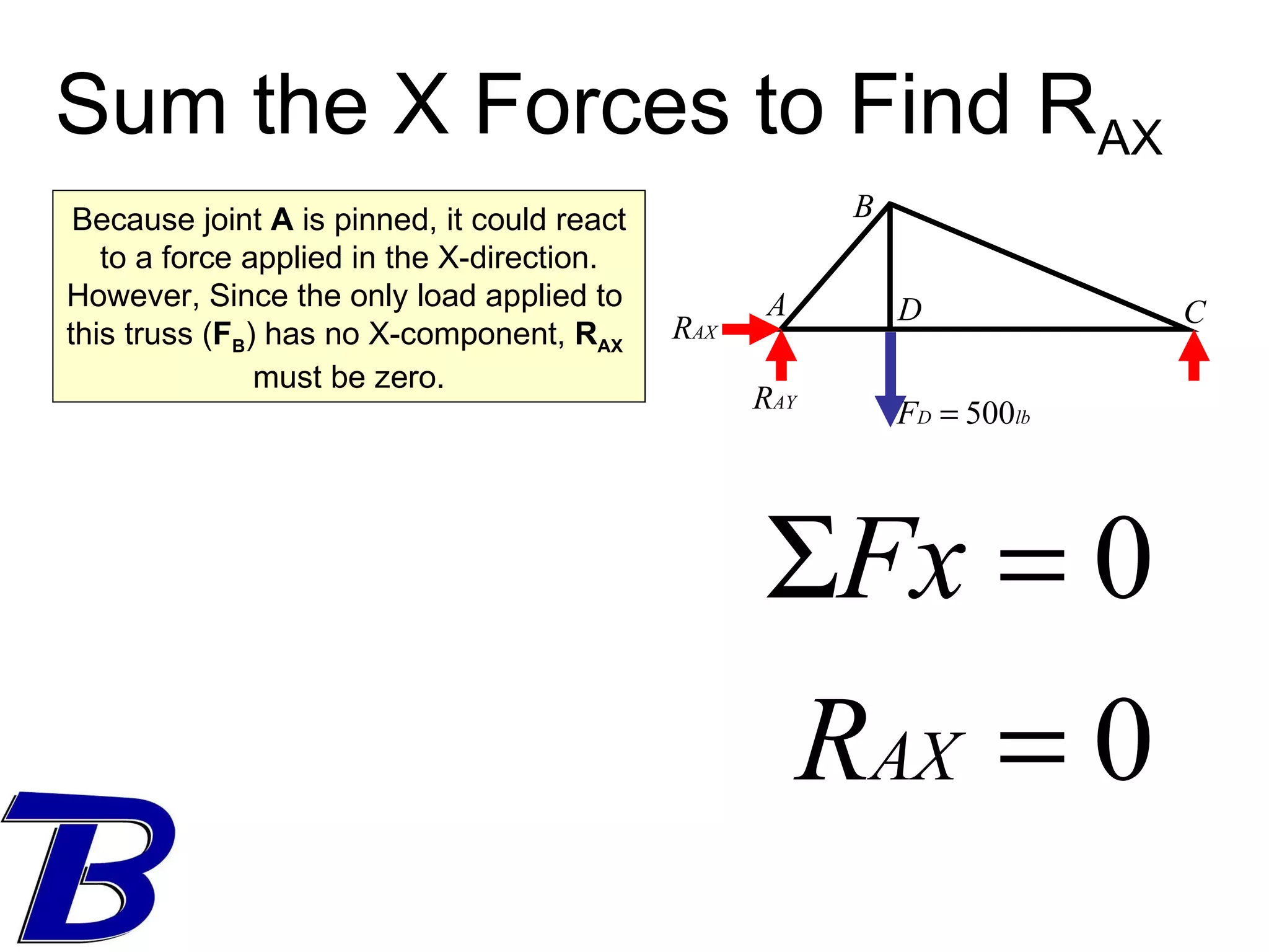
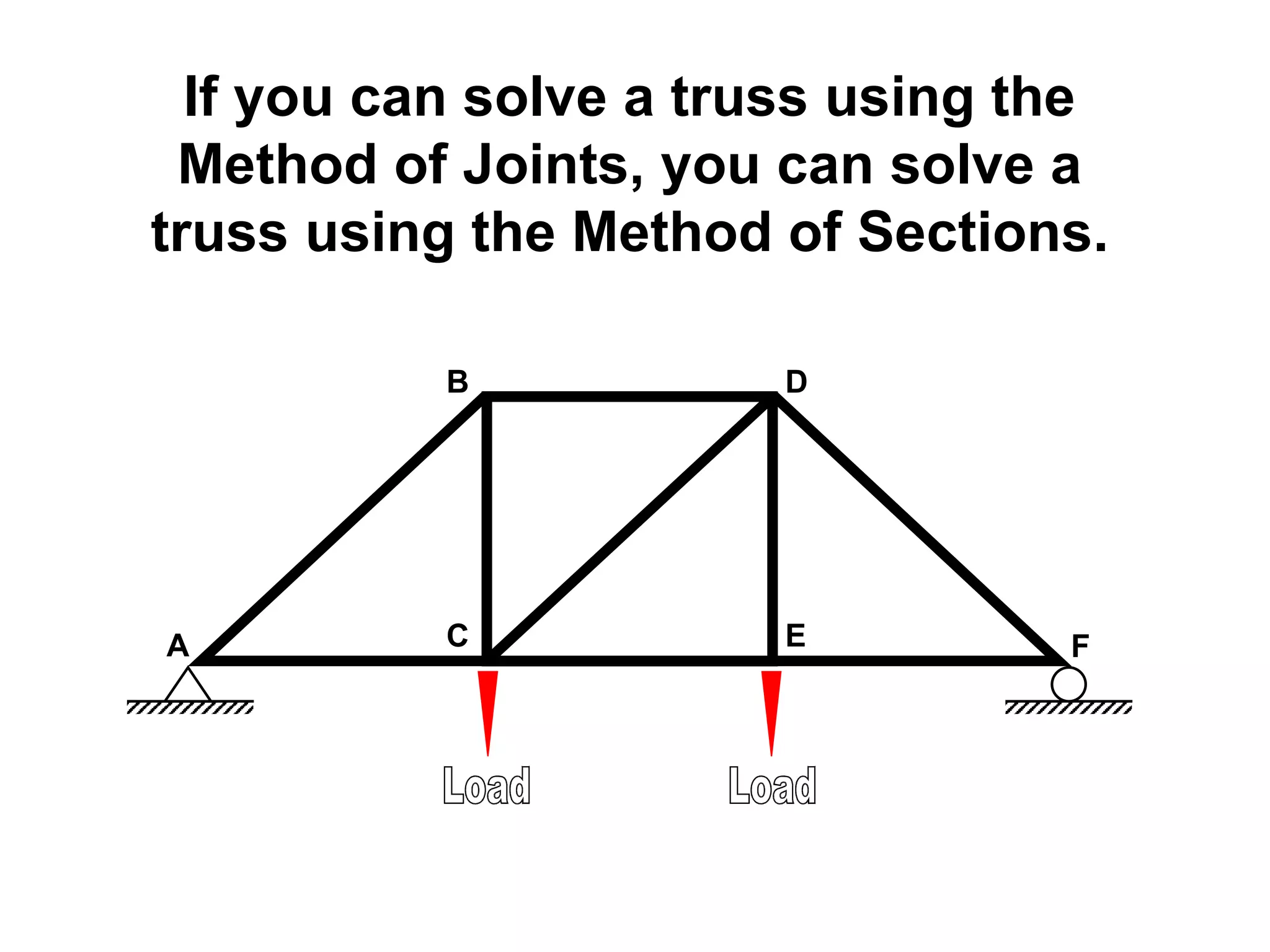
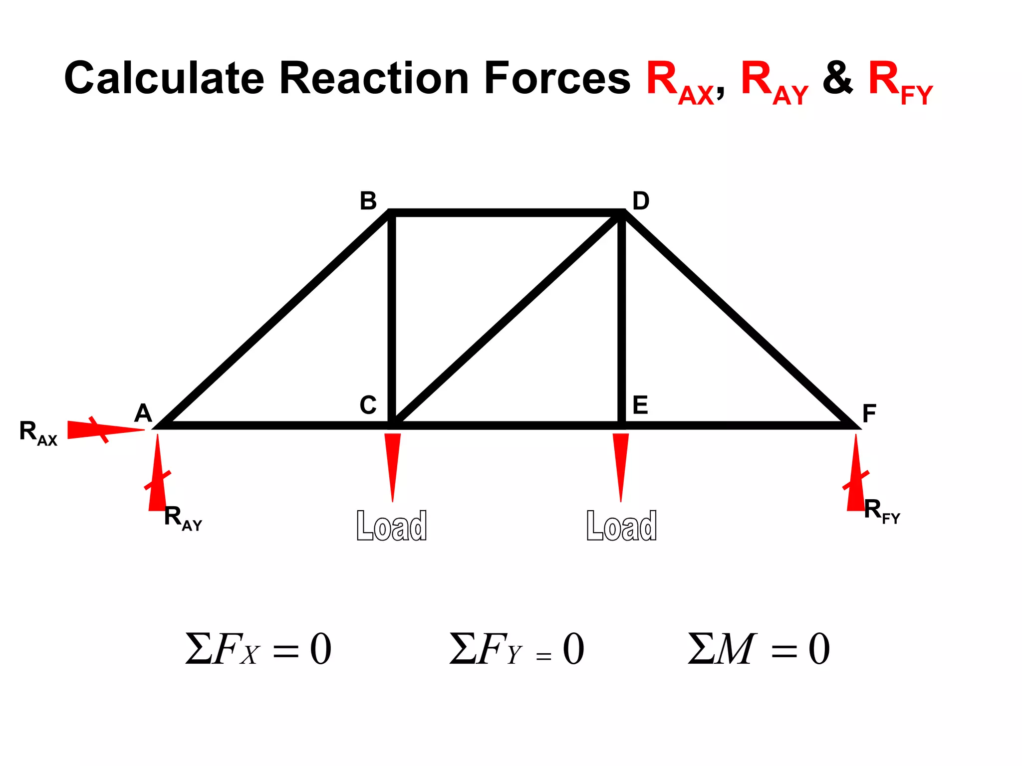
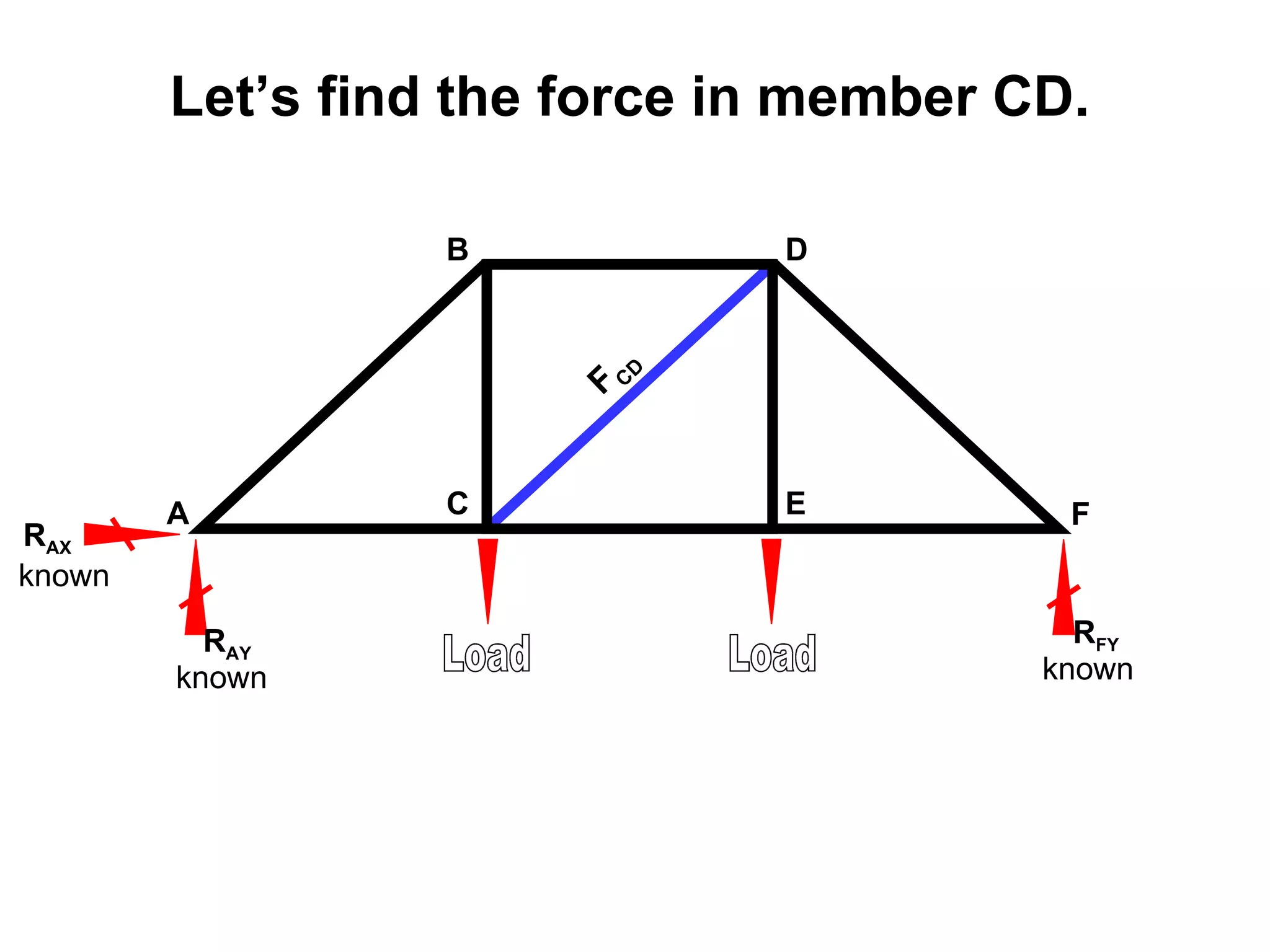
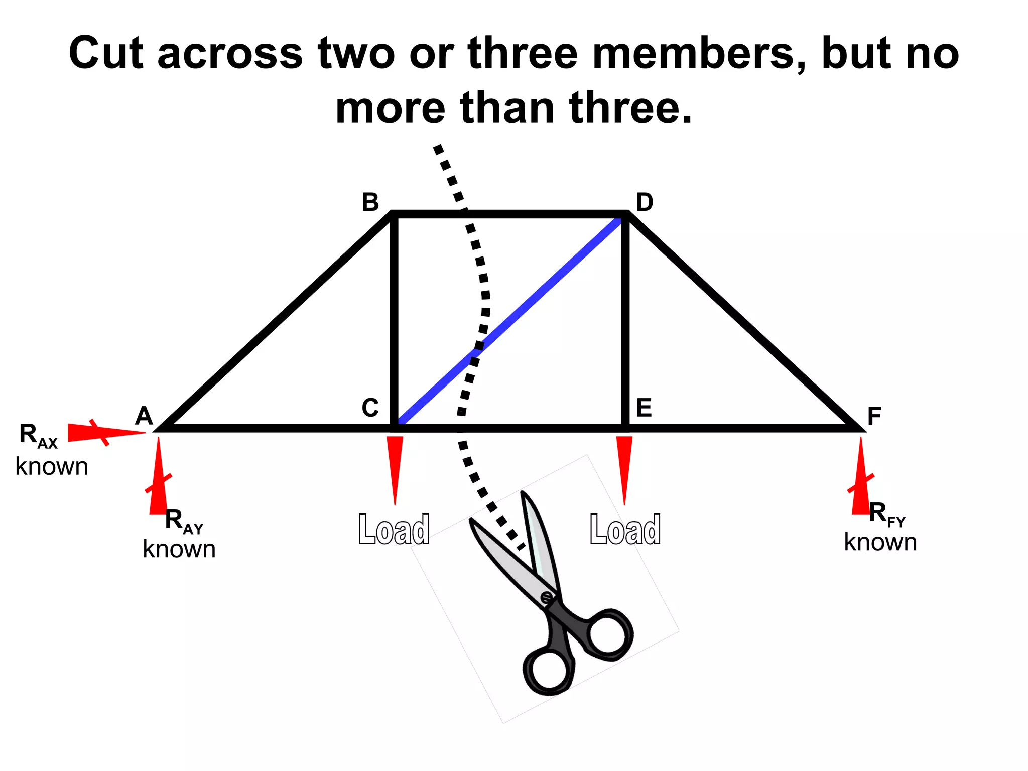
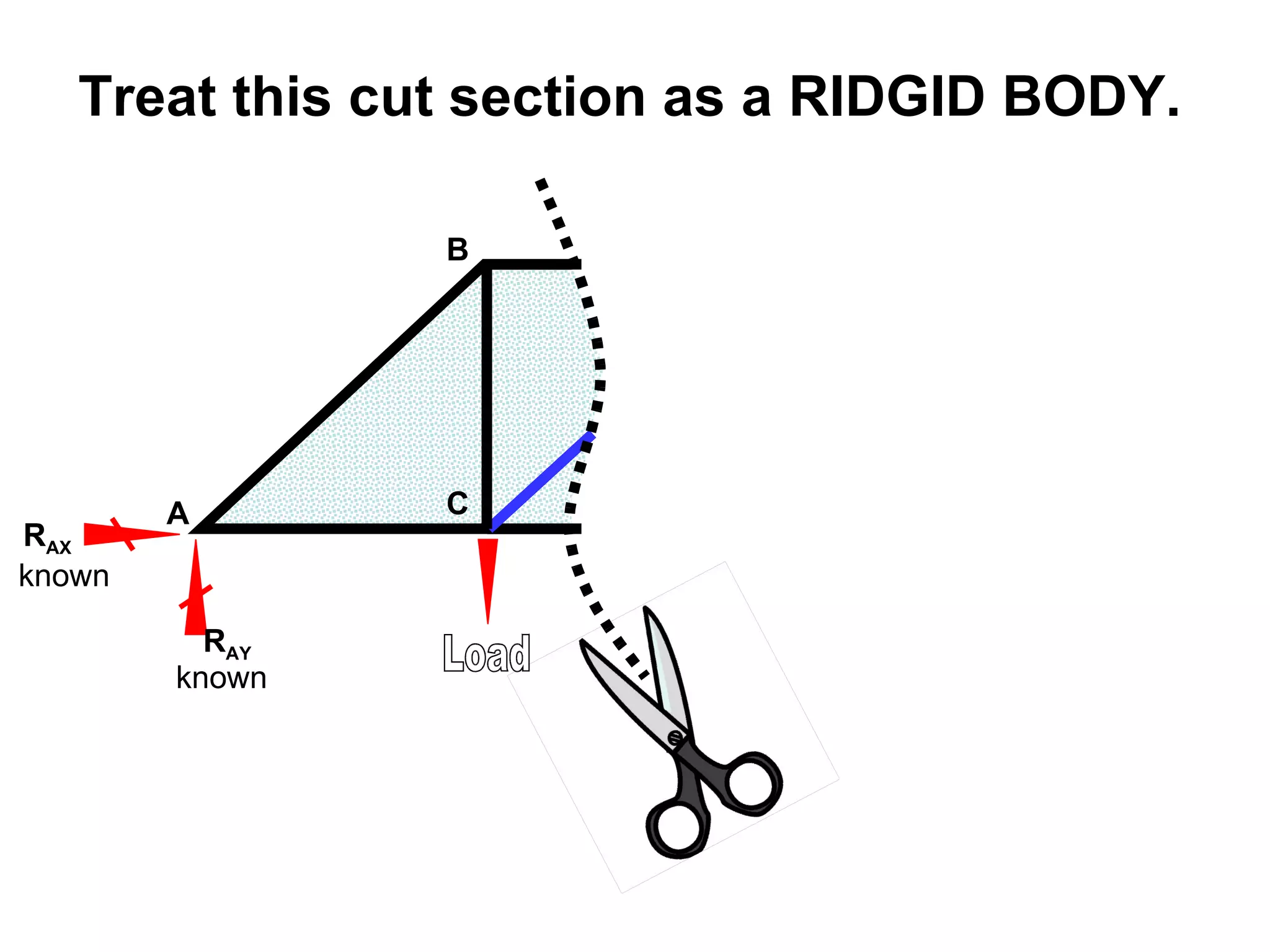
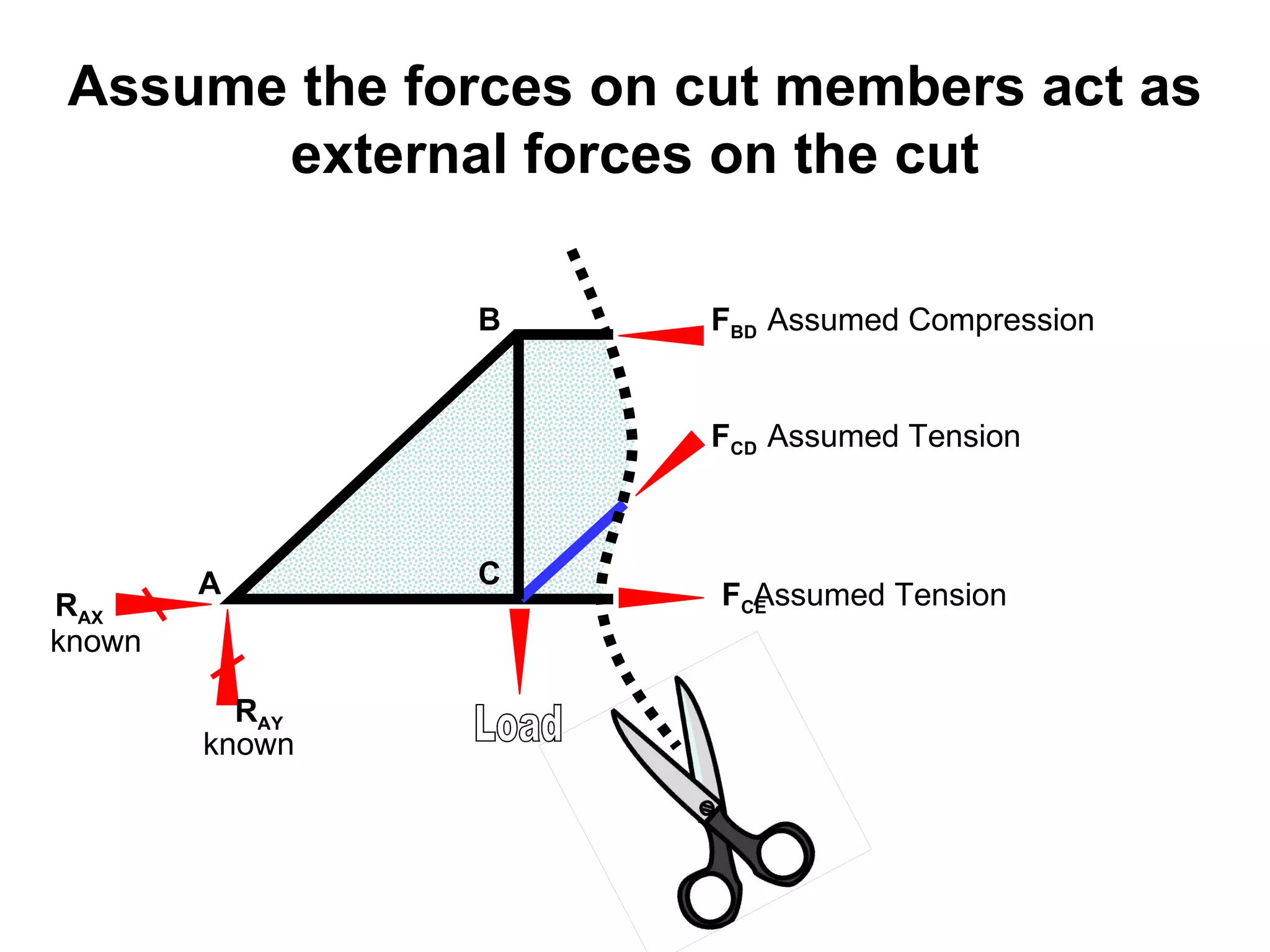
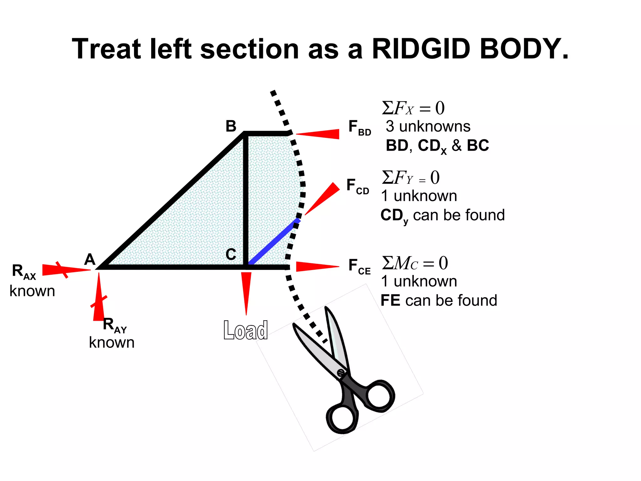
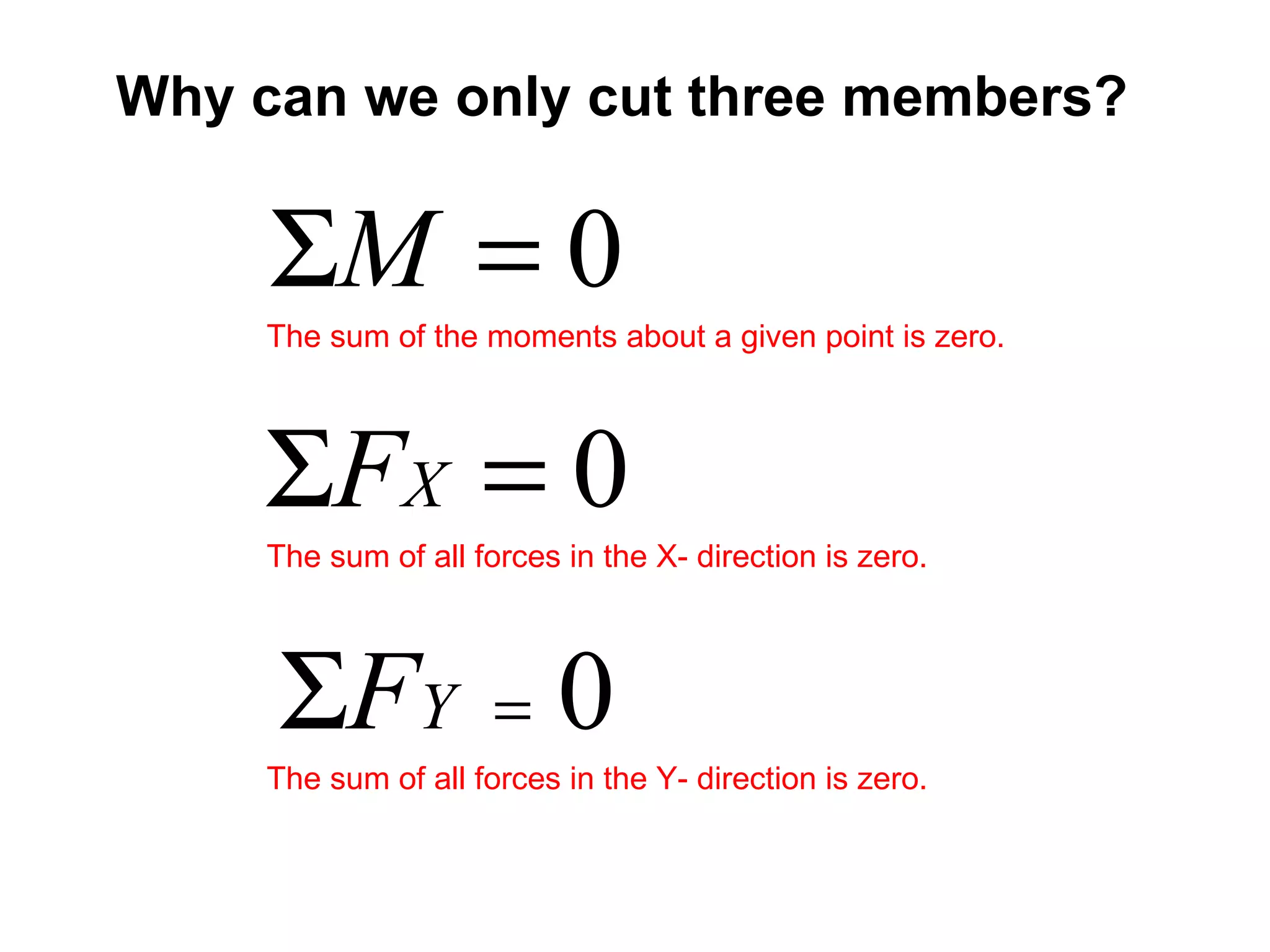
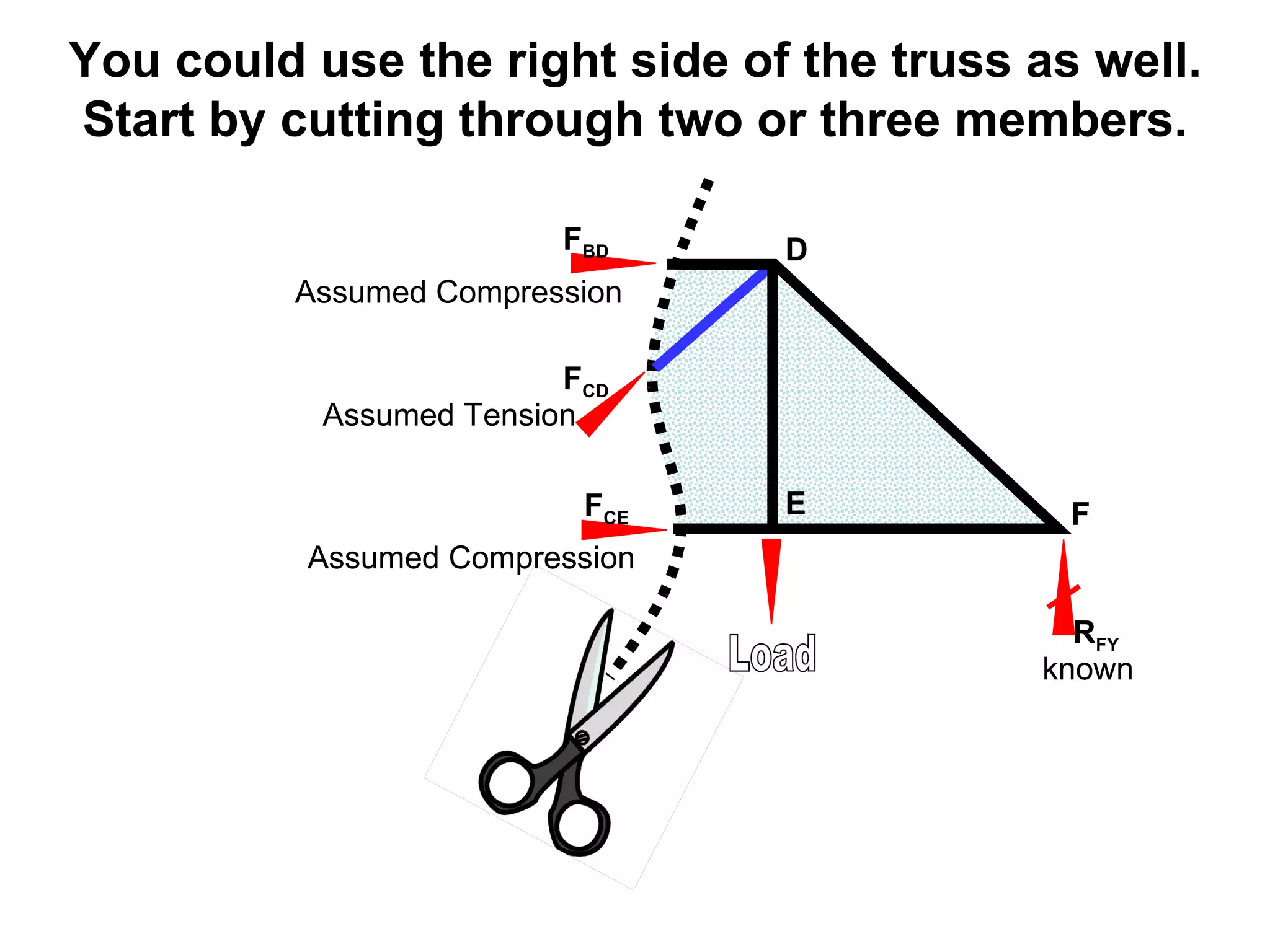
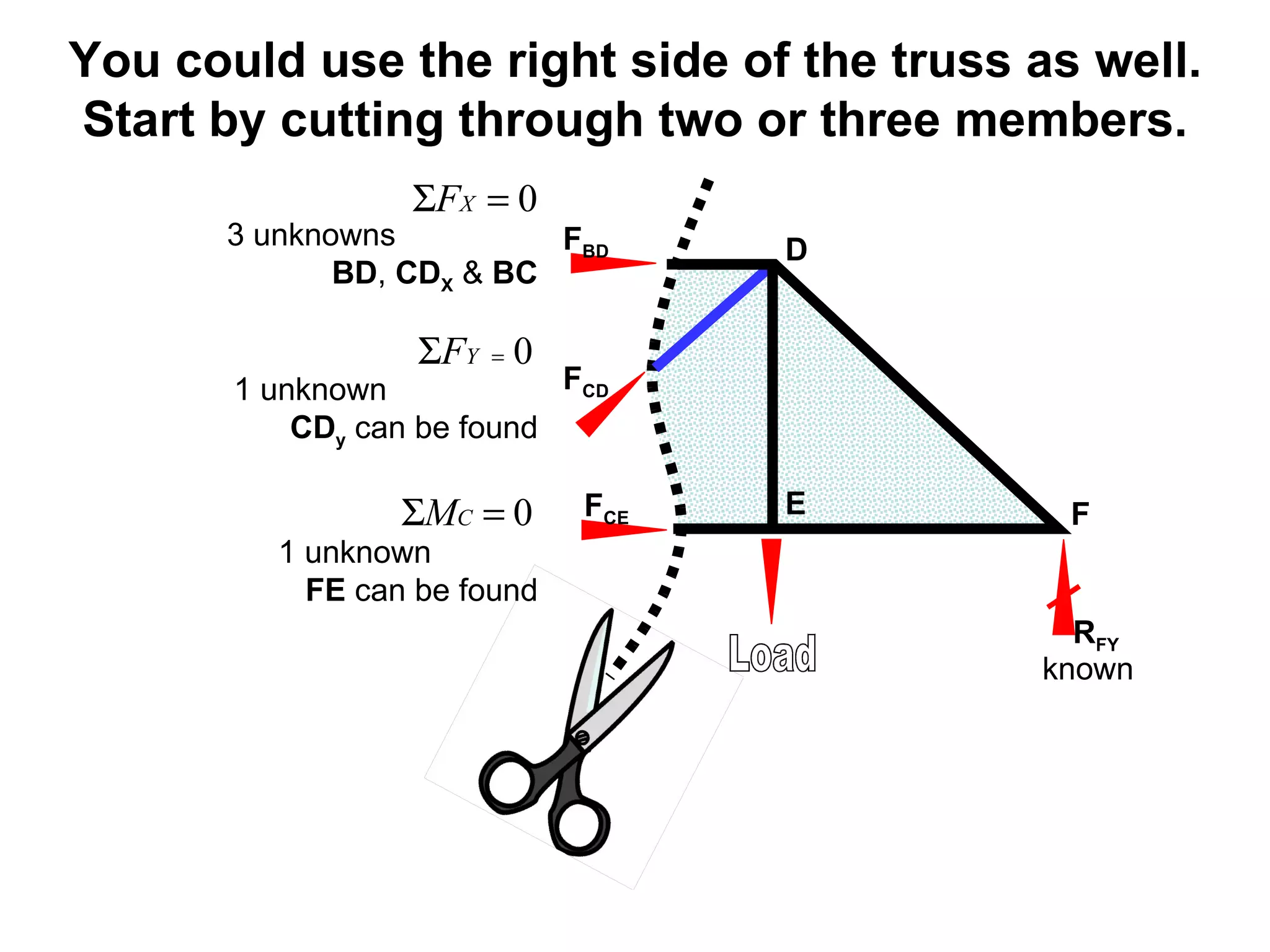


The document discusses methods for analyzing statically determinate truss structures, including the Method of Joints and Method of Sections. It uses the example of a truss bridge in Brockport, NY to demonstrate these methods. The Method of Sections involves cutting the truss into rigid bodies and applying equilibrium equations to solve for member forces. Reactions can first be found using the Method of Joints, then sections are cut to solve for internal forces.


