This document provides information about engineering mechanics and structural analysis. It includes:
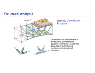
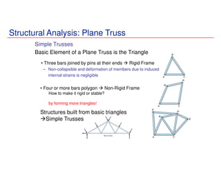
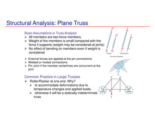
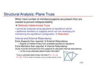
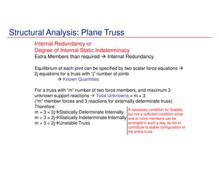
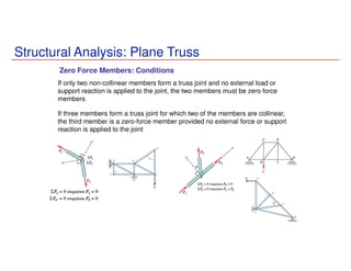
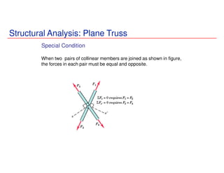
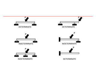
1) An overview of the concepts of equilibrium of rigid bodies, statically determinate and indeterminate structures, and the conditions for each.
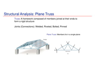
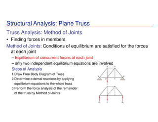
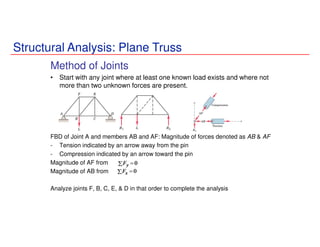
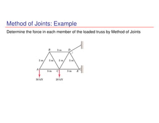
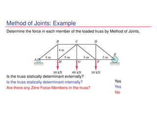
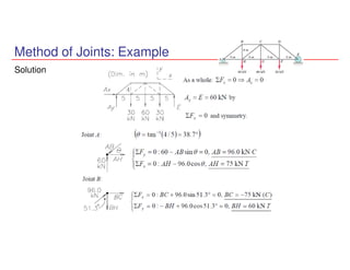
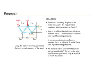
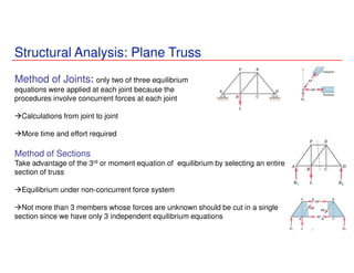
2) A description of the method of joints technique for analyzing plane trusses through applying equilibrium equations at each joint to determine member forces.
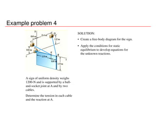
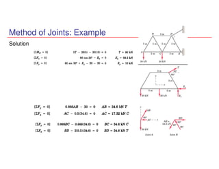
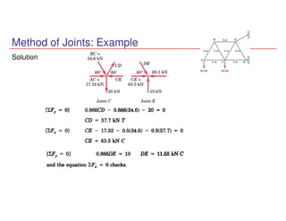
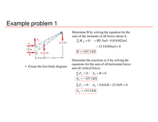
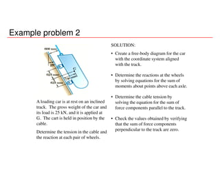
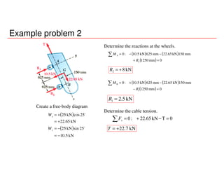
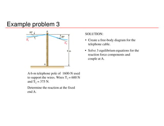
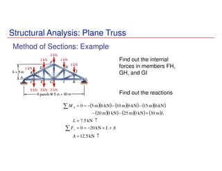
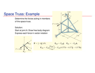
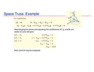
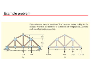
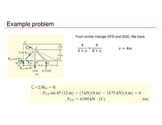
3) Worked examples that demonstrate applying the method of joints to solve for unknown member forces and reactions in various truss structures.
Truss is a framework, typically consisting of rafters, posts, and struts, supporting a roof, bridge, or other structure.
a truss is a structure that "consists of two-force members only, where the members are organized so that the assemblage as a whole behaves as a single object"
Concept of Particles and Free Body Diagram
Why FBD diagrams are used during the analysis?
It enables us to check the body for equilibrium.
By considering the FBD, we can clearly define the exact system of forces which we must use in the investigation of any constrained body.
It helps to identify the forces and ensures the correct use of equation of equilibrium.
Note:
Reactions on two contacting bodies are equal and opposite on account of Newton's III Law.
The type of reactions produced depends on the nature of contact between the bodies as well as that of the surfaces.
Sometimes it is necessary to consider internal free bodies such that the contacting surfaces lie within the given body. Such a free body needs to be analyzed when the body is deformable.
Physical Meaning of Equilibrium and its essence in Structural Application
The state of rest (in appropriate inertial frame) of a system particles and/or rigid bodies is called equilibrium.
A particle is said to be in equilibrium if it is in rest. A rigid body is said to be in equilibrium if the constituent particles contained on it are in equilibrium.
The rigid body in equilibrium means the body is stable.
Equilibrium means net force and net moment acting on the body is zero.
Essence in Structural Engineering
To find the unknown parameters such as reaction forces and moments induced by the body.
In Structural Engineering, the major problem is to identify the external reactions, internal forces and stresses on the body which are produced during the loading. For the identification of such parameters, we should assume a body in equilibrium. This assumption provides the necessary equations to determine the unknown parameters.
For the equilibrium body, the number of unknown parameters must be equal to number of available parameters provided by static equilibrium condition.
Mathematics for the Trades A Guided Approach Canadian 2nd Edition Carman Test...JudithLandrys
Full download : https://alibabadownload.com/product/mathematics-for-the-trades-a-guided-approach-canadian-2nd-edition-carman-test-bank/ Mathematics for the Trades A Guided Approach Canadian 2nd Edition Carman Test Bank
Lecture slides on the calculation of the bending stress in case of unsymmetrical bending. The Mohr's circle is used to determine the principal second moments of area.
Welcome to WIPAC Monthly the magazine brought to you by the LinkedIn Group Water Industry Process Automation & Control.
In this month's edition, along with this month's industry news to celebrate the 13 years since the group was created we have articles including
A case study of the used of Advanced Process Control at the Wastewater Treatment works at Lleida in Spain
A look back on an article on smart wastewater networks in order to see how the industry has measured up in the interim around the adoption of Digital Transformation in the Water Industry.
Saudi Arabia stands as a titan in the global energy landscape, renowned for its abundant oil and gas resources. It's the largest exporter of petroleum and holds some of the world's most significant reserves. Let's delve into the top 10 oil and gas projects shaping Saudi Arabia's energy future in 2024.
NO1 Uk best vashikaran specialist in delhi vashikaran baba near me online vas...Amil Baba Dawood bangali
Contact with Dawood Bhai Just call on +92322-6382012 and we'll help you. We'll solve all your problems within 12 to 24 hours and with 101% guarantee and with astrology systematic. If you want to take any personal or professional advice then also you can call us on +92322-6382012 , ONLINE LOVE PROBLEM & Other all types of Daily Life Problem's.Then CALL or WHATSAPP us on +92322-6382012 and Get all these problems solutions here by Amil Baba DAWOOD BANGALI
#vashikaranspecialist #astrologer #palmistry #amliyaat #taweez #manpasandshadi #horoscope #spiritual #lovelife #lovespell #marriagespell#aamilbabainpakistan #amilbabainkarachi #powerfullblackmagicspell #kalajadumantarspecialist #realamilbaba #AmilbabainPakistan #astrologerincanada #astrologerindubai #lovespellsmaster #kalajaduspecialist #lovespellsthatwork #aamilbabainlahore#blackmagicformarriage #aamilbaba #kalajadu #kalailam #taweez #wazifaexpert #jadumantar #vashikaranspecialist #astrologer #palmistry #amliyaat #taweez #manpasandshadi #horoscope #spiritual #lovelife #lovespell #marriagespell#aamilbabainpakistan #amilbabainkarachi #powerfullblackmagicspell #kalajadumantarspecialist #realamilbaba #AmilbabainPakistan #astrologerincanada #astrologerindubai #lovespellsmaster #kalajaduspecialist #lovespellsthatwork #aamilbabainlahore #blackmagicforlove #blackmagicformarriage #aamilbaba #kalajadu #kalailam #taweez #wazifaexpert #jadumantar #vashikaranspecialist #astrologer #palmistry #amliyaat #taweez #manpasandshadi #horoscope #spiritual #lovelife #lovespell #marriagespell#aamilbabainpakistan #amilbabainkarachi #powerfullblackmagicspell #kalajadumantarspecialist #realamilbaba #AmilbabainPakistan #astrologerincanada #astrologerindubai #lovespellsmaster #kalajaduspecialist #lovespellsthatwork #aamilbabainlahore #Amilbabainuk #amilbabainspain #amilbabaindubai #Amilbabainnorway #amilbabainkrachi #amilbabainlahore #amilbabaingujranwalan #amilbabainislamabad
Student information management system project report ii.pdfKamal Acharya
Our project explains about the student management. This project mainly explains the various actions related to student details. This project shows some ease in adding, editing and deleting the student details. It also provides a less time consuming process for viewing, adding, editing and deleting the marks of the students.
Sachpazis:Terzaghi Bearing Capacity Estimation in simple terms with Calculati...Dr.Costas Sachpazis
Terzaghi's soil bearing capacity theory, developed by Karl Terzaghi, is a fundamental principle in geotechnical engineering used to determine the bearing capacity of shallow foundations. This theory provides a method to calculate the ultimate bearing capacity of soil, which is the maximum load per unit area that the soil can support without undergoing shear failure. The Calculation HTML Code included.
We have compiled the most important slides from each speaker's presentation. This year’s compilation, available for free, captures the key insights and contributions shared during the DfMAy 2024 conference.
HEAP SORT ILLUSTRATED WITH HEAPIFY, BUILD HEAP FOR DYNAMIC ARRAYS.
Heap sort is a comparison-based sorting technique based on Binary Heap data structure. It is similar to the selection sort where we first find the minimum element and place the minimum element at the beginning. Repeat the same process for the remaining elements.
Hierarchical Digital Twin of a Naval Power SystemKerry Sado
A hierarchical digital twin of a Naval DC power system has been developed and experimentally verified. Similar to other state-of-the-art digital twins, this technology creates a digital replica of the physical system executed in real-time or faster, which can modify hardware controls. However, its advantage stems from distributing computational efforts by utilizing a hierarchical structure composed of lower-level digital twin blocks and a higher-level system digital twin. Each digital twin block is associated with a physical subsystem of the hardware and communicates with a singular system digital twin, which creates a system-level response. By extracting information from each level of the hierarchy, power system controls of the hardware were reconfigured autonomously. This hierarchical digital twin development offers several advantages over other digital twins, particularly in the field of naval power systems. The hierarchical structure allows for greater computational efficiency and scalability while the ability to autonomously reconfigure hardware controls offers increased flexibility and responsiveness. The hierarchical decomposition and models utilized were well aligned with the physical twin, as indicated by the maximum deviations between the developed digital twin hierarchy and the hardware.
NUMERICAL SIMULATIONS OF HEAT AND MASS TRANSFER IN CONDENSING HEAT EXCHANGERS...ssuser7dcef0
Power plants release a large amount of water vapor into the
atmosphere through the stack. The flue gas can be a potential
source for obtaining much needed cooling water for a power
plant. If a power plant could recover and reuse a portion of this
moisture, it could reduce its total cooling water intake
requirement. One of the most practical way to recover water
from flue gas is to use a condensing heat exchanger. The power
plant could also recover latent heat due to condensation as well
as sensible heat due to lowering the flue gas exit temperature.
Additionally, harmful acids released from the stack can be
reduced in a condensing heat exchanger by acid condensation. reduced in a condensing heat exchanger by acid condensation.
Condensation of vapors in flue gas is a complicated
phenomenon since heat and mass transfer of water vapor and
various acids simultaneously occur in the presence of noncondensable
gases such as nitrogen and oxygen. Design of a
condenser depends on the knowledge and understanding of the
heat and mass transfer processes. A computer program for
numerical simulations of water (H2O) and sulfuric acid (H2SO4)
condensation in a flue gas condensing heat exchanger was
developed using MATLAB. Governing equations based on
mass and energy balances for the system were derived to
predict variables such as flue gas exit temperature, cooling
water outlet temperature, mole fraction and condensation rates
of water and sulfuric acid vapors. The equations were solved
using an iterative solution technique with calculations of heat
and mass transfer coefficients and physical properties.
NUMERICAL SIMULATIONS OF HEAT AND MASS TRANSFER IN CONDENSING HEAT EXCHANGERS...
L04 5.pdf (trusses)
1. ME 101: Engineering Mechanics
Rajib Kumar Bhattacharjya
Department of Civil Engineering
Indian Institute of Technology Guwahati
M Block : Room No 005 : Tel: 2428
www.iitg.ernet.in/rkbc
2. Equilibrium of rigid body
∑ ∑ ∑ === 000 Ayx MFF
Equations of equilibrium become
There are three unknowns and number of
equation is three.
Therefore, the structure is statically
determinate
The rigid body is completely constrained
3. Equilibrium of rigid body
More unknowns than
equations
Fewer unknowns than
equations, partially
constrained
Equal number unknowns
and equations but
improperly constrained
4. Example problem 1
A fixed crane has a mass of 1000 kg
and is used to lift a 2400 kg crate. It
is held in place by a pin at A and a
rocker at B. The center of gravity of
the crane is located at G.
Determine the components of the
reactions at A and B.
SOLUTION:
• Create a free-body diagram for the crane.
• Determine B by solving the equation
for the sum of the moments of all forces
about A. Note there will be no
contribution from the unknown
reactions at A.
• Determine the reactions at A by
solving the equations for the sum of
all horizontal force components and
all vertical force components.
• Check the values obtained for the
reactions by verifying that the sum of
the moments about B of all forces is
zero.
5. Example problem 4
A sign of uniform density weighs
1200-N and is supported by a ball-
and-socket joint at A and by two
cables.
Determine the tension in each cable
and the reaction at A.
SOLUTION:
• Create a free-body diagram for the sign.
• Apply the conditions for static
equilibrium to develop equations for
the unknown reactions.
6. Example problem 4
• Create a free-body diagram for the
sign.
Since there are only 5 unknowns,
the sign is partially constrain. It is
free to rotate about the x axis. It is,
however, in equilibrium for the
given loading.
( )
( )kjiT
kji
T
rr
rr
TT
kjiT
kji
T
rr
rr
TT
EC
EC
EC
EC
ECEC
BD
BD
BD
BD
BDBD
rrr
rrr
rr
rrr
rrr
rrr
rr
rrr
285.0428.085.0
1.2
6.09.08.1
6.3
4.22.14.2
3
2
3
1
3
2
++−=
++−
=
−
−
=
−+−=
−+−
=
−
−
=
7. Example problem 4
• Apply the conditions for
static equilibrium to
develop equations for the
unknown reactions.
( )
( ) ( )
0m.N1440771.08.0:
0514.06.1:
0N1200m1.2
029.067.0:
0N120043.033.0:
086.067.0:
0N1200
=−+
=−
=−×+×+×=
=+−
=−++
=−−
=−++=
∑
∑
ECBD
ECBD
ECEBDBA
ECBDz
ECBDy
ECBDx
ECBD
TTk
TTj
jiTrTrM
TTAk
TTAj
TTAi
jTTAF
r
r
rrrrrrr
r
r
r
rrrrr
( ) ( ) ( )kjiA
TT ECBD
rrvr
N100.1N419N1502
N1402N451
−+=
==
Solve the 5 equations for the 5 unknowns,
8. Structural Analysis
Engineering Structure
An engineering structure is
any connected system of
members built to support or
transfer forces and to safely
withstand the loads applied
to it.
10. Structural Analysis: Plane Truss
Truss: A framework composed of members joined at their ends to
form a rigid structure
Joints (Connections): Welded, Riveted, Bolted, Pinned
Plane Truss: Members lie in a single plane
11. Structural Analysis: Plane Truss
Simple Trusses
Basic Element of a Plane Truss is the Triangle
• Three bars joined by pins at their ends Rigid Frame
– Non-collapsible and deformation of members due to induced
internal strains is negligible
• Four or more bars polygon Non-Rigid Frame
How to make it rigid or stable?
Structures built from basic triangles
Simple Trusses
by forming more triangles!
12. Structural Analysis: Plane Truss
Basic Assumptions in Truss Analysis
All members are two-force members.
Weight of the members is small compared with the
force it supports (weight may be considered at joints)
No effect of bending on members even if weight is
considered
External forces are applied at the pin connections
Welded or riveted connections
Pin Joint if the member centerlines are concurrent at the
joint
Common Practice in Large Trusses
Roller/Rocker at one end. Why?
to accommodate deformations due to
temperature changes and applied loads.
otherwise it will be a statically indeterminate
truss
13. Structural Analysis: Plane Truss
Truss Analysis: Method of Joints
• Finding forces in members
Method of Joints: Conditions of equilibrium are satisfied for the forces
at each joint
– Equilibrium of concurrent forces at each joint
– only two independent equilibrium equations are involved
Steps of Analysis
1.Draw Free Body Diagram of Truss
2.Determine external reactions by applying
equilibrium equations to the whole truss
3.Perform the force analysis of the remainder
of the truss by Method of Joints
14. Structural Analysis: Plane Truss
Method of Joints
• Start with any joint where at least one known load exists and where not
more than two unknown forces are present.
FBD of Joint A and members AB and AF: Magnitude of forces denoted as AB & AF
- Tension indicated by an arrow away from the pin
- Compression indicated by an arrow toward the pin
Magnitude of AF from
Magnitude of AB from
Analyze joints F, B, C, E, & D in that order to complete the analysis
15. Structural Analysis: Plane Truss
Method of Joints
• Negative force if assumed
sense is incorrect
Zero Force
Member
Check
Equilibrium
Show
forces on
members
16. Method of Joints: Example
Determine the force in each member of the loaded truss by Method of Joints
19. Structural Analysis: Plane Truss
When more number of members/supports are present than are
needed to prevent collapse/stability
Statically Indeterminate Truss
• cannot be analyzed using equations of equilibrium alone!
• additional members or supports which are not necessary for
maintaining the equilibrium configuration Redundant
Internal and External Redundancy
Extra Supports than required External Redundancy
– Degree of indeterminacy from available equilibrium equations
Extra Members than required Internal Redundancy
(truss must be removed from the supports to calculate internal redundancy)
– Is this truss statically determinate internally?
Truss is statically determinate internally if m + 3 = 2j
m = 2j – 3 m is number of members, and j is number of joints in truss
L06
20. Structural Analysis: Plane Truss
Internal Redundancy or
Degree of Internal Static Indeterminacy
Extra Members than required Internal Redundancy
Equilibrium of each joint can be specified by two scalar force equations
2j equations for a truss with “j” number of joints
Known Quantities
For a truss with “m” number of two force members, and maximum 3
unknown support reactions Total Unknowns = m + 3
(“m” member forces and 3 reactions for externally determinate truss)
Therefore:
m + 3 = 2j Statically Determinate Internally
m + 3 > 2j Statically Indeterminate Internally
m + 3 < 2j Unstable Truss
A necessary condition for Stability
but not a sufficient condition since
one or more members can be
arranged in such a way as not to
contribute to stable configuration of
the entire truss
21. Structural Analysis: Plane Truss
To maintain alignment of two members during construction
To increase stability during construction
To maintain stability during loading (Ex: to prevent buckling
of compression members)
To provide support if the applied loading is changed
To act as backup members in case some members fail or
require strengthening
Analysis is difficult but possible
Why to Provide Redundant Members?
24. Structural Analysis: Plane Truss
Zero Force Members: Conditions
If only two non-collinear members form a truss joint and no external load or
support reaction is applied to the joint, the two members must be zero force
members
If three members form a truss joint for which two of the members are collinear,
the third member is a zero-force member provided no external force or support
reaction is applied to the joint
25. Structural Analysis: Plane Truss
Special Condition
When two pairs of collinear members are joined as shown in figure,
the forces in each pair must be equal and opposite.
26. Method of Joints: Example
Determine the force in each member of the loaded truss by Method of Joints.
Is the truss statically determinant externally?
Is the truss statically determinant internally?
Are there any Zero Force Members in the truss?
Yes
Yes
No
30. Example problem 1
• Create the free-body diagram.
Determine B by solving the equation for the
sum of the moments of all forces about A.
( ) ( )
( ) 0m6kN5.23
m2kN81.9m5.1:0
=−
−∑ += BM A
kN1.107+=B
Determine the reactions at A by solving the
equations for the sum of all horizontal forces
and all vertical forces.
0:0 =+=∑ BAF xx
kN1.107−=xA
0kN5.23kN81.9:0 =−−=∑ yy AF
kN3.33+=yA
31. Example problem 2
A loading car is at rest on an inclined
track. The gross weight of the car and
its load is 25 kN, and it is applied at
G. The cart is held in position by the
cable.
Determine the tension in the cable and
the reaction at each pair of wheels.
SOLUTION:
• Create a free-body diagram for the car
with the coordinate system aligned
with the track.
• Determine the reactions at the wheels
by solving equations for the sum of
moments about points above each axle.
• Determine the cable tension by
solving the equation for the sum of
force components parallel to the track.
• Check the values obtained by verifying
that the sum of force components
perpendicular to the track are zero.
32. Example problem 2
Create a free-body diagram
( )
( )
kN10.5
25sinkN25
kN22.65
25coskN25
−=
−=
+=
+=
o
o
y
x
W
W
Determine the reactions at the wheels.
( ) ( )
( ) 0mm1250
mm150kN22.65mm625kN10.5:0
2 =+
−−=∑
R
M A
kN82 +=R
( ) ( )
( ) 0mm1250
mm150kN22.65mm625kN10.5:0
1 =−
−+=∑
R
MB
kN2.51 =R
Determine the cable tension.
0TkN22.65:0 =−+=∑ xF
kN22.7+=T
33. Example problem 3
A 6-m telephone pole of 1600-N used
to support the wires. Wires T1 = 600 N
and T2 = 375 N.
Determine the reaction at the fixed
end A.
SOLUTION:
• Create a free-body diagram for the
telephone cable.
• Solve 3 equilibrium equations for the
reaction force components and
couple at A.
34. Example problem 3
• Create a free-body diagram for
the frame and cable.
• Solve 3 equilibrium equations for the
reaction force components and couple.
010cos)N600(20cos)N375(:0 =°−°+=∑ xx AF
N238.50+=xA
( ) ( ) 020sinN37510sin600NN1600:0 =°−°−−=∑ yy AF
N1832.45+=yA
∑ = :0AM ( ) ( )
0(6m)
20cos375N)6(10cos600N
=
°−°+ mM A
N.m00.1431+=AM
35. Example
Using the method of joints, determine
the force in each member of the truss.
SOLUTION:
• Based on a free-body diagram of the
entire truss, solve the 3 equilibrium
equations for the reactions at E and C.
• Joint A is subjected to only two unknown
member forces. Determine these from the
joint equilibrium requirements.
• In succession, determine unknown
member forces at joints D, B, and E from
joint equilibrium requirements.
• All member forces and support reactions
are known at joint C. However, the joint
equilibrium requirements may be applied
to check the results.
36. Example
SOLUTION:
• Based on a free-body diagram of the entire truss,
solve the 3 equilibrium equations for the reactions
at E and C.
( )( ) ( )( ) ( )m3m6kN5m12kN10
0
E
M C
−+=
=∑
↑= kN50E
∑ == xx CF 0 0=xC
∑ ++−== yy CF kN50kN5-kN100
↓= kN35yC
37. Example
• Joint A is subjected to only two unknown
member forces. Determine these from the
joint equilibrium requirements.
534
kN10 ADAB FF
== CF
TF
AD
AB
kN5.12
kN5.7
=
=
• There are now only two unknown member
forces at joint D.
( ) DADE
DADB
FF
FF
5
32=
=
CF
TF
DE
DB
kN15
kN5.12
=
=
38. Example
• There are now only two unknown member
forces at joint B. Assume both are in tension.
( )
kN75.18
kN12kN50 5
4
5
4
−=
−−−==∑
BE
BEy
F
FF
CFBE kN75.18=
( ) ( )
kN25.26
75.18kN5.12kN5.70 5
3
5
3
+=
−−−==∑
BC
BCx
F
FF
TFBC kN25.26=
• There is one unknown member force at joint
E. Assume the member is in tension.
( )
kN75.43
kN75.18kN150 5
3
5
3
−=
++==∑
EC
ECx
F
FF
CFEC kN75.43=
39. Example
• All member forces and support reactions are
known at joint C. However, the joint equilibrium
requirements may be applied to check the results.
( ) ( )
( ) ( )checks075.4335
checks075.4325.26
5
4
5
3
=+−=
=+−=
∑
∑
y
x
F
F
41. Structural Analysis: Plane Truss
Method of Joints: only two of three equilibrium
equations were applied at each joint because the
procedures involve concurrent forces at each joint
Calculations from joint to joint
More time and effort required
Method of Sections
Take advantage of the 3rd or moment equation of equilibrium by selecting an entire
section of truss
Equilibrium under non-concurrent force system
Not more than 3 members whose forces are unknown should be cut in a single
section since we have only 3 independent equilibrium equations
42. Structural Analysis: Plane Truss
Method of Sections
Find out the reactions from equilibrium of whole truss
To find force in member BE
Cut an imaginary section (dotted line)
Each side of the truss section should remain in
equilibrium
For calculating force on member EF, take moment
about B
Now apply ∑ ܨ௬ = 0 to obtain forces on the members BE
Take moment about E, for calculating force BC
43. Structural Analysis: Plane Truss
Method of Sections
• Principle: If a body is in equilibrium, then any part of the body is also in
equilibrium.
• Forces in few particular member can be directly found out quickly without solving
each joint of the truss sequentially
• Method of Sections and Method of Joints can be conveniently combined
• A section need not be straight.
• More than one section can be used to solve a given problem
44. ( )( ) ( )( ) ( )( )
( )( ) ( )( ) ( )
↑=
++−==
↑=
+−−
−−−==
∑
∑
kN5.12
kN200
kN5.7
m30kN1m25kN1m20
kN6m15kN6m10kN6m50
A
ALF
L
L
M
y
A
Find out the internal
forces in members FH,
GH, and GI
Find out the reactions
Structural Analysis: Plane Truss
Method of Sections: Example
45. • Pass a section through members FH, GH, and
GI and take the right-hand section as a free
body.
( )( ) ( )( ) ( )
kN13.13
0m33.5m5kN1m10kN7.50
0
+=
=−−
=∑
GI
GI
H
F
F
M
• Apply the conditions for static equilibrium to determine the
desired member forces.
TFGI kN13.13=
Method of Sections: Example Solution
°==== 07.285333.0
m15
m8
tan αα
GL
FG
46. ( )( ) ( )( ) ( )( )
( )( )
kN82.13
0m8cos
m5kN1m10kN1m15kN7.5
0
−=
=+
−−
=∑
FH
FH
G
F
F
M
α
CFFH kN82.13=
( )
( )( ) ( )( ) ( )( )
kN371.1
0m15cosm5kN1m10kN1
0
15.439375.0
m8
m5
tan
3
2
−=
=++
=
°====
∑
GH
GH
L
F
F
M
HI
GI
β
ββ
CFGH kN371.1=
Method of Sections: Example Solution
47. Structural Analysis: Space Truss
Space Truss
L07
3-D counterpart of the Plane Truss
Idealized Space Truss Rigid links
connected at their ends by ball and
socket joints
48. Structural Analysis: Space Truss
Space Truss
6 bars joined at their ends to form the edges of a tetrahedron
as the basic non-collapsible unit.
3 additional concurrent bars whose ends are attached to
three joints on the existing structure are required to add a
new rigid unit to extend the structure.
If center lines of joined members intersect at a point
Two force members assumption is justified
Each member under Compression or Tension
A space truss formed in this way is called
a Simple Space Truss
49. A necessary condition for Stability but not a
sufficient condition since one or more members
can be arranged in such a way as not to
contribute to stable configuration of the entire
truss
Structural Analysis: Space Truss
Static Determinacy of Space Truss
Six equilibrium equations available to find out support reactions
If these are sufficient to determine all support reactions
The space truss is Statically Determinate Externally
Equilibrium of each joint can be specified by three scalar force equations
3j equations for a truss with “j” number of joints
Known Quantities
For a truss with “m” number of two force members, and maximum 6 unknown support
reactions Total Unknowns = m + 6
(“m” member forces and 6 reactions for externally determinate truss)
Therefore:
m + 6 = 3j Statically Determinate Internally
m + 6 > 3j Statically Indeterminate Internally
m + 6 < 3j Unstable Truss
50. Structural Analysis: Space Truss
Method of Joints
- If forces in all members are required
- Solve the 3 scalar equilibrium equations at each joint
- Solution of simultaneous equations may be avoided if a joint having at least one known force &
at most three unknown forces is analysed first
- Use Cartesian vector analysis if the 3-D geometry is complex (∑F=0)
Method of Sections
- If forces in only few members are required
- Solve the 6 scalar equilibrium equations in each cut part of truss
- Section should not pass through more than 6 members whose forces are unknown
- Cartesian vector analysis (∑F=0, ∑M=0)
51. Space Truss: Example
Determine the forces acting in members
of the space truss.
Solution:
Start at joint A: Draw free body diagram
Express each force in vector notation
52. Space Truss: Example
Rearranging the terms and equating the coefficients of i, j, and k unit
vector to zero will give:
Next Joint B may be analysed.
53. Space Truss: Example
Using Scalar equations of equilibrium at joints D and C will give:
Joint B: Draw the Free Body Diagram
Scalar equations of equilibrium may be used at joint B