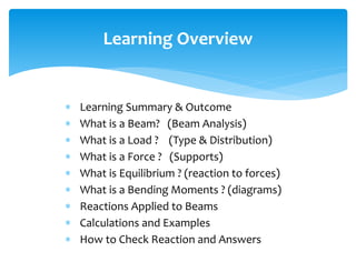
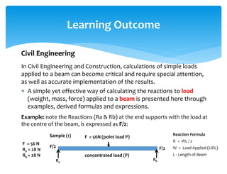
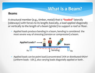
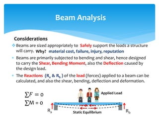
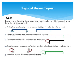
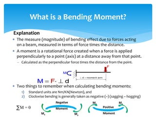
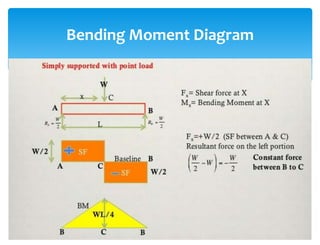
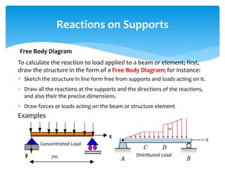
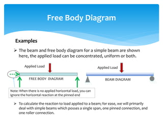
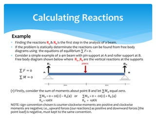
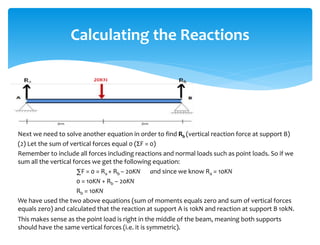
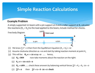
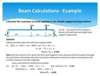
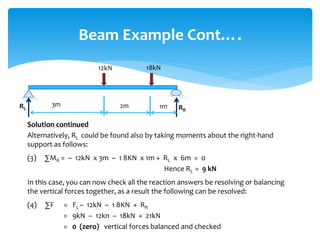
Mechanical Principles
and Applications
Reactions and Loads
Applied to Beams
Dr Andrew Kimmance
PhD; MSc, BSc-Eng, MCIOB, MAPM, MAHEA
 Learning Summary & Outcome
 What is a Beam? (Beam Analysis)
 What is a Load ? (Type & Distribution)
 What is a Force ? (Supports)
 What is Equilibrium ? (reaction to forces)
 What is a Bending Moments ? (diagrams)
 Reactions Applied to Beams
 Calculations and Examples
 How to Check Reaction and Answers
Learning Overview
Before starting to calculate the reactions to
loads applied to a beam we first need to
understand the mechanisms involved ; e.g.,
how, when, where, who, why, and what we
are going to calculate
Learning Summary
Why is this important?
In Civil Engineering and Construction, calculations of simple loads
applied to a beam can become critical and require special attention,
as well as accurate implementation of the results.
 A simple yet effective way of calculating the reactions to load
(weight, mass, force) applied to a beam is presented here through
examples, derived formulas and expressions.
Example: note the Reactions (Ra & Rb) at the end supports with the load at
the centre of the beam, is expressed as F/2:
Learning Outcome
Civil Engineering
F = 56 N
Ra = 28 N
Rb = 28 N
F = 56N (point load P)
F/2 F/2
concentrated load (P)
Sample (1)
RbRa
Reaction Formula
R = WL / 2
W = Load Applied (UDL)
L - Length of Beam
What is a Beam?
A structural member (e.g., timber, metal) that is “loaded” laterally
(sideways) with forces to its length; basically, a load applied diagonally
or vertically to the length of a beam (girder) to support a roof or floor.
 Applied loads produce bending in a beam, bending is considered the
most severe way of stressing (tension or compression) a beam.
 Applied loads can be point load (concentrated ) KN or distributed KN/m²
(uniform loads - UDL), also varying loads diagonally applied or both .
Beams
Applied Loads F
Beam
bendingRa Rb
Beams are sized appropriately to support the loads a structure
will carry.
 Beams are primarily subjected to bending and shear, hence designed
to carry the Shear, Bending Moment, also the Deflection caused by
the design load.
 The Reactions (Ra & Rb ) of the load (forces) applied to a beam can be
calculated, and also the shear, bending, deflection and deformation.
Beam Analysis
Why?
Safely
∑𝐹 = 0
∑M = 0
material cost, failure, injury, reputation
Ra RbStatic Equilibrium
Applied Load
Considerations
Beams come in many shapes and sizes and can be classified according to
how they are supported.
1. A simple or overhanging beam are supported by a pinned and a roller support.
2. Continuous beams are supported over several supports
3. Cantilever beams have a moment fixed at one end
4. Fixed beams are supported by fixed connections at both end and have end moments
5. Propped- Fixed at one end supported at other
Typical Beam Types
Types
Beams
Failure
 A Load (structural) or action is a Force, deformation, or acceleration
applied to a structure or its components.
 Loads cause stresses, deformations, and displacements, and excess
loads or overloading may cause structural failure.
 Types of Load include, dead and live loads (gravity & lateral):
– Dead loads are static forces that are relatively constant for a
lengthy time, such as weight of the structure and roof.
– Live (dynamic) loads or imposed loads, usually unstable or moving
loads, such as temporary, transition or impact.
What other loads do we need to consider?
What is a Load?
Lateral, wind, show
Loads Explained
 The loads (dead, live, wind, snow) are
initially applied to a building surface
(floor or roof)
 Transferred through walls, floors and
beams which then transfer the load to
other building component.
 The beams in a building transfer the
load to the structural components
that supports its ends which may be a
girder as indicated by the arrows.
How are Load Distributed?
 A Force is considered the action of one body on another and is
usually characterised by three vector (trajectory) quantities:
1) Point of application (point load)
2) Magnitude (size of load)
3) Direction (bearing or path of load)
 In order to design a beam, the magnitude of the reaction forces (Ra +
Rb) need to be calculated to achieve static equilibrium.
 Reaction forces are linear or rotational.
– A linear reaction is often called a shear reaction (F or R)
– A rotational reaction is often called a moment reaction (M)
 Reaction forces indicate type and magnitude of the forces that are
transferred and “must balance” the applied forces ∑ 𝐹= 0.
What is a Force?
Forces Explained
 At a roller support, beams can rotate at the support and, in this
case, move horizontally and can only react with a single linear
reaction force in the direction of the support.
 A pin connection will hold the beam stationary both vertically and
horizontally but will allow the beam to rotate. This results in
horizontal (Fx) and vertical (y) linear reaction forces from the
support, but no rotational reaction.
 A fixed support will not allow the beam to move in any way. The
resulting reaction forces include a horizontal force (Fx), a vertical
force (Fy), and a moment reaction, M.
 Important Note: No matter what support is used, the resulting
forces must be remain static (stationary) and be in equilibrium.
Forces and Supports
Supports Explained
Forces and Supports
 The state of a beam or object in which the load, weight or force
counteract each other so that the beam remains stationary.
 A bean can move when a load or force is applied, thus must be in
static equilibrium to successfully carry loads.
 In order to be static, a beam must be in equilibrium, all of the forces
or loads acting on the beam must counteract and balance each other.
What is Equilibrium?
Static Equilibrium
Note: What come
down or across must
be equal to what
goes up and across
Applied Forces
Applied Loads
zero
 The loads applied to the beam (from a roof or floor) must be
resisted by forces from the beam supports to be static.
 These resisting forces are called “Reaction Forces”.
Reaction Forces in Equilibrium
Reaction Forces
∑ 𝐹 = 0
50KN
Applied Point Load
Reaction
Force
Reaction
Force
R1 R2
25KN 25KN
Static Equilibrium
Length of beam (m)
Reaction Formula
R = WL / 2
W = Load Applied (UDL)
L - Length of Beam
 The sum of all vertical forces (F) acting on a
body (beam) must equal zero.
 The sum of all horizontal forces (F) acting on
a body (beam) must equal zero.
 The sum of all moments (about any point)
acting on a body (beam) must equal zero.
Fundamental Principles of Equilibrium
 yF 0
 xF 0
 pM 0
∑ F = Zero: where
Note: A moment is created when a force tends to rotate an object. It is
equal to the force times the perpendicular distance to the force.
 The measure (magnitude) of bending effect due to forces acting
on a beam, measured in terms of force times the distance.
 A moment is a rotational force created when a force is applied
perpendicularly to a point (axis) at a distance away from that point.
– Calculated as the perpendicular force times the distance from the point.
 Two things to remember when calculating bending moments:
1) Standard units are Nm/KN(Newton), and
2) Clockwise bending is generally taken as negative (–) (sagging – hogging)
What is a Bending Moment?
∑M = 0
Explanation
Mx My
Positive
MomentMy
Mx
Negative
Moment
Bending Moment Diagram
To calculate the reaction to load applied to a beam or element; first,
draw the structure in the form of a Free Body Diagram; for instance:
 Sketch the structure in line form free from supports and loads acting on it.
 Draw all the reactions at the supports and the directions of the reactions,
and also their the precise dimensions.
 Draw forces or loads acting on the beam or structure element
Examples
Reactions on Supports
Free Body Diagram
Concentrated Load
Distributed Load7m
Free Body Diagram
 The beam and free body diagram for a simple beam are shown
here, the applied load can be concentrated, uniform or both.
 To calculate the reaction to load applied to a beam; for ease, we will primarily
deal with simple beams which posses a single span, one pinned connection, and
one roller connection.
FREE BODY DIAGRAM
Applied Load
Note: When there is no applied horizontal load, you can
ignore the horizontal reaction at the pinned end
Applied Load
BEAM DIAGRAM
Examples
 Finding the reactions Ra & Rb is the first step in the analysis of a beam.
 If the problem is statically determinate the reactions can be found from free body
diagrams using the equations of equilibrium ∑ 𝐹= 0.
 Consider a simple example of a 4m beam with pin support at A and roller support at B.
Free body diagram shown below where Ra +Rb are the vertical reactions at the supports
(1) Firstly, consider the sum of moments about point B and let ∑𝑀B equal zero.
∑MB = 0 = 20(2) – RA(4) or ∑MA = 0 = -20(2) + RB (4)
RA = 10KN RB = 10KN
NOTE: sign convention chosen is counter-clockwise moments are positive and clockwise
moments are negative; i.e., upward forces (our reactions) as positive and downward forces (the
point load) is negative, must kept to the same convention.
Calculating Reactions
Example
∑ 𝐹 = 0
∑ 𝑀 = 0
Next we need to solve another equation in order to find Rb (vertical reaction force at support B)
(2) Let the sum of vertical forces equal 0 (ΣF = 0)
Remember to include all forces including reactions and normal loads such as point loads. So if we
sum all the vertical forces we get the following equation:
∑F = 0 = Ra + Rb – 20KN and since we know Ra = 10KN
0 = 10KN + Rb – 20KN
Rb = 10KN
We have used the two above equations (sum of moments equals zero and sum of vertical forces
equals zero) and calculated that the reaction at support A is 10kN and reaction at support B 10kN.
This makes sense as the point load is right in the middle of the beam, meaning both supports
should have the same vertical forces (i.e. it is symmetric).
Calculating the Reactions
A simply supported 1m beam with a pin support at A and a roller support at B, calculate
the reactions (Ra + Rb) to the load applied to the beam, include method for checks.
Simple Reaction Calculations
Example Problem
Point Load
20KN
Rb
Ra
o.6m0.4m
(1) We know ∑ 𝐹 = 0 then from the Equilibrium Equation (Ra + Rb) = 20
(2) Assume clockwise direction as +ve and start by taking reaction moment at point Ra
(3) This will be: -Rb x 1 + 20 x 0.4 = 0 …. hence,
(4) Rb = 8KN now take moments about the reaction on the right:
(5) Ra x 1 + 20 x 0.6 = 0
(6) Ra = 12KN ….. check these answers by balancing vertical forces ∑F = Ra + Rb- 20 = 0
(7) ∑F = 0 then ∑F = 12 + 8 - 20 = 0 check
Free body Diagram
A B
Calculate the reactions to loads applied to the simple supported beam below:
Solution
Taking moments about the left-hand support yields
(1) ∑ML= 0 = 12kN x 3m + 18KN x 5m – RR x 6m = 0
6 + 90 – RR x 6 = 0
Hence RR = 21 kN
Note that the moment of RL about the left=hand support is zero, because the force passes through
the point there. Remember also that convention clockwise moments are taken to be positive and
counter clockwise moments negative.
Now, summation of vertical forces yields:
(2) ∑F = RL – 12kN – 1 8KN + RR x = 0 But we know RR = 21 kN
Therefore, R L – 12kN – 18KN + 21kN = 0
Hence RL = 9 kN
Beam Calculations - Example
12kN 18kN
2m3m 1mRL RR
Let (RL + RR) stand for the reactions
forces at the left-hand and right-hand
support respectively
Solution continued
Alternatively, RL could be found also by taking moments about the right-hand
support as follows:
(3) ∑MR = – 12kN x 3m – 1 8KN x 1m + RL x 6m = 0
Hence RL = 9 kN
In this case, you can now check all the reaction answers be resolving or balancing
the vertical forces together, as a result the following can be resolved:
(4) ∑F = FL – 12kN – 1 8KN + RR
= 9kN – 12kn – 18kN + 21kN
= 0 (zero) vertical forces balanced and checked
Beam Example Cont….
12kN 18kN
2m3m 1mRL RR
 Understand of Beams and Applied Loads
 Understanding of Reactions and Moments
 How to calculate the reaction to loads applied to a beam
 Questions
 Thank you
Question on Leaning Outcome

Mechanical principles and applications pres

  • 1.
    Mechanical Principles and Applications Reactionsand Loads Applied to Beams Dr Andrew Kimmance PhD; MSc, BSc-Eng, MCIOB, MAPM, MAHEA
  • 2.
     Learning Summary& Outcome  What is a Beam? (Beam Analysis)  What is a Load ? (Type & Distribution)  What is a Force ? (Supports)  What is Equilibrium ? (reaction to forces)  What is a Bending Moments ? (diagrams)  Reactions Applied to Beams  Calculations and Examples  How to Check Reaction and Answers Learning Overview
  • 3.
    Before starting tocalculate the reactions to loads applied to a beam we first need to understand the mechanisms involved ; e.g., how, when, where, who, why, and what we are going to calculate Learning Summary Why is this important?
  • 4.
    In Civil Engineeringand Construction, calculations of simple loads applied to a beam can become critical and require special attention, as well as accurate implementation of the results.  A simple yet effective way of calculating the reactions to load (weight, mass, force) applied to a beam is presented here through examples, derived formulas and expressions. Example: note the Reactions (Ra & Rb) at the end supports with the load at the centre of the beam, is expressed as F/2: Learning Outcome Civil Engineering F = 56 N Ra = 28 N Rb = 28 N F = 56N (point load P) F/2 F/2 concentrated load (P) Sample (1) RbRa Reaction Formula R = WL / 2 W = Load Applied (UDL) L - Length of Beam
  • 5.
    What is aBeam? A structural member (e.g., timber, metal) that is “loaded” laterally (sideways) with forces to its length; basically, a load applied diagonally or vertically to the length of a beam (girder) to support a roof or floor.  Applied loads produce bending in a beam, bending is considered the most severe way of stressing (tension or compression) a beam.  Applied loads can be point load (concentrated ) KN or distributed KN/m² (uniform loads - UDL), also varying loads diagonally applied or both . Beams Applied Loads F Beam bendingRa Rb
  • 6.
    Beams are sizedappropriately to support the loads a structure will carry.  Beams are primarily subjected to bending and shear, hence designed to carry the Shear, Bending Moment, also the Deflection caused by the design load.  The Reactions (Ra & Rb ) of the load (forces) applied to a beam can be calculated, and also the shear, bending, deflection and deformation. Beam Analysis Why? Safely ∑𝐹 = 0 ∑M = 0 material cost, failure, injury, reputation Ra RbStatic Equilibrium Applied Load Considerations
  • 7.
    Beams come inmany shapes and sizes and can be classified according to how they are supported. 1. A simple or overhanging beam are supported by a pinned and a roller support. 2. Continuous beams are supported over several supports 3. Cantilever beams have a moment fixed at one end 4. Fixed beams are supported by fixed connections at both end and have end moments 5. Propped- Fixed at one end supported at other Typical Beam Types Types
  • 8.
  • 9.
     A Load(structural) or action is a Force, deformation, or acceleration applied to a structure or its components.  Loads cause stresses, deformations, and displacements, and excess loads or overloading may cause structural failure.  Types of Load include, dead and live loads (gravity & lateral): – Dead loads are static forces that are relatively constant for a lengthy time, such as weight of the structure and roof. – Live (dynamic) loads or imposed loads, usually unstable or moving loads, such as temporary, transition or impact. What other loads do we need to consider? What is a Load? Lateral, wind, show Loads Explained
  • 10.
     The loads(dead, live, wind, snow) are initially applied to a building surface (floor or roof)  Transferred through walls, floors and beams which then transfer the load to other building component.  The beams in a building transfer the load to the structural components that supports its ends which may be a girder as indicated by the arrows. How are Load Distributed?
  • 11.
     A Forceis considered the action of one body on another and is usually characterised by three vector (trajectory) quantities: 1) Point of application (point load) 2) Magnitude (size of load) 3) Direction (bearing or path of load)  In order to design a beam, the magnitude of the reaction forces (Ra + Rb) need to be calculated to achieve static equilibrium.  Reaction forces are linear or rotational. – A linear reaction is often called a shear reaction (F or R) – A rotational reaction is often called a moment reaction (M)  Reaction forces indicate type and magnitude of the forces that are transferred and “must balance” the applied forces ∑ 𝐹= 0. What is a Force? Forces Explained
  • 12.
     At aroller support, beams can rotate at the support and, in this case, move horizontally and can only react with a single linear reaction force in the direction of the support.  A pin connection will hold the beam stationary both vertically and horizontally but will allow the beam to rotate. This results in horizontal (Fx) and vertical (y) linear reaction forces from the support, but no rotational reaction.  A fixed support will not allow the beam to move in any way. The resulting reaction forces include a horizontal force (Fx), a vertical force (Fy), and a moment reaction, M.  Important Note: No matter what support is used, the resulting forces must be remain static (stationary) and be in equilibrium. Forces and Supports Supports Explained
  • 13.
  • 14.
     The stateof a beam or object in which the load, weight or force counteract each other so that the beam remains stationary.  A bean can move when a load or force is applied, thus must be in static equilibrium to successfully carry loads.  In order to be static, a beam must be in equilibrium, all of the forces or loads acting on the beam must counteract and balance each other. What is Equilibrium? Static Equilibrium Note: What come down or across must be equal to what goes up and across Applied Forces Applied Loads zero
  • 15.
     The loadsapplied to the beam (from a roof or floor) must be resisted by forces from the beam supports to be static.  These resisting forces are called “Reaction Forces”. Reaction Forces in Equilibrium Reaction Forces ∑ 𝐹 = 0 50KN Applied Point Load Reaction Force Reaction Force R1 R2 25KN 25KN Static Equilibrium Length of beam (m) Reaction Formula R = WL / 2 W = Load Applied (UDL) L - Length of Beam
  • 16.
     The sumof all vertical forces (F) acting on a body (beam) must equal zero.  The sum of all horizontal forces (F) acting on a body (beam) must equal zero.  The sum of all moments (about any point) acting on a body (beam) must equal zero. Fundamental Principles of Equilibrium  yF 0  xF 0  pM 0 ∑ F = Zero: where Note: A moment is created when a force tends to rotate an object. It is equal to the force times the perpendicular distance to the force.
  • 17.
     The measure(magnitude) of bending effect due to forces acting on a beam, measured in terms of force times the distance.  A moment is a rotational force created when a force is applied perpendicularly to a point (axis) at a distance away from that point. – Calculated as the perpendicular force times the distance from the point.  Two things to remember when calculating bending moments: 1) Standard units are Nm/KN(Newton), and 2) Clockwise bending is generally taken as negative (–) (sagging – hogging) What is a Bending Moment? ∑M = 0 Explanation Mx My Positive MomentMy Mx Negative Moment
  • 18.
  • 19.
    To calculate thereaction to load applied to a beam or element; first, draw the structure in the form of a Free Body Diagram; for instance:  Sketch the structure in line form free from supports and loads acting on it.  Draw all the reactions at the supports and the directions of the reactions, and also their the precise dimensions.  Draw forces or loads acting on the beam or structure element Examples Reactions on Supports Free Body Diagram Concentrated Load Distributed Load7m
  • 20.
    Free Body Diagram The beam and free body diagram for a simple beam are shown here, the applied load can be concentrated, uniform or both.  To calculate the reaction to load applied to a beam; for ease, we will primarily deal with simple beams which posses a single span, one pinned connection, and one roller connection. FREE BODY DIAGRAM Applied Load Note: When there is no applied horizontal load, you can ignore the horizontal reaction at the pinned end Applied Load BEAM DIAGRAM Examples
  • 21.
     Finding thereactions Ra & Rb is the first step in the analysis of a beam.  If the problem is statically determinate the reactions can be found from free body diagrams using the equations of equilibrium ∑ 𝐹= 0.  Consider a simple example of a 4m beam with pin support at A and roller support at B. Free body diagram shown below where Ra +Rb are the vertical reactions at the supports (1) Firstly, consider the sum of moments about point B and let ∑𝑀B equal zero. ∑MB = 0 = 20(2) – RA(4) or ∑MA = 0 = -20(2) + RB (4) RA = 10KN RB = 10KN NOTE: sign convention chosen is counter-clockwise moments are positive and clockwise moments are negative; i.e., upward forces (our reactions) as positive and downward forces (the point load) is negative, must kept to the same convention. Calculating Reactions Example ∑ 𝐹 = 0 ∑ 𝑀 = 0
  • 22.
    Next we needto solve another equation in order to find Rb (vertical reaction force at support B) (2) Let the sum of vertical forces equal 0 (ΣF = 0) Remember to include all forces including reactions and normal loads such as point loads. So if we sum all the vertical forces we get the following equation: ∑F = 0 = Ra + Rb – 20KN and since we know Ra = 10KN 0 = 10KN + Rb – 20KN Rb = 10KN We have used the two above equations (sum of moments equals zero and sum of vertical forces equals zero) and calculated that the reaction at support A is 10kN and reaction at support B 10kN. This makes sense as the point load is right in the middle of the beam, meaning both supports should have the same vertical forces (i.e. it is symmetric). Calculating the Reactions
  • 23.
    A simply supported1m beam with a pin support at A and a roller support at B, calculate the reactions (Ra + Rb) to the load applied to the beam, include method for checks. Simple Reaction Calculations Example Problem Point Load 20KN Rb Ra o.6m0.4m (1) We know ∑ 𝐹 = 0 then from the Equilibrium Equation (Ra + Rb) = 20 (2) Assume clockwise direction as +ve and start by taking reaction moment at point Ra (3) This will be: -Rb x 1 + 20 x 0.4 = 0 …. hence, (4) Rb = 8KN now take moments about the reaction on the right: (5) Ra x 1 + 20 x 0.6 = 0 (6) Ra = 12KN ….. check these answers by balancing vertical forces ∑F = Ra + Rb- 20 = 0 (7) ∑F = 0 then ∑F = 12 + 8 - 20 = 0 check Free body Diagram A B
  • 24.
    Calculate the reactionsto loads applied to the simple supported beam below: Solution Taking moments about the left-hand support yields (1) ∑ML= 0 = 12kN x 3m + 18KN x 5m – RR x 6m = 0 6 + 90 – RR x 6 = 0 Hence RR = 21 kN Note that the moment of RL about the left=hand support is zero, because the force passes through the point there. Remember also that convention clockwise moments are taken to be positive and counter clockwise moments negative. Now, summation of vertical forces yields: (2) ∑F = RL – 12kN – 1 8KN + RR x = 0 But we know RR = 21 kN Therefore, R L – 12kN – 18KN + 21kN = 0 Hence RL = 9 kN Beam Calculations - Example 12kN 18kN 2m3m 1mRL RR Let (RL + RR) stand for the reactions forces at the left-hand and right-hand support respectively
  • 25.
    Solution continued Alternatively, RLcould be found also by taking moments about the right-hand support as follows: (3) ∑MR = – 12kN x 3m – 1 8KN x 1m + RL x 6m = 0 Hence RL = 9 kN In this case, you can now check all the reaction answers be resolving or balancing the vertical forces together, as a result the following can be resolved: (4) ∑F = FL – 12kN – 1 8KN + RR = 9kN – 12kn – 18kN + 21kN = 0 (zero) vertical forces balanced and checked Beam Example Cont…. 12kN 18kN 2m3m 1mRL RR
  • 26.
     Understand ofBeams and Applied Loads  Understanding of Reactions and Moments  How to calculate the reaction to loads applied to a beam  Questions  Thank you Question on Leaning Outcome

Editor's Notes

  • #2 The fundamental relation between mass and weight is defined by Newton's Second Law, and can be expressed as: F = m a (1) where F = force (N, lbf) m = mass (kg, slugs) a = acceleration (m/s2, ft/s2)
  • #4 What is a beam, what are the loads, what is a force, what is a reaction and moment, SAFETY, design, and the beam can bend with forces applied. Failure – injury and reputation.
  • #5 A reaction force is the force applied to a beam when it rests against something. For simplicity, we are only going to examine and calculate the reaction to loads applied (acting) to a beam resting on simple supports, as shown in the diagram, and include checks by balancing the vertical forces. The load shown here is a point load concentrated and acting in the centre of the beam, thus the Reactions Ra & Rb at the end supports with the load at the centre of the beam are F/2:
  • #6 A long, sturdy piece of squared timber or metal used to support the roof or floor of a building. Typical types: joist, purlin, girder, spar, support, strut, stay, brace, scantling, batten, transom, lintel, stringer, baulk, board, timber, plank, lath, rafter; collar beam, tie beam, summer (tree), hammer beam, cantilever, pole, etc The students on the beam represent the load applied to the beam. The load is applied transversely, or perpendicularly, to the length of the beam, which produce bending, and bending is the most severe way of stressing a component
  • #7 Beams: A structural element that carries a load that is applied transverse (perpendicular) to its length. Usually a horizontal member that carries a vertical applied load. The top fibres of a beam are in compression; the bottom fibre's are in tension. Failure – injury and reputation.
  • #8 Beams come in many shapes and sizes and can be classified according to how they are supported. A simple beam is supported by a pinned and a roller support. A continuous beam is supported over several supports. A fixed beam is supported by a fixed connection at each end. A propped beam is fixed at one end and supported by a pin or roller at the other end. An overhang beam is similar to a simple beam except the beam extends over one of the supports.
  • #10 Structural loads or actions are forces, deformations, or accelerations applied to a structure or its components. Loads cause stresses, deformations, and displacements in structures. Assessment of their effects is carried out by the methods of structural analysis. Excess load or overloading may cause structural failure, and hence such possibility should be either considered in the design or strictly controlled.
  • #11 The load (dead, live, snow, wind, etc.) is initially applied to a building surface, such as a wall or a floor. The load is then transferred through that component (the wall or floor) to the nearest beams. The beams transfer the load to the structural components that supports its ends which may be a girder as indicated by the arrows. The beam can also transfer loads to a column or a load-bearing wall. The load continues to be transferred through structural components until it reaches the supporting soil. In this structural steel frame, a concentrated load is applied to an elevated floor. The floor transfers the load to adjacent beams. The beams carry the load to larger beams called girders. These girders will then transfer the load to the supporting columns, etc.
  • #12 In order to design a beam, we must calculate the magnitude of the reaction forces. The reaction forces will also indicate the types and magnitude of forces that will be transferred to the supporting members.
  • #13 For a beam in balance loaded with weights (or other load forces) the reactions forces - R - at the supports equals the load forces - F. The force balance can be expressed as F1 + F2 + .... + Fn = R1 + R2 (1) where F = force from load (N, lbf) R = force from support (N, lbf) In addition for a beam in balance the algebraic sum of moments equals zero. The moment balance can be expressed as F1 af1 + F2 af2 + .... + Fn afn = R ar1 + R ar2 (2) where a = the distance from the force to a common reference - usually the distance to one of the supports (m, ft)
  • #14 The method of support dictates the types of reaction forces from the supporting members. At a roller support, the beam can rotate at the support and, in this case, move horizontally. A roller support can only react with a single linear reaction force in the direction of the support. A pin connection will hold the beam stationary both vertically and horizontally but will allow the beam to rotate. This results in horizontal (Fx) and vertical (y) linear reaction forces from the support, but no rotational reaction. A fixed support will not allow the beam to move in any way. The resulting reaction forces include a horizontal force (Fx), a vertical force (Fy), and a moment reaction, M.
  • #15 Obviously we do not want the beams in a building to constantly move. Yes, the beam will deflect when a load is applied, but it will quickly return to a static condition – that is, it will stop moving. In order to be static, a beam must be in equilibrium – all of the forces acting on the beam must counteract and balance each other.
  • #17 In order for a beam to be in static equilibrium, the principles of equilibrium must hold true. A moment is created when a force tends to rotate and object. It is equal to the force times the perpendicular distance to the force. We will use these principles to calculate the beam reactions.
  • #18 A bending moment is the reaction induced in a structural element when an external force or moment is applied to the element causing the element to bend. The most common or simplest structural element subjected to bending moments is the beam. The bending moment at a section through a structural element may be defined as "the sum of the moments about that section of all external forces acting to one side of that section". The forces and moments on either side of the section must be equal in order to counteract each other and maintain a state of equilibrium so the same bending moment will result from summing the moments, regardless of which side of the section is selected. If clockwise bending moments are taken as negative, then a negative bending moment within an element will cause "sagging", and a positive moment will cause "hogging". It is therefore clear that a point of zero bending moment within a beam is a point of contraflexure—that is the point of transition from hogging to sagging or vice versa.
  • #21 In this class, we will primarily deal with simple beams which are beams that possess a single span, one pinned connection, and one roller connection. The beam diagram and free body diagram for a simple beam are shown here. The applied load can be concentrated, uniform, or a combination of both. A concentrated load is shown here. Since the horizontal reaction at the pinned connection will always be zero when there is no applied horizontal load, you may draw the free body diagram without the horizontal reaction.
  • #22 We have chosen point B to prove this can be done at either ends of the beam (provided it is pin supported). However you could just as easily work from point A. So, now we sum the moments about point B and let the sum equal 0: Signs clockwise +-ve as this is the most common sign convention but it is up to you. You must ALWAYS use the same sign convention throughout the whole problem. Always use the same sign convention from the start.