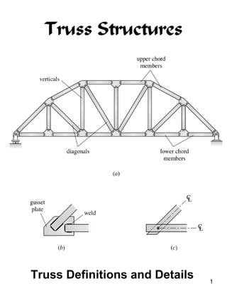
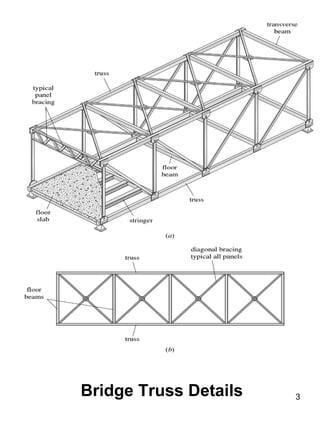
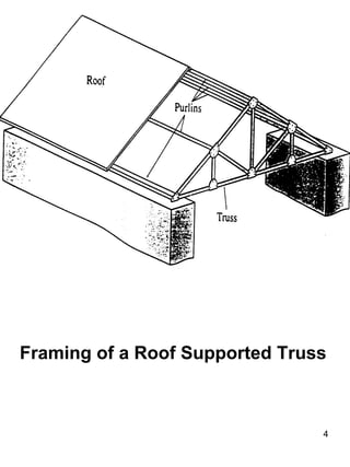
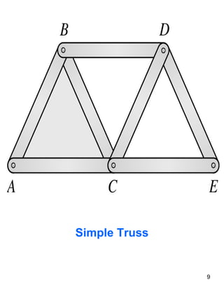
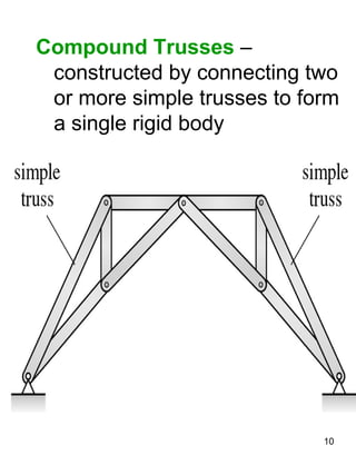
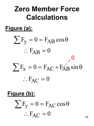
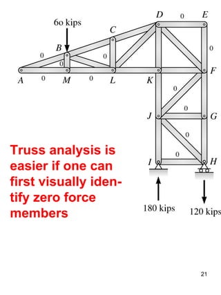
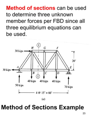
Truss Structures
Truss Definitions and Details 1
Truss: Mimic Beam Behavior
2
Bridge Truss Details 3
Framing of a Roof Supported Truss
4
5
Common Roof Trusses
6
Common
Bridge
Trusses
Buckling Calculations
2
weak
cr 2
EI
P
( L)
buckling force
π
=
=
k
effective length factor
1 for an ideal truss member
=
=
k
k
7
Types of Trusses
Basic Truss Element
≡ three member triangular truss
Simple Trusses – composed of
basic truss elements
m = 3 + 2(j - 3) = 2j - 3
for a simple truss
m ≡ total number of members
j ≡ total number of joints
8
Simple Truss
9
Compound Trusses –
constructed by connecting two
or more simple trusses to form
a single rigid body
10
Complex Trusses – truss that is
neither simple nor compound
11
Analysis of Trusses
The analysis of trusses is usually
based on the following simplifying
assumptions:
•The centroidal axis of each
member coincides with the line
connecting the centers of the
adjacent members and the
members only carry axial force.
•All members are connected
only at their ends by frictionless
hinges in plane trusses.
•All loads and support reactions
are applied only at the joints.
12
The reason for making these
assumptions is to obtain an ideal
truss, i.e., a truss whose mem-
bers are subjected only to axial
forces.
13
Primary Forces ≡ member axial
forces determined from the
analysis of an ideal truss
Secondary Forces ≡ deviations
from the idealized forces, i.e.,
shear and bending forces in a
truss member.
Our focus will be on primary
forces. If large secondary forces
are anticipated, the truss should
be analyzed as a frame.
Method of Joints
Method of Joints - the axial
forces in the members of a
statically determinate truss are
determined by considering the
equilibrium of its joints.
Tensile (T) axial member force
is indicated on the joint by an
arrow pulling away from the joint.
Compressive (C) axial member
force is indicated by an arrow
pushing toward the joint.
14
15
Method of Joints
Example C
22 kips
16
Truss Solution
17
Zero Force Members:
(a) If only two noncollinear
members are connected to a
joint that has no external loads
or reactions applied to it, then
the force in both members is
zero.
(b) If three members, two of
which are collinear, are
connected to a joint that has no
external loads or reactions
applied to it, then the force in
the member that is not
collinear is zero.
18
19Zero Force Members
θ
θ
Zero Member Force
Calculations
Figure (a):
y ABF 0 F cos= = θ∑
ABF 0∴ =
x AC ABF 0 F F sin= = + θ∑
0
ACF 0∴ =
Figure (b):
y ACF 0 F cos= = θ∑
ACF 0∴ = 20
Truss analysis is
easier if one can
first visually iden-
tify zero force
members
21
Method of Sections
The method of sections enables
one to determine forces in
specific truss members directly.
Method of Sections ≡ involves
cutting the truss into two portions
(free body diagrams, FBD) by
passing an imaginary section
through the members whose
forces are desired. Desired
member forces are determined by
considering equilibrium of one of
the two FBD of the truss.
22
Method of sections can be used
to determine three unknown
member forces per FBD since all
three equilibrium equations can
be used.
Method of Sections Example
23
BC
HG
HC
F __________
F __________
F __________
=
=
=
24
Statics Principle of
Transmissibility
25
Transmissibility principle
of statics states that a
force can be applied at any
point on its line of action
without a change in the
external effects
26
27
BC
GF
F ____
F ____
=
=
JC
JF
F ____
F ____
=
=
28
K-Truss Solution
29
Determinacy and Stability
Internal Stability ≡ number and
arrangement of members is
such that the truss does not
change its shape when
detached from the supports.
External Instability ≡ instability
due to insufficient number or
arrangement of external
supports.
30
Internal Stability
m < 2j – 3
⇒ truss is internally
unstable
m ≥ 2j – 3
⇒ truss is internally stable
provided it is geometrically
stable
m ≡ total number of members
j ≡ total number of joints
Geometric stability in the
second condition requires that the
members be properly arranged.
31
Statically Determinate Truss ≡
if all the forces in all its members
as well as all the external reac-
tions can be determined by
using the equations of
equilibrium.
Statically Indeterminate Truss
≡ if all the forces in all its mem-
bers as well as all the external
reactions cannot be determined
by using the equations of equi-
librium.
External Indeterminacy ≡
excess number of support
reactions
32
33
Internal Indeterminacy ≡ excess
number of members
Redundants ≡ excess members or
reactions
Number of redundants defines the
degree of static indeterminacy I
Summary
m + R < 2j
⇒ statically unstable truss
m + R = 2j
⇒ statically determinate truss
m + R ≥ 2j
⇒ statically indeterminate
truss
The first condition is always
true.
But, the last two conditions are
true if and only if the truss is
geometrically stable.
The analysis of unstable
trusses will always lead to
inconsistent, indeterminant, or
infinite results.
34
Truss Determinacy Calculations
35
Truss Determinacy Calculations
36
37Equations of Condition:
Plane Trusses

Ce 382 l5 truss structures

  • 1.
  • 2.
  • 3.
  • 4.
    Framing of aRoof Supported Truss 4
  • 5.
  • 6.
  • 7.
    Buckling Calculations 2 weak cr 2 EI P (L) buckling force π = = k effective length factor 1 for an ideal truss member = = k k 7
  • 8.
    Types of Trusses BasicTruss Element ≡ three member triangular truss Simple Trusses – composed of basic truss elements m = 3 + 2(j - 3) = 2j - 3 for a simple truss m ≡ total number of members j ≡ total number of joints 8
  • 9.
  • 10.
    Compound Trusses – constructedby connecting two or more simple trusses to form a single rigid body 10
  • 11.
    Complex Trusses –truss that is neither simple nor compound 11
  • 12.
    Analysis of Trusses Theanalysis of trusses is usually based on the following simplifying assumptions: •The centroidal axis of each member coincides with the line connecting the centers of the adjacent members and the members only carry axial force. •All members are connected only at their ends by frictionless hinges in plane trusses. •All loads and support reactions are applied only at the joints. 12
  • 13.
    The reason formaking these assumptions is to obtain an ideal truss, i.e., a truss whose mem- bers are subjected only to axial forces. 13 Primary Forces ≡ member axial forces determined from the analysis of an ideal truss Secondary Forces ≡ deviations from the idealized forces, i.e., shear and bending forces in a truss member. Our focus will be on primary forces. If large secondary forces are anticipated, the truss should be analyzed as a frame.
  • 14.
    Method of Joints Methodof Joints - the axial forces in the members of a statically determinate truss are determined by considering the equilibrium of its joints. Tensile (T) axial member force is indicated on the joint by an arrow pulling away from the joint. Compressive (C) axial member force is indicated by an arrow pushing toward the joint. 14
  • 15.
  • 16.
  • 17.
  • 18.
    Zero Force Members: (a)If only two noncollinear members are connected to a joint that has no external loads or reactions applied to it, then the force in both members is zero. (b) If three members, two of which are collinear, are connected to a joint that has no external loads or reactions applied to it, then the force in the member that is not collinear is zero. 18
  • 19.
  • 20.
    Zero Member Force Calculations Figure(a): y ABF 0 F cos= = θ∑ ABF 0∴ = x AC ABF 0 F F sin= = + θ∑ 0 ACF 0∴ = Figure (b): y ACF 0 F cos= = θ∑ ACF 0∴ = 20
  • 21.
    Truss analysis is easierif one can first visually iden- tify zero force members 21
  • 22.
    Method of Sections Themethod of sections enables one to determine forces in specific truss members directly. Method of Sections ≡ involves cutting the truss into two portions (free body diagrams, FBD) by passing an imaginary section through the members whose forces are desired. Desired member forces are determined by considering equilibrium of one of the two FBD of the truss. 22
  • 23.
    Method of sectionscan be used to determine three unknown member forces per FBD since all three equilibrium equations can be used. Method of Sections Example 23
  • 24.
  • 25.
  • 26.
    Transmissibility principle of staticsstates that a force can be applied at any point on its line of action without a change in the external effects 26
  • 27.
  • 28.
  • 29.
  • 30.
    Determinacy and Stability InternalStability ≡ number and arrangement of members is such that the truss does not change its shape when detached from the supports. External Instability ≡ instability due to insufficient number or arrangement of external supports. 30
  • 31.
    Internal Stability m <2j – 3 ⇒ truss is internally unstable m ≥ 2j – 3 ⇒ truss is internally stable provided it is geometrically stable m ≡ total number of members j ≡ total number of joints Geometric stability in the second condition requires that the members be properly arranged. 31
  • 32.
    Statically Determinate Truss≡ if all the forces in all its members as well as all the external reac- tions can be determined by using the equations of equilibrium. Statically Indeterminate Truss ≡ if all the forces in all its mem- bers as well as all the external reactions cannot be determined by using the equations of equi- librium. External Indeterminacy ≡ excess number of support reactions 32
  • 33.
    33 Internal Indeterminacy ≡excess number of members Redundants ≡ excess members or reactions Number of redundants defines the degree of static indeterminacy I Summary m + R < 2j ⇒ statically unstable truss m + R = 2j ⇒ statically determinate truss m + R ≥ 2j ⇒ statically indeterminate truss
  • 34.
    The first conditionis always true. But, the last two conditions are true if and only if the truss is geometrically stable. The analysis of unstable trusses will always lead to inconsistent, indeterminant, or infinite results. 34
  • 35.
  • 36.
  • 37.