Downloaded 548 times

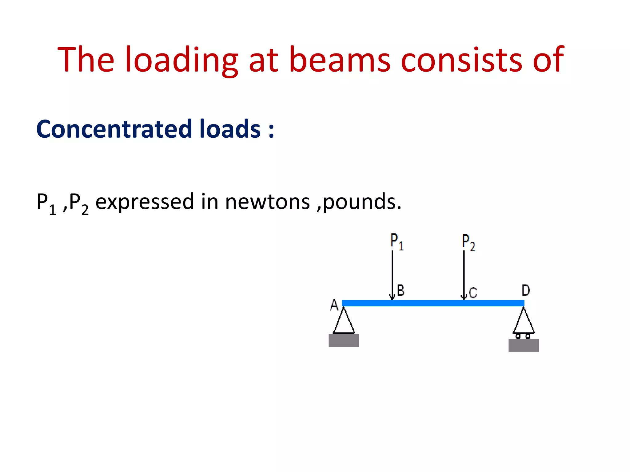
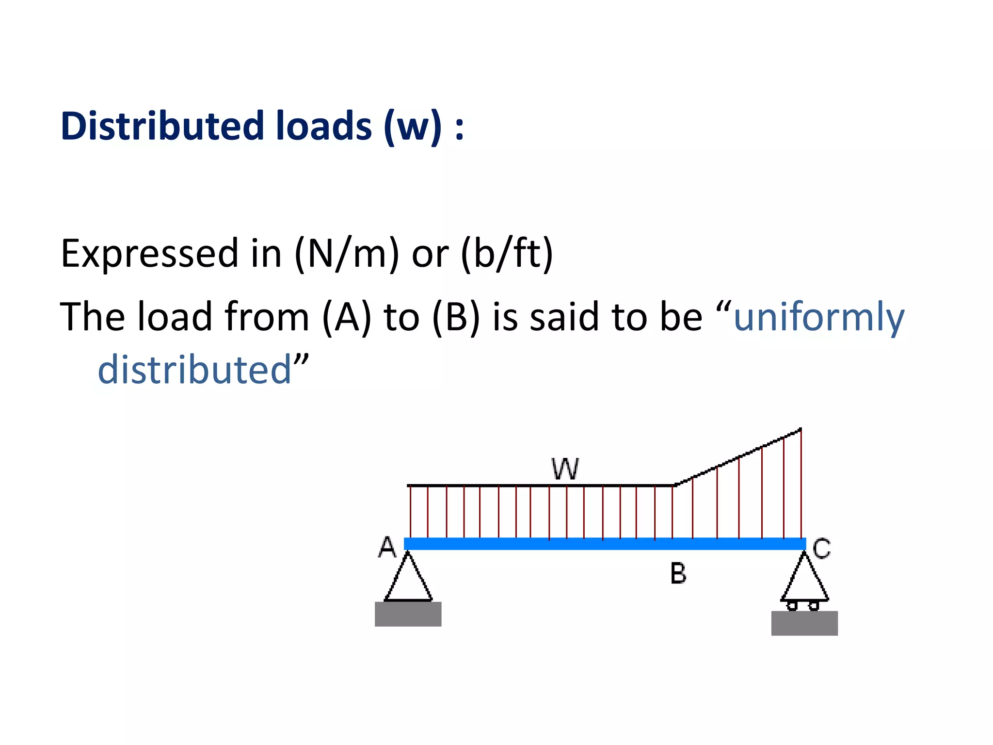
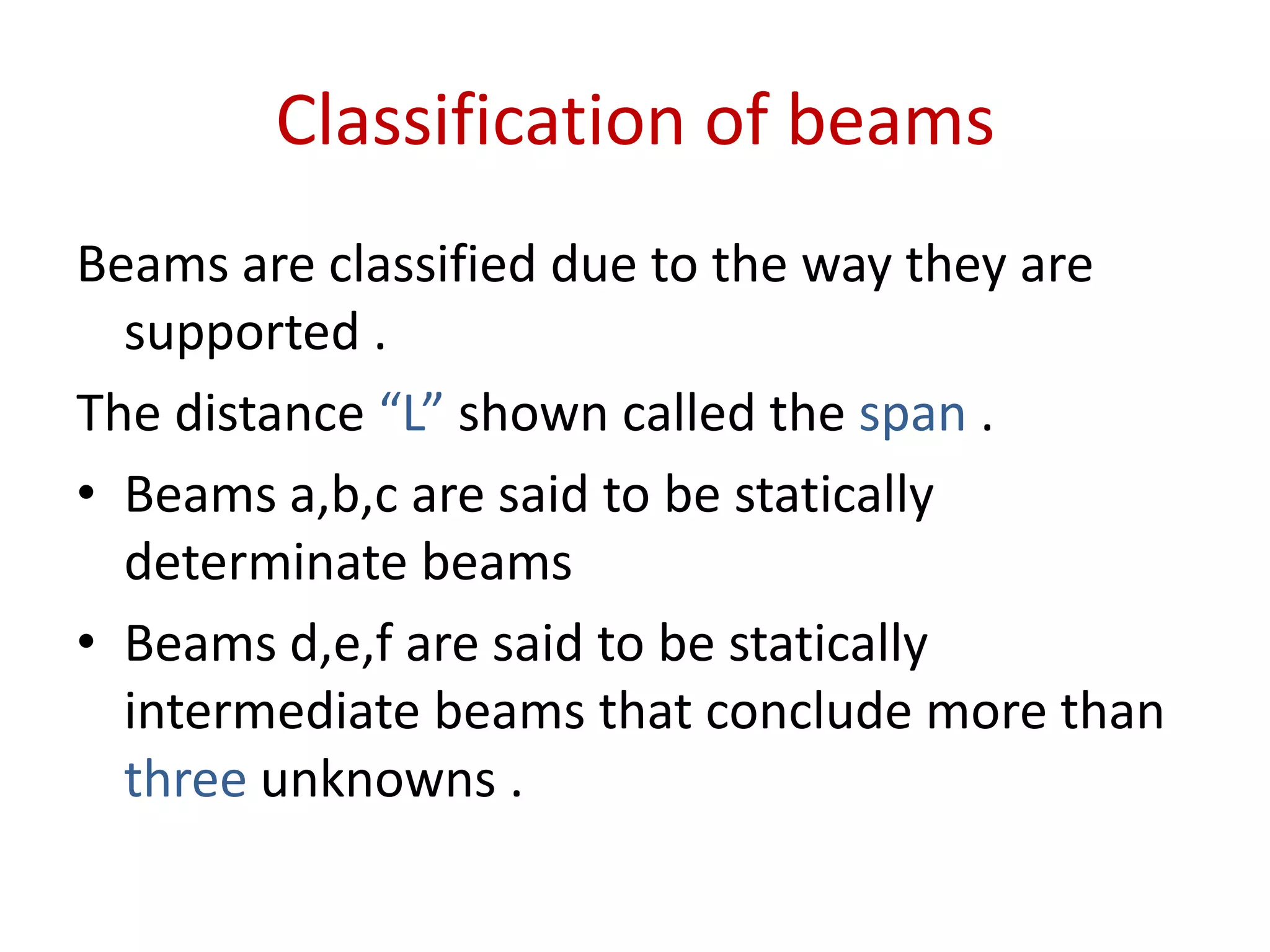
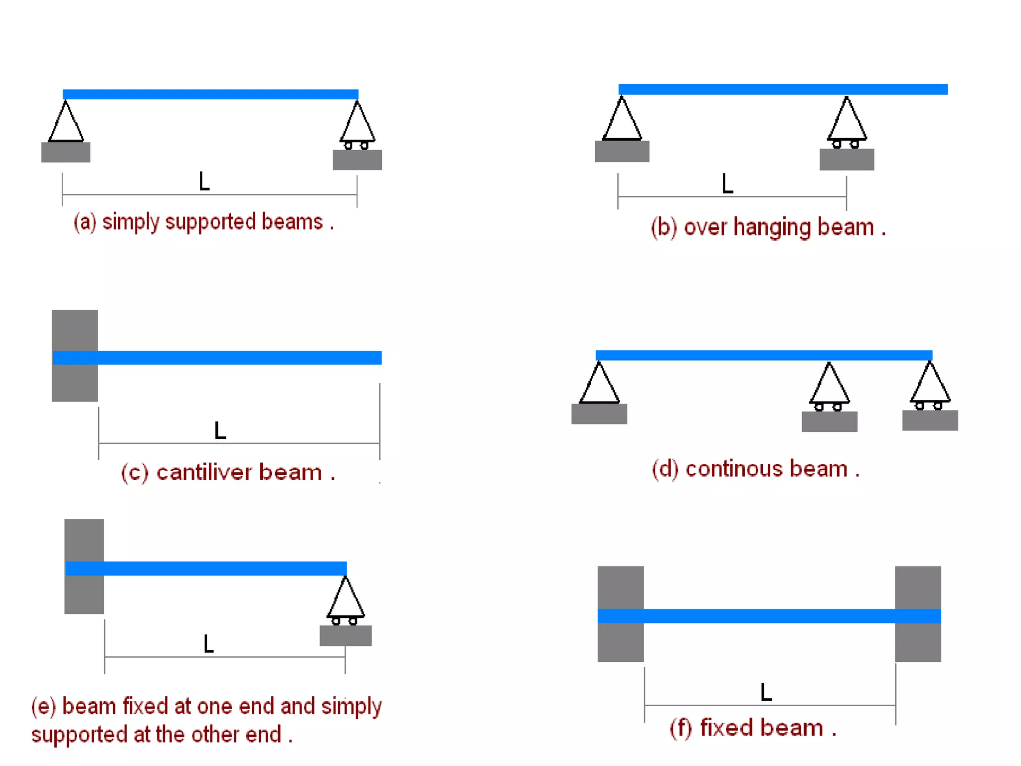
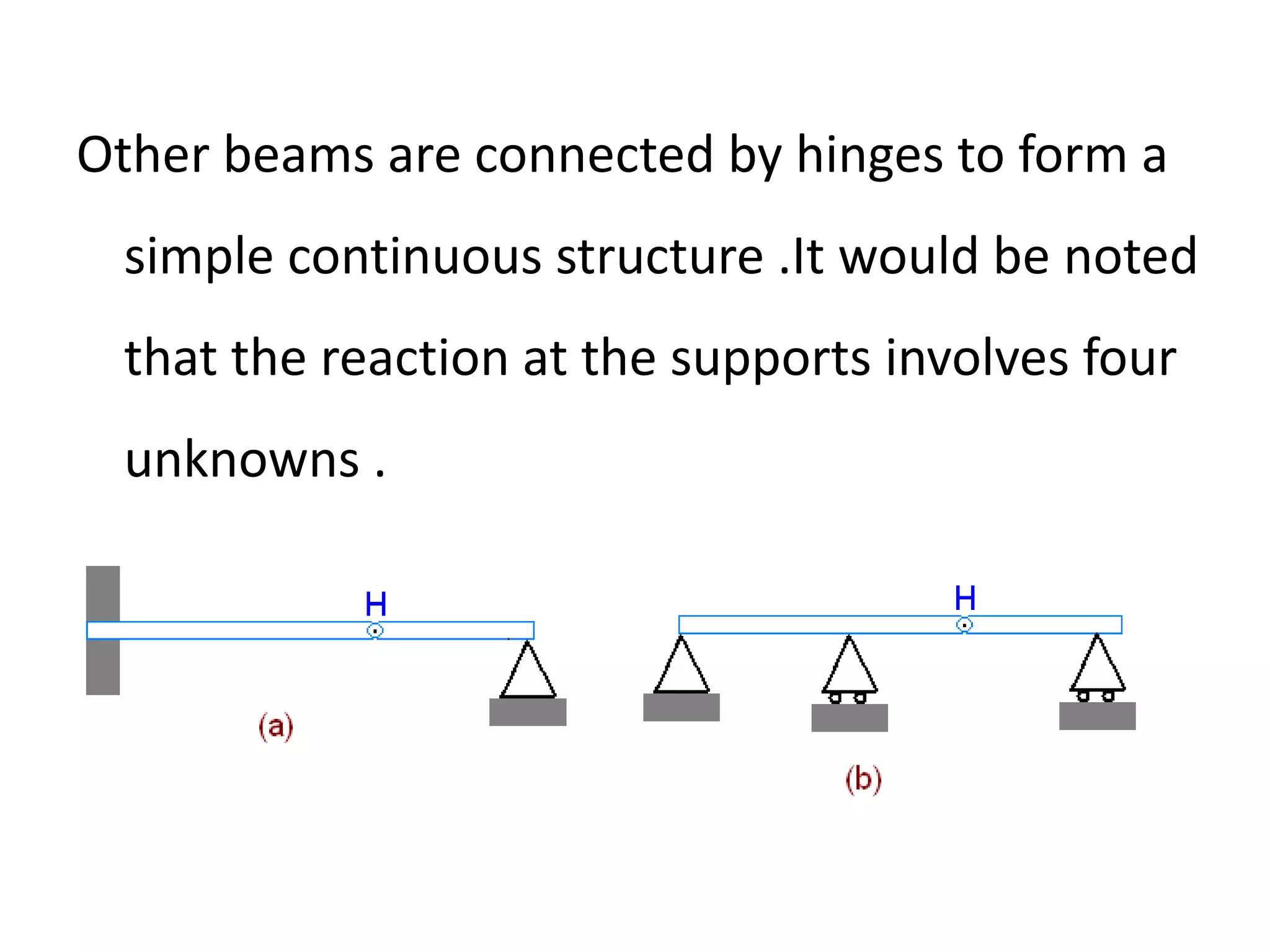
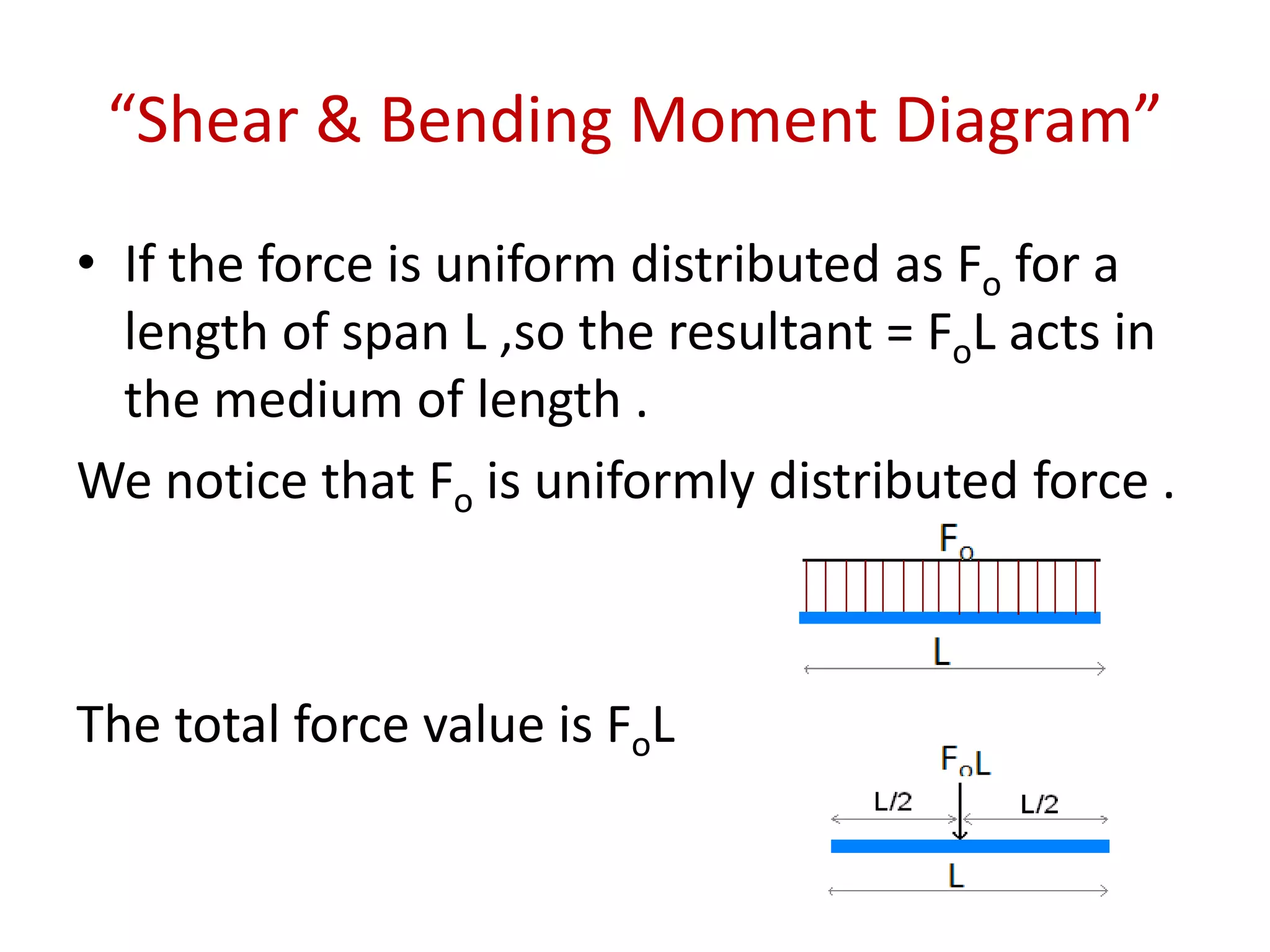
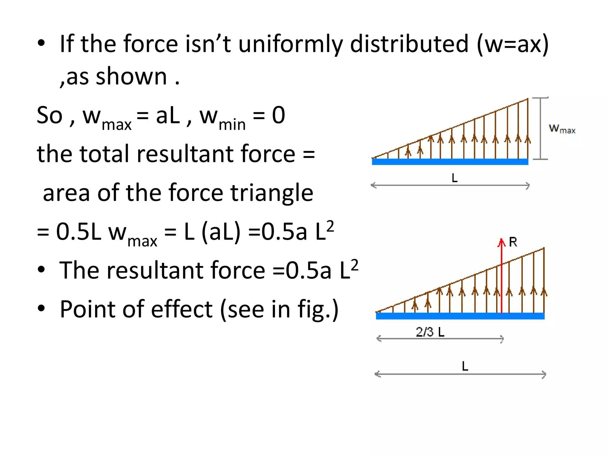
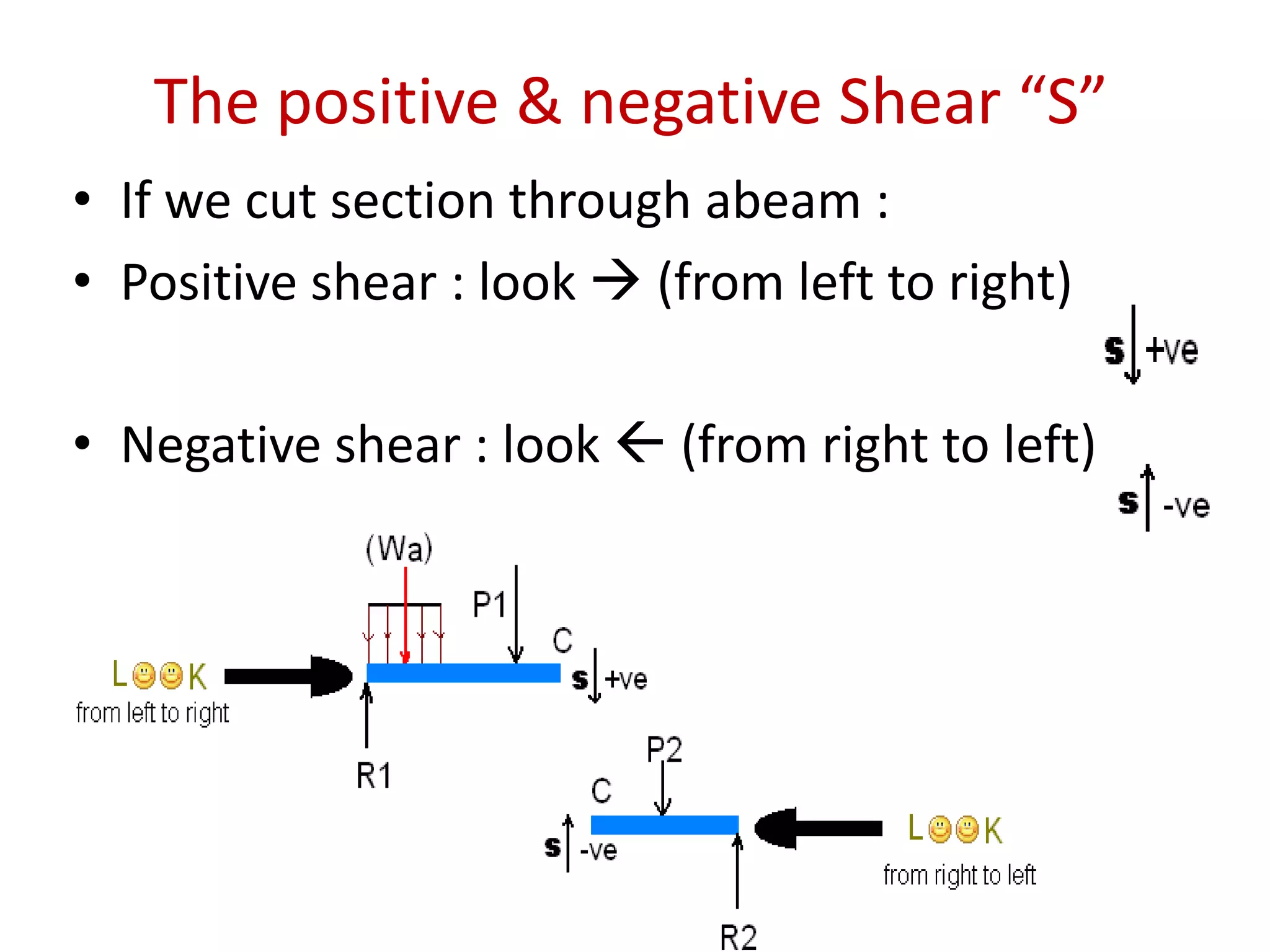
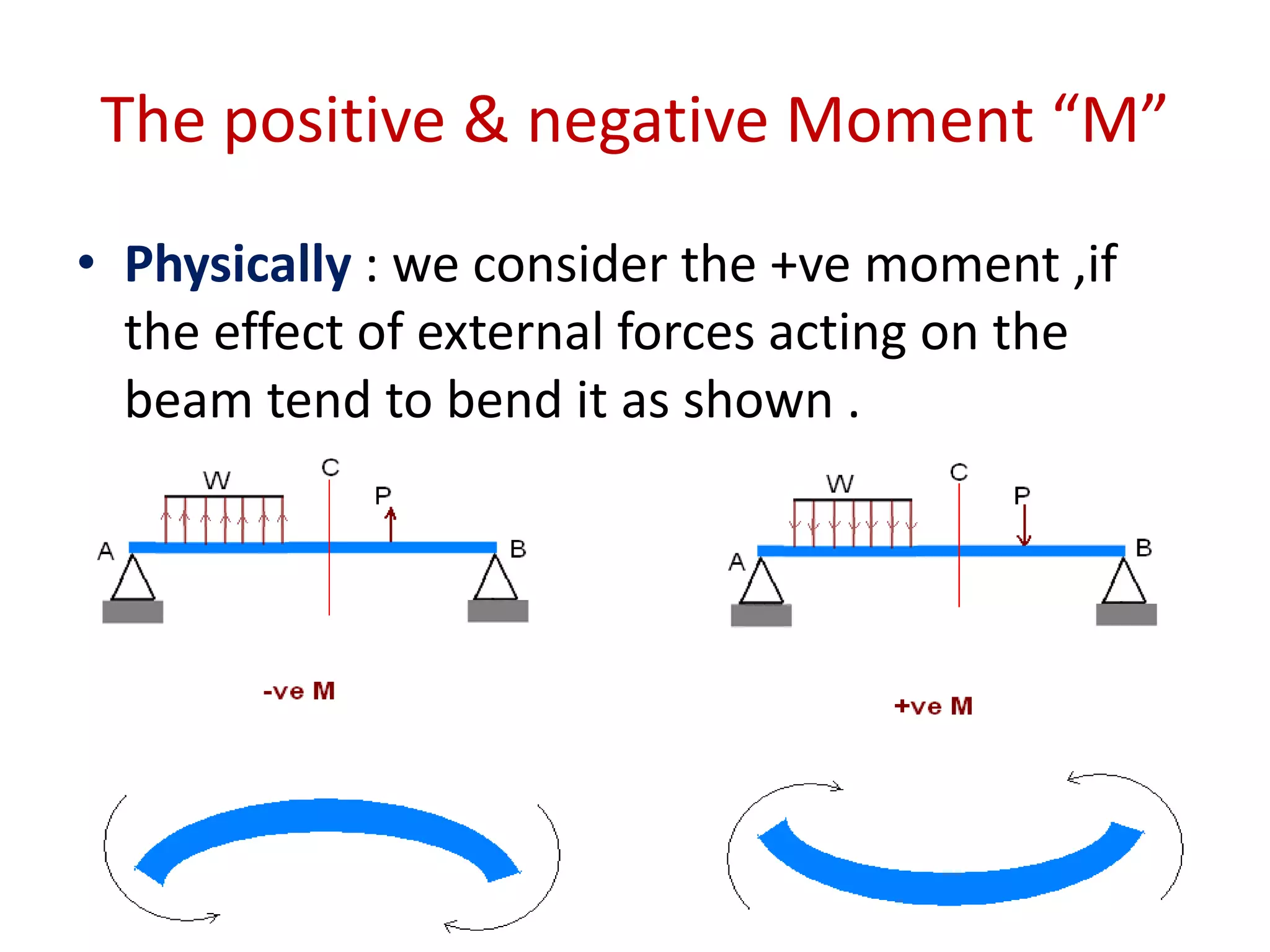
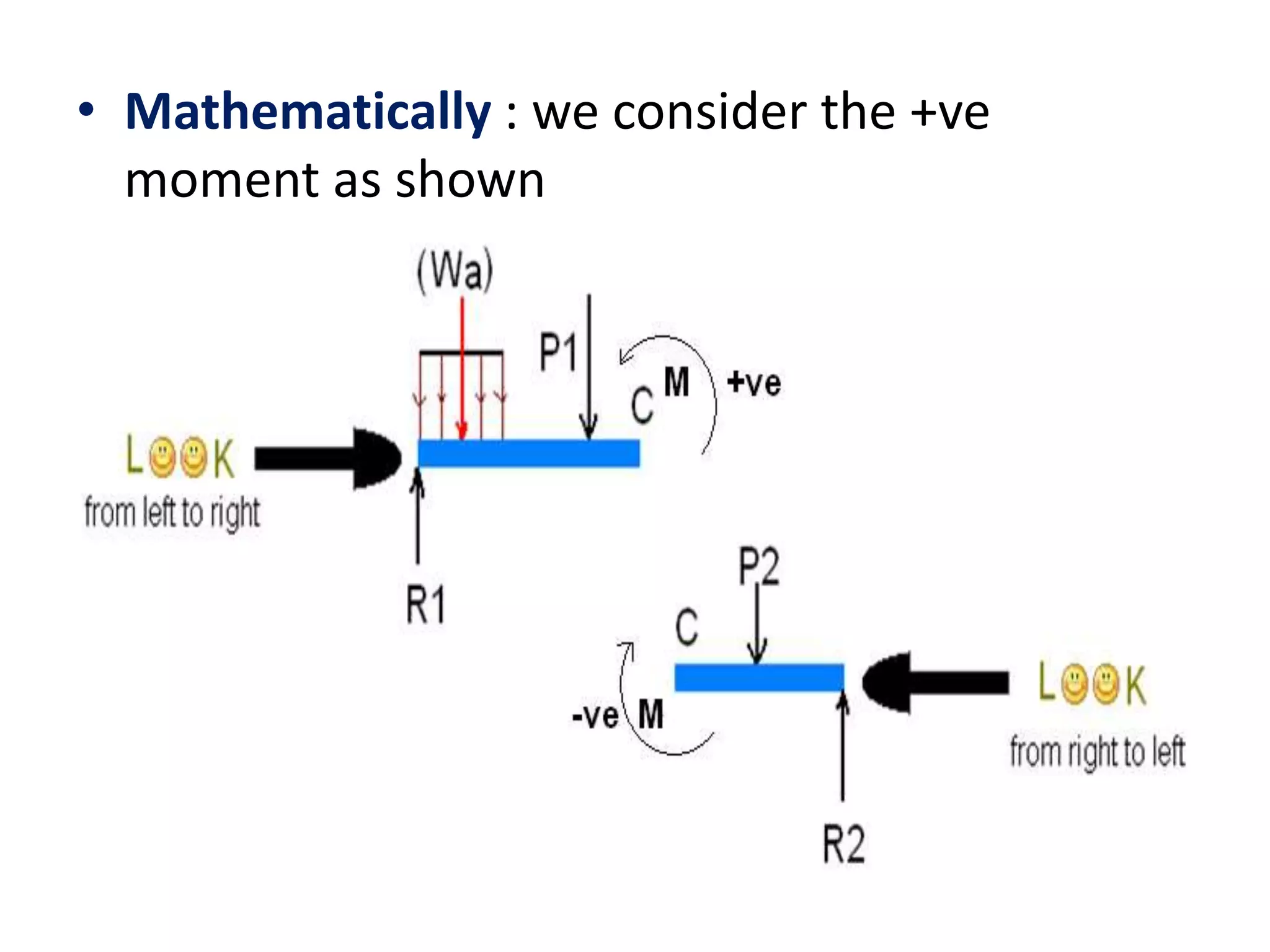
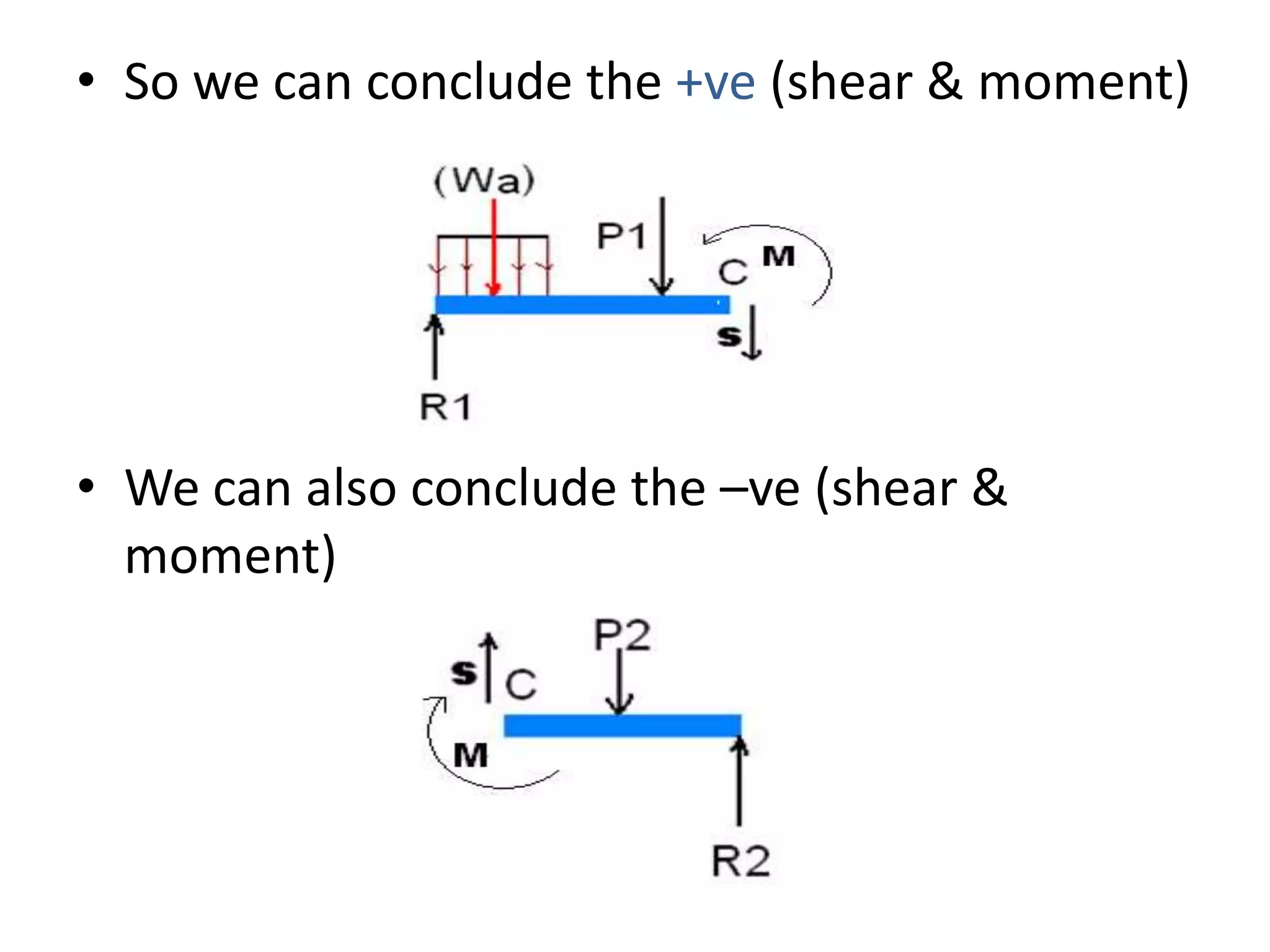

This chapter discusses the analysis and design of beams, which are structural members that support loads applied at different points. Beams can be subjected to concentrated loads or distributed loads. Beams are classified based on their support conditions, with statically determinate beams having three unknowns and statically indeterminate beams having more than three unknowns. Shear and bending moment diagrams are constructed to determine the internal shear and moment forces in the beam resulting from the applied loads. The positive and negative directions of shear and bending moment are defined.