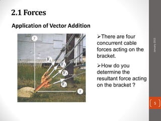
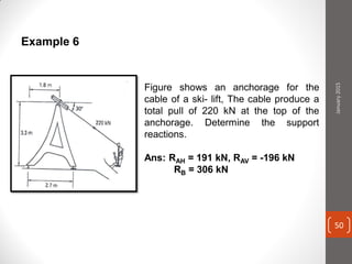
The cable produces a total pull of 220 kN at the top of the anchorage. Let's break this problem down step-by-step:
1) Resolve the 220 kN force into horizontal (RAH) and vertical (RAV) components:
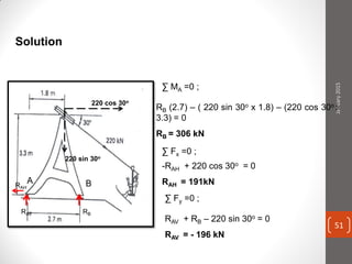
RAH = 220 cos 30° = 191 kN
RAV = 220 sin 30° = -196 kN (note the negative sign indicates downward direction)
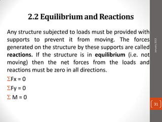
2) The horizontal and vertical equilibrium equations are satisfied:
ΣH = RAH - 0 = 0
ΣV = RAV - (-196) = 0
Therefore, the support reactions are:
RAH = 191 kN
RAV = -196 kN


![01 01 chapgere[1]](https://cdn.slidesharecdn.com/ss_thumbnails/01-01chapgere1-130611230425-phpapp02-thumbnail.jpg?width=640&height=640&fit=bounds)


![Ctm 154[1]](https://cdn.slidesharecdn.com/ss_thumbnails/ctm1541-190506153756-thumbnail.jpg?width=640&height=640&fit=bounds)


