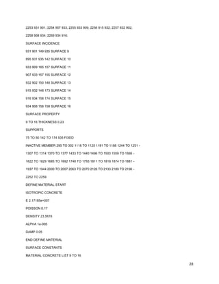
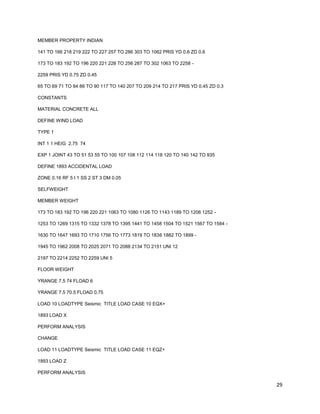
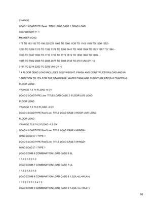
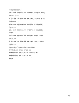
The document provides guidance on manually checking inputs and outputs when using the structural analysis software STAADPRO. It recommends verifying that the model, loads, and support conditions are correctly defined. It also suggests checking results like reactions, forces and moments by calculating values manually. An example model is checked by manually calculating loads, periods, forces and comparing to STAADPRO results to validate the software output. Manual checks help ensure accurate modeling and error-free analysis and design.
Shear, bond bearing,camber & deflection in prestressed concreteMAHFUZUR RAHMAN
This Presentation was presented as a partial fulfillment of Prestressed Concrete Design Lab Course. Behavior & Design of Prestress on above topic is shortly discussed on the presentation. The part "Shear & Shear Design in Prestressed" Concrete was prepared by me. Other topics were prepared by other members of my group. Thanks to all my teachers & friends who helped us in different stages during preparation of the total presentation.
Topics:
1, Introduction to Irrigation
2. Methods of Irrigation
3. Indian Agricultural Soils
4. Methods of Improving Soil Fertility & Crop Rotation
5. Soil-Water-Plant Relationship
6. Duty and Delta
7. Depth and Frequency of Irrigation
8. Irrigation Efficiency and Water Logging
Introduction
Necessity and scope of irrigation
Engineering - benefits and ill effects of irrigation
Irrigation development in India
Classification and types of irrigation systems
Soil-water plant relationship and Type of soil
Water requirements of crop and its Important terminology
Duty delta and base period and Irrigation efficiencies
Method of measuring irrigation water
References
information on types of beams, different methods to calculate beam stress, design for shear, analysis for SRB flexure, design for flexure, Design procedure for doubly reinforced beam,
Effect of tendon profile on deflections – Factors
influencing deflections – Calculation of deflections – Short term and long term deflections - Losses
of prestress
CADmantra Technologies Pvt. Ltd. is one of the best Cad training company in northern zone in India . which are provided many types of courses in cad field i.e AUTOCAD,SOLIDWORK,CATIA,CRE-O,Uniraphics-NX, CNC, REVIT, STAAD.Pro. And many courses
Contact: www.cadmantra.com
www.cadmantra.blogspot.com
www.cadmantra.wix.com
A Better Way to Capture and Manage Cement Lab Datapvisoftware
The design and test of cement slurries are integral parts of every cementing job. Variability between wells can make this process time-consuming and expensive. This white paper talks about how to use an integrated database management application to formulates slurries, calculates required weights for all ingredients, generates weight-up sheets, stores test results, and generates lab reports from anywhere, at any time.
Cosmetic shop management system project report.pdfKamal Acharya
Buying new cosmetic products is difficult. It can even be scary for those who have sensitive skin and are prone to skin trouble. The information needed to alleviate this problem is on the back of each product, but it's thought to interpret those ingredient lists unless you have a background in chemistry.
Instead of buying and hoping for the best, we can use data science to help us predict which products may be good fits for us. It includes various function programs to do the above mentioned tasks.
Data file handling has been effectively used in the program.
The automated cosmetic shop management system should deal with the automation of general workflow and administration process of the shop. The main processes of the system focus on customer's request where the system is able to search the most appropriate products and deliver it to the customers. It should help the employees to quickly identify the list of cosmetic product that have reached the minimum quantity and also keep a track of expired date for each cosmetic product. It should help the employees to find the rack number in which the product is placed.It is also Faster and more efficient way.
Hybrid optimization of pumped hydro system and solar- Engr. Abdul-Azeez.pdffxintegritypublishin
Advancements in technology unveil a myriad of electrical and electronic breakthroughs geared towards efficiently harnessing limited resources to meet human energy demands. The optimization of hybrid solar PV panels and pumped hydro energy supply systems plays a pivotal role in utilizing natural resources effectively. This initiative not only benefits humanity but also fosters environmental sustainability. The study investigated the design optimization of these hybrid systems, focusing on understanding solar radiation patterns, identifying geographical influences on solar radiation, formulating a mathematical model for system optimization, and determining the optimal configuration of PV panels and pumped hydro storage. Through a comparative analysis approach and eight weeks of data collection, the study addressed key research questions related to solar radiation patterns and optimal system design. The findings highlighted regions with heightened solar radiation levels, showcasing substantial potential for power generation and emphasizing the system's efficiency. Optimizing system design significantly boosted power generation, promoted renewable energy utilization, and enhanced energy storage capacity. The study underscored the benefits of optimizing hybrid solar PV panels and pumped hydro energy supply systems for sustainable energy usage. Optimizing the design of solar PV panels and pumped hydro energy supply systems as examined across diverse climatic conditions in a developing country, not only enhances power generation but also improves the integration of renewable energy sources and boosts energy storage capacities, particularly beneficial for less economically prosperous regions. Additionally, the study provides valuable insights for advancing energy research in economically viable areas. Recommendations included conducting site-specific assessments, utilizing advanced modeling tools, implementing regular maintenance protocols, and enhancing communication among system components.
Welcome to WIPAC Monthly the magazine brought to you by the LinkedIn Group Water Industry Process Automation & Control.
In this month's edition, along with this month's industry news to celebrate the 13 years since the group was created we have articles including
A case study of the used of Advanced Process Control at the Wastewater Treatment works at Lleida in Spain
A look back on an article on smart wastewater networks in order to see how the industry has measured up in the interim around the adoption of Digital Transformation in the Water Industry.
Forklift Classes Overview by Intella PartsIntella Parts
Discover the different forklift classes and their specific applications. Learn how to choose the right forklift for your needs to ensure safety, efficiency, and compliance in your operations.
For more technical information, visit our website https://intellaparts.com
CFD Simulation of By-pass Flow in a HRSG module by R&R Consult.pptxR&R Consult
CFD analysis is incredibly effective at solving mysteries and improving the performance of complex systems!
Here's a great example: At a large natural gas-fired power plant, where they use waste heat to generate steam and energy, they were puzzled that their boiler wasn't producing as much steam as expected.
R&R and Tetra Engineering Group Inc. were asked to solve the issue with reduced steam production.
An inspection had shown that a significant amount of hot flue gas was bypassing the boiler tubes, where the heat was supposed to be transferred.
R&R Consult conducted a CFD analysis, which revealed that 6.3% of the flue gas was bypassing the boiler tubes without transferring heat. The analysis also showed that the flue gas was instead being directed along the sides of the boiler and between the modules that were supposed to capture the heat. This was the cause of the reduced performance.
Based on our results, Tetra Engineering installed covering plates to reduce the bypass flow. This improved the boiler's performance and increased electricity production.
It is always satisfying when we can help solve complex challenges like this. Do your systems also need a check-up or optimization? Give us a call!
Work done in cooperation with James Malloy and David Moelling from Tetra Engineering.
More examples of our work https://www.r-r-consult.dk/en/cases-en/
Vaccine management system project report documentation..pdfKamal Acharya
The Division of Vaccine and Immunization is facing increasing difficulty monitoring vaccines and other commodities distribution once they have been distributed from the national stores. With the introduction of new vaccines, more challenges have been anticipated with this additions posing serious threat to the already over strained vaccine supply chain system in Kenya.
Quality defects in TMT Bars, Possible causes and Potential Solutions.PrashantGoswami42
Maintaining high-quality standards in the production of TMT bars is crucial for ensuring structural integrity in construction. Addressing common defects through careful monitoring, standardized processes, and advanced technology can significantly improve the quality of TMT bars. Continuous training and adherence to quality control measures will also play a pivotal role in minimizing these defects.
Explore the innovative world of trenchless pipe repair with our comprehensive guide, "The Benefits and Techniques of Trenchless Pipe Repair." This document delves into the modern methods of repairing underground pipes without the need for extensive excavation, highlighting the numerous advantages and the latest techniques used in the industry.
Learn about the cost savings, reduced environmental impact, and minimal disruption associated with trenchless technology. Discover detailed explanations of popular techniques such as pipe bursting, cured-in-place pipe (CIPP) lining, and directional drilling. Understand how these methods can be applied to various types of infrastructure, from residential plumbing to large-scale municipal systems.
Ideal for homeowners, contractors, engineers, and anyone interested in modern plumbing solutions, this guide provides valuable insights into why trenchless pipe repair is becoming the preferred choice for pipe rehabilitation. Stay informed about the latest advancements and best practices in the field.
NO1 Uk best vashikaran specialist in delhi vashikaran baba near me online vas...Amil Baba Dawood bangali
Contact with Dawood Bhai Just call on +92322-6382012 and we'll help you. We'll solve all your problems within 12 to 24 hours and with 101% guarantee and with astrology systematic. If you want to take any personal or professional advice then also you can call us on +92322-6382012 , ONLINE LOVE PROBLEM & Other all types of Daily Life Problem's.Then CALL or WHATSAPP us on +92322-6382012 and Get all these problems solutions here by Amil Baba DAWOOD BANGALI
#vashikaranspecialist #astrologer #palmistry #amliyaat #taweez #manpasandshadi #horoscope #spiritual #lovelife #lovespell #marriagespell#aamilbabainpakistan #amilbabainkarachi #powerfullblackmagicspell #kalajadumantarspecialist #realamilbaba #AmilbabainPakistan #astrologerincanada #astrologerindubai #lovespellsmaster #kalajaduspecialist #lovespellsthatwork #aamilbabainlahore#blackmagicformarriage #aamilbaba #kalajadu #kalailam #taweez #wazifaexpert #jadumantar #vashikaranspecialist #astrologer #palmistry #amliyaat #taweez #manpasandshadi #horoscope #spiritual #lovelife #lovespell #marriagespell#aamilbabainpakistan #amilbabainkarachi #powerfullblackmagicspell #kalajadumantarspecialist #realamilbaba #AmilbabainPakistan #astrologerincanada #astrologerindubai #lovespellsmaster #kalajaduspecialist #lovespellsthatwork #aamilbabainlahore #blackmagicforlove #blackmagicformarriage #aamilbaba #kalajadu #kalailam #taweez #wazifaexpert #jadumantar #vashikaranspecialist #astrologer #palmistry #amliyaat #taweez #manpasandshadi #horoscope #spiritual #lovelife #lovespell #marriagespell#aamilbabainpakistan #amilbabainkarachi #powerfullblackmagicspell #kalajadumantarspecialist #realamilbaba #AmilbabainPakistan #astrologerincanada #astrologerindubai #lovespellsmaster #kalajaduspecialist #lovespellsthatwork #aamilbabainlahore #Amilbabainuk #amilbabainspain #amilbabaindubai #Amilbabainnorway #amilbabainkrachi #amilbabainlahore #amilbabaingujranwalan #amilbabainislamabad
1. 1
MANUAL CHECKING OF STAADPRO INPUTS AND OUTPUT RESULTS
T.Rangarajan. Consulting Structural Engineer, Coimbatore, India.
INTRODUCTION:
It is well known fact that users of any software for structural analysis and Design do not
know whether the program is having any bugs or its correctness while using. Since any
program developed may contain some error or bugs it is necessary for the users to
check the model and analysis and design results at some point to check the results
manually so as to make sure that:
1. The input data while modeling the structures is correct.
2. The assumed and the input loads on the structure are in par with the actual
condition of the structure.
3. The support condition considered are as per site condition.
4. A countercheck to verify that ΣH=0; ΣV=0 and ΣM=0.
Also users should be knowing the universal well spread phrase of the word
“GOINGOOUT”.
An attempt has been made to list the number of manual checks that can be carried out
while using STAADPRO and as an aid the following check list are prepared.
The list of checks may be applicable not only to STAADPRO but also to any software
used for structural analysis and design.
MODEL CHECKING:
It is important to check the UNITS at every stage while modeling since it may lead to a
unexpected error in the output. While modeling use of length units may be in meter for
beam, column and plate and while entering the properties it is usual practice to make
use of either mms or inch unit since we know the dimensions which are familiar.
While inputting the LOADS on members check the UNIT system is in KN and meter
system since the program continues to use the previous unit till it is changed.
Before inputting the LOADS to the structure facility is available in STAADPRO as per
the screen shot.
a. Check Multiple Structures.
Some times by mistake the user would have without his knowledge created too
many members and structure. Better use this tool menu to remove the multiple
2. 2
structures. It is the responsibility of the applicator to verify that there exists only
one structure and not more than it for any model.
**********************************************************************
Check for solids with Negative Volume (Jacobian)
Check for Warped Solids.
*******************************************************************
2. Check Duplicate :
a. Nodes.
b. Members.
c. Plates.
It is natural and human nature to make mistake and error while entering data while
creating the model by means of Nodes, Members (Beam and column) and plates in
STAADPRO. To take care before continuing and to alleviate cumulating more errors
it is good practice to check whether there is any duplicate nodes, members and
plates which would have slipped in the model while creating the model by means of
the tool available as shown in the screen shot.
3. Check Orphan Nodes:
Sometimes by mistake some nodes would have been added and no members are
formed through the nodes and they would have been left as an orphan. It is
necessary to check and remove these orphan nodes to proceed further.
3. 3
4.Check for Warped plates:
If the model is created by means of plates it is good to check whether the plates
formed contain any warp using the command “Check for Warped plates” after
selecting the plates.
5.Check Improperly connected plates and Check Beam Plate connectivity:
The above two commands in STAADPRO enable the user to check the continuity of
the plate with other plates and beams formed while modeling the structure. If they are
not well welded then the distribution of forces and continuity between them cannot be
guaranteed. Hence these checks are important.
The check Beam plate connectivity check is important in the case of Wall and plate
modeling. Vie sec of “AD.2005.1.3 Wall-slab interface considerations in finite
element meshing” the Staad manual for more clarification.
Apart from the above available tool for checking the model the following manual
calculations of certain simple items will be of use to check the input data and
correctness of the model before proceeding to analysis and design.
LOADS:
Correct assessment of loads both dead and live loads are important since
excessive assumed loads may lead to uneconomical member sizes and footing
sizes. Also excessive loads will be adding more weight in the case of seismic
forces.
In order to have equilibrium i.e .ΣV=0 under the Load case DEAD LOAD calculate
the total dead load on all floor slabs and check it against the output by the
program.
METHOD TO CHECK:
Using a single support for the whole structure RUN the ANALYSIS and find out the
total support reaction in Y axis i.e FY from the output of the program. Check
whether the above two values are in agreement to the manually calculated
values. If the results vary then there is some error or mistake took place while
entering the input.
The same procedure can be carried out for the LIVE LOAD for both FLOOR LIVE
LOAD and ROOF LIVE LOAD cases also.
4. 4
If the single support is not considered or modeled then use all the supports and
copy the values of Fy to EXCEL and get the sum of the FY and check whether it
tallies with the manually calculated values.
WIND LOAD:
It is possible to generate the wind load by the program provided it is defined at
the start by adding the required input data. In order to check the values
generated by the program a simple manual check can be made as described.
To find the point load FX or FZ at a joint as nodal wind force calculate the
tributary area for the corresponding node and multiply it with the intensity of
loading.
For example:
Area = (h1+h2)/2*(L1+L2)/2* intensity of loading.
Please note that the consistence unit shall be used.
Where h1 and h2 are the height above and below the joint in meters and L1 and
L2 are the width of the bay on either side of the node in meter units. If h1 =4.0m
and h2=3.0m, L1=5.0m and L2=6.0m then the tributary area for the node is
=(4+3)/2*(5+6)/2 = 19.25sq.m.
Using an intensity of 1KN/sq.m the nodal force shall be =19.25 KN. This can be
verified with the values generated by the program.
SUPPORT CONDITIONS:
Usually while modeling a structure either FIXED or HINGED support condition is
proposed. If the support condition is FIXED the there shall be six restraints i.s.
FX,FY ,FZ, Mx, My and Mz
For HINGED there shall be no moments.
In order to account for the soil spring the modulus of subgrade reaction Ks has to be
considered for the support condition.
5. 5
MANUAL CHECK AGAINST STAAD RESULTS FOR SEISMIC FORCES
********************************************************************************************
For the verification of the values generated by the STAADPRO program an example is
taken up to illustrate. The input is also given in the appendix so that the STAADPRO
user can copy and run it to know how it is checked.
The frame modeled is checked easily for the following items:
The structure is 36x21m and is symmetrical in x and Z direction as well as in vertical
elevation and its total height from the footing is 74m.(21 storey)
The building is in Zone III and the time period as per IS 1893-2002(PartI) for infill is
taken 0.09h/√d.
After analysis through STAADPRO the followings check is carried out to verify and
check the results between manual calculation and the software results.
--------------------------------------------------------------------------------------------------------------------
A. TIME PERIOD:
As per IS CODE 1893-2002(Part I) T =0.09h/ √d where d is the direction
along the EQ forces.
Tx =0.09x74/ √36 =1.11 Sec.
Tz =0.09h/ √21 =1.453 Sec.
The output of STAADPRO is
TIME PERIOD FOR X 1893 LOADING = 1.11000 SEC
TIME PERIOD FOR Z 1893 LOADING = 1.45333 SEC
**********************************************************************************************
Happy to note from the above comparison that the program is doing fine upto this
stage.
______________________________________________________________________
B. To check The Dead load as per Staad for 19 floors
a.)slab including self weight of columns, beams, brick wall weight and
shear wall as per dimensions that were provided by the user.
In the program under the load case 1 the following loads are input:
1. Self weight (columns,beams and shear walls for the entire building)
2. Brickwall over the exterior beams except on shear wall only are added.
3. The dead load on slab- Self weight of slab+Finish+Construction load +15% for
furniture, staircase, water tank etc is added with an intensity of 6KN/Sq.m.
A manual check for these items are carried out as:
6. 6
a. Dead load: Area of floor x no. of floors x intensity of load
=36x21x6x20 = 90720Kn.
If the input is arranged for this in STAADPRO we get the same value as
calculated manually from the output.
*************************************************************************************
b. Brickwall load:
Total length of beam in one floor =2x{(36.0-6.0)+(21.0-6.0)}= 90.0m
Load per floor = 90.0x12Kn/m =1080.0Kn
Load due to brickwall alround exterior beams =19x1080 =20520.00Kn
Load due to Parapet 1.0 m height of 4.5” wall=2x{36+21}x5.0Kn/m=570.0Kn
Total dead load due to brickwall =20520+570.0 =21090.00Kn.
c. SELF WEIGHT OF:
1. COLUMNS =0.6X0.6X74.0Mx40nox23.562 =25106.72 Default density value
of 23.562Kn/m^3 is taken from STAAD program.
2. Beams for all floors = 0.75x0.45x23.562x{(36x4+21x9)}x20 =.52961.489Kn.
GF beam =0.45x0.23x23.562x{30x2+36x2+15x2+21x7)=753.5 KN
d. Shear wall:
4x2x3.0x74.0x0.23x23.562 =9624.60 KN
Total of a+b+c =90720.0+20520.0+21090.0+52961.489+753.5 +9624.60=195669.59Kn
As per STAAD output as furnished below total load =199908.38.
STAAD output is:
**********************************************************************************************
STATIC LOAD/REACTION/EQUILIBRIUM SUMMARY FOR CASE NO. 1
LOADTYPE DEAD TITLE LOAD CASE 1 DEAD LOAD
TOTAL APPLIED LOAD ( KN METE ) SUMMARY (LOADING 1 )
SUMMATION FORCE-X = 0.00
SUMMATION FORCE-Y = -199908.38
SUMMATION FORCE-Z = 0.00
The percentage of difference =(4238.79/199908.38)*100 =2.12%.
*************************************************************************************
C.LIVE LOAD CHECK:
Live load for floor is 3Kn/sq.m(office ) and roof Live load as 1.5 Kn/sq.m as per IS 875
as access is there is taken.
***************************************************************************************
STATIC LOAD/REACTION/EQUILIBRIUM SUMMARY FOR CASE NO. 2
LOADTYPE LIVE TITLE LOAD CASE 2 FLOOR LIVE LOAD
TOTAL APPLIED LOAD ( KN METE ) SUMMARY (LOADING 2 )
7. 7
SUMMATION FORCE-X = 0.00
SUMMATION FORCE-Y = -43092.00
SUMMATION FORCE-Z = 0.00
The above is the result from STAAD.
As per manual calculation is 36x21x19x3Kn/sq.m =43092.0Kn which exactly tally.
STATIC LOAD/REACTION/EQUILIBRIUM SUMMARY FOR CASE NO. 3
LOADTYPE ROOF LIVE TITLE LOAD CASE 3 ROOF LIVE LOAD
TOTAL APPLIED LOAD ( KN METE ) SUMMARY (LOADING 3 )
SUMMATION FORCE-X = 0.00
SUMMATION FORCE-Y = -1134.00
SUMMATION FORCE-Z = 0.00
As per calculation 36x21x1.5 = 1134.00 which is the same as per STAADPRO.
D. CHECK THE VALUE OF SA/G
___________________________________________________________________
Ah =ZISa/(2*R*g)—for the value of Tx and TZ for medium soil the value of
Sa/g for Tx from code =1.36/T =1.36/1.11 = 1.225.
-do- for Tz = 1.36/1.453 = 0.93599.
As per Staad Sa/g for x direction and for Z direction are in agreement with manual
calculation.
*******************************************************************************
STAADPRO OUTPUT:
* TIME PERIOD FOR X 1893 LOADING = 1.11000 SEC *
* SA/G PER 1893= 1.225, LOAD FACTOR= 1.000 *
* FACTOR V PER 1893= 0.0196 X 203723.80 *
*****************************************************************************
* TIME PERIOD FOR Z 1893 LOADING = 1.45333 SEC *
* SA/G PER 1893= 0.936, LOAD FACTOR= 1.000 *
* FACTOR V PER 1893= 0.0150 X 203723.80 *
E. CHECK THE SEISMIC WEIGHT:
Therefore W the EQ load as per IS 1893 by calculation (Manual)
=199908.38+0.25x43092 = 210681.38Kn.
Staad calculates and it gives 203723.8 Kn as shown above against manual
calculation of 2180384Kn which is 7148/218038x100 =3.28%.
8. 8
CONCLUSION:
The above checks can help to a greater extend and it makes sure that the user has
modeled the structure with no mistake and further that there is no error in the input.
After running the analysis also a simple check on the result can be made using the
available formulae for fixed and simple beams.
By the above technique a software user make sure that his model, the analysis result
will yield a error prone design. Once analysis id carried out with error free results then
design can be made either manually or using the same software or excel stand alone
programs.
The above methods gives a clear picture how a software user to check his inputs and
get the maximum use out of any software.
Always better to know two or more than a single software so that a counter check can
be made especially for a large and mega projects to avoid suspicious results and to
continue his design with peace of mind.
References:
1. STAADPRO manual and program.
2. IS CODE 875-Pat 1 to 3.
3. IS CODE 1893-2002 (Part 1).
4. IS CODE 13920.
5. IS CODE 4326.
6. Advance Reinforced Concrete Design by P.C.Varghese.
28. 28
2253 931 901; 2254 907 933; 2255 933 909; 2256 915 932; 2257 932 902;
2258 908 934; 2259 934 916;
SURFACE INCIDENCE
931 901 149 935 SURFACE 9
895 931 935 142 SURFACE 10
933 909 165 157 SURFACE 11
907 933 157 155 SURFACE 12
932 902 150 148 SURFACE 13
915 932 148 173 SURFACE 14
916 934 158 174 SURFACE 15
934 908 156 158 SURFACE 16
SURFACE PROPERTY
9 TO 16 THICKNESS 0.23
SUPPORTS
75 TO 80 142 TO 174 935 FIXED
INACTIVE MEMBER 295 TO 302 1118 TO 1125 1181 TO 1188 1244 TO 1251 -
1307 TO 1314 1370 TO 1377 1433 TO 1440 1496 TO 1503 1559 TO 1566 -
1622 TO 1629 1685 TO 1692 1748 TO 1755 1811 TO 1818 1874 TO 1881 -
1937 TO 1944 2000 TO 2007 2063 TO 2070 2126 TO 2133 2189 TO 2196 -
2252 TO 2259
DEFINE MATERIAL START
ISOTROPIC CONCRETE
E 2.17185e+007
POISSON 0.17
DENSITY 23.5616
ALPHA 1e-005
DAMP 0.05
END DEFINE MATERIAL
SURFACE CONSTANTS
MATERIAL CONCRETE LIST 9 TO 16
29. 29
MEMBER PROPERTY INDIAN
141 TO 166 218 219 222 TO 227 257 TO 286 303 TO 1062 PRIS YD 0.6 ZD 0.6
173 TO 183 192 TO 196 220 221 228 TO 256 287 TO 302 1063 TO 2258 -
2259 PRIS YD 0.75 ZD 0.45
65 TO 69 71 TO 84 86 TO 90 117 TO 140 207 TO 209 214 TO 217 PRIS YD 0.45 ZD 0.3
CONSTANTS
MATERIAL CONCRETE ALL
DEFINE WIND LOAD
TYPE 1
INT 1 1 HEIG 2.75 74
EXP 1 JOINT 43 TO 51 53 55 TO 100 107 108 112 114 118 120 TO 140 142 TO 935
DEFINE 1893 ACCIDENTAL LOAD
ZONE 0.16 RF 5 I 1 SS 2 ST 3 DM 0.05
SELFWEIGHT
MEMBER WEIGHT
173 TO 183 192 TO 196 220 221 1063 TO 1080 1126 TO 1143 1189 TO 1206 1252 -
1253 TO 1269 1315 TO 1332 1378 TO 1395 1441 TO 1458 1504 TO 1521 1567 TO 1584 -
1630 TO 1647 1693 TO 1710 1756 TO 1773 1819 TO 1836 1882 TO 1899 -
1945 TO 1962 2008 TO 2025 2071 TO 2088 2134 TO 2151 UNI 12
2197 TO 2214 2252 TO 2259 UNI 5
FLOOR WEIGHT
YRANGE 7.5 74 FLOAD 6
YRANGE 7.5 70.5 FLOAD 0.75
LOAD 10 LOADTYPE Seismic TITLE LOAD CASE 10 EQX+
1893 LOAD X
PERFORM ANALYSIS
CHANGE
LOAD 11 LOADTYPE Seismic TITLE LOAD CASE 11 EQZ+
1893 LOAD Z
PERFORM ANALYSIS
30. 30
CHANGE
LOAD 1 LOADTYPE Dead TITLE LOAD CASE 1 DEAD LOAD
SELFWEIGHT Y -1
MEMBER LOAD
173 TO 183 192 TO 196 220 221 1063 TO 1080 1126 TO 1143 1189 TO 1206 1252 -
1253 TO 1269 1315 TO 1332 1378 TO 1395 1441 TO 1458 1504 TO 1521 1567 TO 1584 -
1630 TO 1647 1693 TO 1710 1756 TO 1773 1819 TO 1836 1882 TO 1899 -
1945 TO 1962 2008 TO 2025 2071 TO 2088 2134 TO 2151 UNI GY -12
2197 TO 2214 2252 TO 2259 UNI GY -5
* A FLOOR DEAD LOAD INCLUDES SELF WEIGHT, FINISH AND CONSTRUCTION LOAD AND IN
* ADDITION TO 15% FOR THE STAIRCASE, WATER TANK AND FURNITURE ETC(5+0.75)APPR=6
FLOOR LOAD
YRANGE 7.5 74 FLOAD -6 GY
LOAD 2 LOADTYPE Live TITLE LOAD CASE 2 FLOOR LIVE LOAD
FLOOR LOAD
YRANGE 7.5 70.5 FLOAD -3 GY
LOAD 3 LOADTYPE Roof Live TITLE LOAD CASE 3 ROOF LIVE LOAD
FLOOR LOAD
YRANGE 73.8 74.2 FLOAD -1.5 GY
LOAD 4 LOADTYPE Roof Live TITLE LOAD CASE 4 WINDX+
WIND LOAD X 1 TYPE 1
LOAD 5 LOADTYPE Roof Live TITLE LOAD CASE 5 WINDZ+
WIND LOAD Z 1 TYPE 1
LOAD COMB 6 COMBINATION LOAD CASE 6 SL
1 1.0 2 1.0 3 1.0
LOAD COMB 7 COMBINATION LOAD CASE 7 UL
1 1.5 2 1.5 3 1.5
LOAD COMB 8 COMBINATION LOAD CASE 8 1.2(DL+LL+WLX+)
1 1.5 2 1.5 3 1.5 4 1.5
LOAD COMB 9 COMBINATION LOAD CASE 9 1.2(DL+LL+WLZ+)
31. 31
1 1.5 2 1.5 3 1.5 5 1.5
LOAD COMB 12 COMBINATION LOAD CASE 12 1.2(DL+LL+EQX+)
10 1.2 1 1.2 2 0.9
LOAD COMB 13 COMBINATION LOAD CASE 13 1.2(DL+LL+EQZ+)
2 0.9 1 1.2 11 1.2
LOAD COMB 14 COMBINATION LOAD CASE 14 1.5(DL+EQX+)
10 1.5 1 1.5
LOAD COMB 15 COMBINATION LOAD CASE 15 1.5(DL+EQZ+)
1 1.5 11 1.5
LOAD COMB 16 COMBINATION LOAD CASE 16 0.9DL+1.5EQX|
10 1.5 1 0.9
LOAD COMB 17 COMBINATION LOAD CASE 17 0.9DL+1.5EQZ+
1 0.9 11 1.5
PERFORM ANALYSIS PRINT STATICS CHECK
PRINT MEMBER FORCES LIST 295 296
PRINT MEMBER FORCES LIST 229 245 251 252 287
PRINT MEMBER FORCES LIST 236 245
FINISH