3. EQUILIBRIUM
Introduction
Equilibriumis a condition in which all influences acting cancel each other, so
that a static or balanced situation results.
When a body is in equilibrium, the resultant of all forces acting on it is zero.
Thus, the resultant force R and the resultant couple M are both zero, and we
have the equilibrium equations
♠ These requirements are both necessary and sufficient conditions for
equilibrium.
1
2.
3. EQUILIBRIUM…
Section AEquilibrium in 2Ds
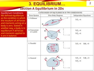
Equilibrium Conditions
We defined equilibrium
as the condition in which
the resultant of all forces
and moments acting on a
body is zero. Stated in
another way, a body is in
equilibrium if all forces
and moments applied to
it are in balance.
2
3.
3. EQUILIBRIUM…
SECTION AEQUILIBRIUM IN TWO DIMENSIONS
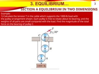
Example:
1) Calculate the tension T in the cable which supports the 1000-lb load with
the pulley arrangement shown. Each pulley is free to rotate about its bearing, and the
weights of all parts are small compared with the load. Find the magnitude of the total
force on the bearing of pulley C.
3
4.
3. EQUILIBRIUM…
SECTION AEQUILIBRIUM IN TWO DIMENSIONS
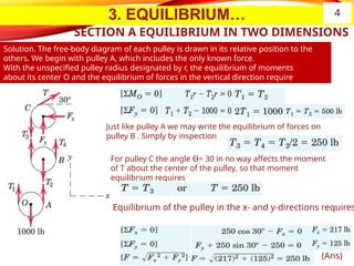
Solution. The free-body diagram of each pulley is drawn in its relative position to the
others. We begin with pulley A, which includes the only known force.
With the unspecified pulley radius designated by r, the equilibrium of moments
about its center O and the equilibrium of forces in the vertical direction require
Just like pulley A we may write the equilibrium of forces on
pulley B . Simply by inspection
For pulley C the angle Ɵ= 30 in no way affects the moment
of T about the center of the pulley, so that moment
equilibrium requires
Equilibrium of the pulley in the x- and y-directions requires
(Ans)
4
3. EQUILIBRIUM…
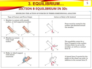
SECTION BEQUILIBRIUM IN 3Ds…
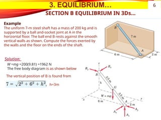
Example
The uniform 7-m steel shaft has a mass of 200 kg and is
supported by a ball and-socket joint at A in the
horizontal floor. The ball end B rests against the smooth
vertical walls as shown. Compute the forces exerted by
the walls and the floor on the ends of the shaft.
W =mg =200(9.81) =1962 N
The free body diagram is as shown below
Solution:
The vertical position of B is found from
h=3m
6
7.
3. EQUILIBRIUM…
SECTION BEQUILIBRIUM IN 3Ds…
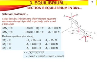
Solution: continued …
Scalar solution: Evaluating the scalar moment equations
about axes through A parallel, respectively, to the x- and
y-axes, gives
7
8.
3. EQUILIBRIUM…
SECTION BEQUILIBRIUM IN 3Ds…
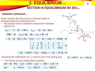
Solution: continued …
Vector solution: We will use A as a moment center to
eliminate reference to the forces at A.
• The position vectors needed to compute the moments
about A are
Equating the coefficients of i, j, and k to zero and solving give
The forces at A are easily determined by
8
9.
4. ANALYSIS OFSIMPLE STRUCTURES
Introduction
͏ In this chaper, we focus on the determination of the forces internal to a
structure—that is, forces of action and reaction between the connected
members.
͏ An engineering structure is any connected system of members built to
support or transfer forces and to safely withstand the loads applied to it.
͏ To determine the forces internal to an engineering structure, we must
dismember the structure and analyze separate free-body diagrams of
individual members or combinations of members.
͏ This analysis requires careful application of Newton’s third law, which states
that each action is accompanied by an equal and opposite reaction.
͏ we analyze the internal forces acting in several types of structures—namely, trusses,
frames, and machines. In this treatment
͏ we consider only statically determinate structures, which do not have more supporting
constraints than are necessary to maintain an equilibrium configuration. Thus, as we
have already seen, the equations of equilibrium are adequate to determine all
unknown reactions.
9
10.
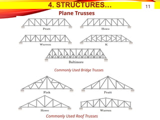
4. STRUCTURES …
PlaneTrusses
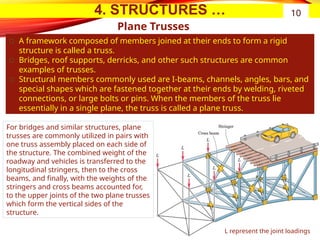
͏ A framework composed of members joined at their ends to form a rigid
structure is called a truss.
͏ Bridges, roof supports, derricks, and other such structures are common
examples of trusses.
͏ Structural members commonly used are I-beams, channels, angles, bars, and
special shapes which are fastened together at their ends by welding, riveted
connections, or large bolts or pins. When the members of the truss lie
essentially in a single plane, the truss is called a plane truss.
10
For bridges and similar structures, plane
trusses are commonly utilized in pairs with
one truss assembly placed on each side of
the structure. The combined weight of the
roadway and vehicles is transferred to the
longitudinal stringers, then to the cross
beams, and finally, with the weights of the
stringers and cross beams accounted for,
to the upper joints of the two plane trusses
which form the vertical sides of the
structure.
L represent the joint loadings
4. STRUCTURES…
Plane Trusses…
SimpleTruss
12
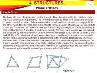
The basic element of a plane truss is the triangle. Three bars joined by pins at their ends,
Fig. 4/3a, constitute a rigid frame. The term rigid is used to mean non-collapsible and also
to mean that deformation of the members due to induced internal strains is negligible. On
the other hand, four or more bars pin-jointed to form a polygon of as many sides constitute
a nonrigid frame. We can make the nonrigid frame in Fig. 4/3b rigid, or stable, by adding a
diagonal bar joining A and D or B and C and thereby forming two triangles. We can extend
the structure by adding additional units of two end-connected bars, such as DE and CE or AF
and DF, Fig. 4/3c, which are pinned to two fixed joints. In this way the entire structure will
remain rigid. Structures built from a basic triangle in the manner described are known as
simple trusses. When more members are present than are needed to prevent collapse, the
truss is statically indeterminate. A statically indeterminate truss cannot be analyzed by the
equations of equilibrium alone. Additional members or supports which are not necessary
for maintaining the equilibrium configuration are called redundant.
13.
4. STRUCTURES…
Plane Trusses…
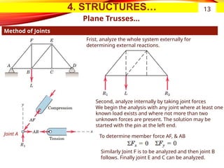
Methodof Joints
13
To determine member force AF, & AB
Joint A
Similarly Joint F is to be analyzed and then joint B
follows. Finally joint E and C can be analyzed.
Second, analyze internally by taking joint forces
We begin the analysis with any joint where at least one
known load exists and where not more than two
unknown forces are present. The solution may be
started with the pin at the left end.
Frist, analyze the whole system externally for
determining external reactions.
14.
4. STRUCTURES…
Plane Trusses…
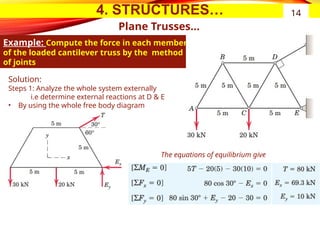
Example:Compute the force in each member
of the loaded cantilever truss by the method
of joints
14
Solution:
Steps 1: Analyze the whole system externally
i.e determine external reactions at D & E
• By using the whole free body diagram
The equations of equilibrium give
15.
4. STRUCTURES…
Plane Trusses…
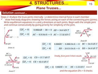
Solutioncontinued …
15
Steps 2: Analyze the truss joints internally i.e determine internal force in each member
draw free-body diagrams showing the forces acting on each of the connecting pins (joints).
Write equilibrium equations in x and y directions at each joints. Begin with the simple joint
and continue consecutively by giving priority for simplicity of the joint.
Finally, from joint E there results
and the equation ΣFx = 0 checks
16.
4. STRUCTURES…
Plane Trusses…
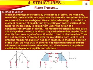
Methodof Section
͏ When analyzing plane trusses by the method of joints, we need only
two of the three equilibrium equations because the procedures involve
concurrent forces at each joint. We can take advantage of the third or
moment equation of equilibrium by selecting an entire section of the
truss for the free body in equilibrium under the action of a
nonconcurrent system of forces. This method of sections has the basic
advantage that the force in almost any desired member may be found
directly from an analysis of a section which has cut that member. Thus,
it is not necessary to proceed with the calculation from joint to joint
until the member in question has been reached. In choosing a section
of the truss, we note that, in general, not more than three members
whose forces are unknown should be cut, since there are only three
available independent equilibrium relations.
16
17.
4. STRUCTURES…
Plane Trusses…
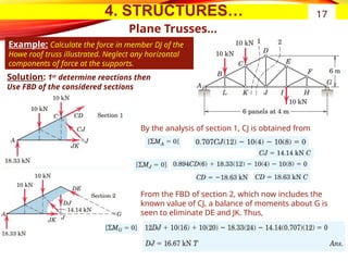
Example:Calculate the force in member DJ of the
Howe roof truss illustrated. Neglect any horizontal
components of force at the supports.
17
By the analysis of section 1, CJ is obtained from
From the FBD of section 2, which now includes the
known value of CJ, a balance of moments about G is
seen to eliminate DE and JK. Thus,
Solution: 1st
determine reactions then
Use FBD of the considered sections
18.
4. STRUCTURES…
Frames andmachines
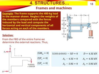
Example: The frame supports the 400-kg load
in the manner shown. Neglect the weights of
the members compared with the forces
induced by the load and compute the
horizontal and vertical components of all
forces acting on each of the members.
18
From the FBD of the entire frame we
determine the external reactions. Thus,
Solution:
19.
4. STRUCTURES…
Frames andmachines
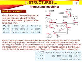
Solution: continued…
19
The solution may proceed by use of a
moment equation about B or E for
member BF, followed by the two force
equations. Thus,
Positive numerical values of the unknowns mean that we assumed their directions correctly
on the free-body diagrams. The value of Cx = Ex = 13.08 kN obtained by inspection of the
free-body diagram of CE is now entered onto the diagram for AD, along with the values of Bx
and By just determined. The equations of equilibrium may now be applied to member AD as
a check, since all the forces acting on it have already been computed. The equations give
20.
5. INTERNAL ACTIONSIN BEAMS
Introduction
͏ Beams are structural members which offer resistance to bending due
to applied loads. Most beams are long prismatic bars, and the loads are
usually applied normal to the axes of the bars.
͏ Beams are undoubtedly the most important of all structural members,
so it is important to understand the basic theory underlying their
design.
͏ To analyze the load-carrying capacities of a beam we must first
establish the equilibrium requirements of the beam as a whole and any
portion of it considered separately.
͏ Second, we must establish the relations between the resulting forces
and the accompanying internal resistance of the beam to support these
forces. The first part of this analysis requires the application of the
principles of statics. The second part involves the strength
characteristics of the material and is usually treated in studies of the
mechanics of solids or the mechanics of materials(i.e an other course).
20
21.
5. BEAMS…
Types ofbeams
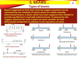
͏ Beams supported so that their external support reactions can be
calculated by the methods of statics alone are called statically
determinate beams. A beam which has more supports than needed to
provide equilibrium is statically indeterminate. To determine the
support reactions for such a beam we must consider its load-
deformation properties in addition to the equations of static
equilibrium.
21
Compound beam (one example)
Overhanging beam
Simply supported beams
(simple beams)
22.
5. BEAMS…
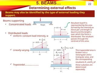
͏ Beamsmay also be identified by the type of external loading they
support.
22
• Concentrated loads
• Distributed loads
Uniform: constant load intensity, w
Linearly varying
Trapezoidal………………….
Beams supporting
Resultant load R is
represented by the area
formed by the intensity w
(force per unit length of
beam) and the length L
over which the force is
distributed. The resultant
passes through the
centroid of this area.
The trapezoidal area is
broken into a
rectangular and a
triangular area, and
the corresponding
resultants R1 and R2 of
these subareas are
determined
separately.
Determining external effects
23.
5. BEAMS…
Determining externaleffects...
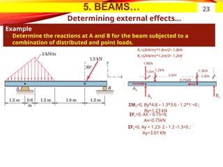
Example
͏ Determine the reactions at A and B for the beam subjected to a
combination of distributed and point loads.
23
By
AX
Ay
1.3kN
0.75kN
R1=(2kN/m)*1.8m/2= 1.8kN
R2=(2kN/m)*1.2m/2= 1.2kN
1.8kN
1.2kN
1.2m
2.6m
ΣMA=0, By*4.8 – 1.3*3.6 - 1.2*1 =0 ;
By=1.23 kN
ΣFx=0, Ax – 0.75=0;
Ax=0.75kN
ΣFy=0, Ay + 1.23- 2 - 1.2 -1.3=0 ;
Ay=3.07 KN
1.0m
24.
5. BEAMS…
Determining internaleffects
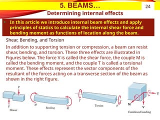
• In this article we introduce internal beam effects and apply
principles of statics to calculate the internal shear force and
bending moment as functions of location along the beam.
24
Shear, Bending, and Torsion
In addition to supporting tension or compression, a beam can resist
shear, bending, and torsion. These three effects are illustrated in
Figures below. The force V is called the shear force, the couple M is
called the bending moment, and the couple T is called a torsional
moment. These effects represent the vector components of the
resultant of the forces acting on a transverse section of the beam as
shown in the right figure.
25.
5. BEAMS…
Determining internaleffects …
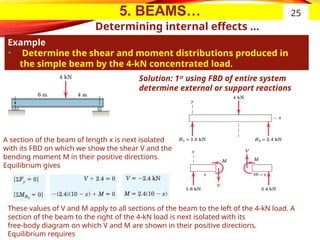
Example
• Determine the shear and moment distributions produced in
the simple beam by the 4-kN concentrated load.
25
Solution: 1st
using FBD of entire system
determine external or support reactions
A section of the beam of length x is next isolated
with its FBD on which we show the shear V and the
bending moment M in their positive directions.
Equilibrium gives
These values of V and M apply to all sections of the beam to the left of the 4-kN load. A
section of the beam to the right of the 4-kN load is next isolated with its
free-body diagram on which V and M are shown in their positive directions.
Equilibrium requires
26.
5. BEAMS…
Shear andmoment diagrams
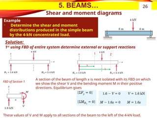
Example
• Determine the shear and moment
distributions produced in the simple beam
by the 4-kN concentrated load.
26
Solution:
1st
using FBD of entire system determine external or support reactions
A section of the beam of length x is next isolated with its FBD on which
we show the shear V and the bending moment M in their positive
directions. Equilibrium gives
These values of V and M apply to all sections of the beam to the left of the 4-kN load.
x
x
1 2
FBD of Section 1
27.
5. BEAMS…
Shear andmoment diagrams…
Solution: continued…
27
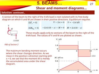
A section of the beam to the right of the 4-kN load is next isolated with its free-body
diagram on which V and M are shown in their positive directions. Equilibrium requires
FBD of Section 2
These results apply only to sections of the beam to the right of the
4-kN load. The values of V and M are plotted as shown.
The maximum bending moment occurs
where the shear changes direction. As we
move in the positive x-direction starting with
x = 0, we see that the moment M is merely
the accumulated area under the shear
diagram.
28.
5. BEAMS…
Shear andmoment diagrams…
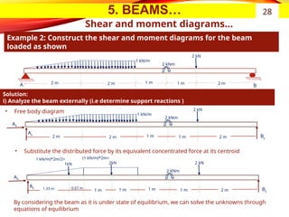
Example 2: Construct the shear and moment diagrams for the beam
loaded as shown
28
1 kN/m
2 kNm
2 kN
B
A 1 m 1 m
2 m 2 m
2 m
1 kN/m
2 kNm
2 kN
By
1 m 1 m
2 m 2 m
2 m
Solution:
i) Analyze the beam externally (i.e determine support reactions )
Ay
AX
• Free body diagram
(1 kN/m)*2m=
2kN
2 kNm
2 kN
By
1 m 1 m
1 m 2 m
0.67 m
Ay
AX
• Substitute the distributed force by its equivalent concentrated force at its centroid
1 m
1.33 m
1 kN/m)*2m/2=
1kN
By considering the beam as it is under state of equilibrium, we can solve the unknowns through
equations of equilibrium
29.
5. BEAMS…
Shear andmoment diagrams…
Example 2: solution …
29
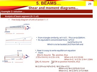
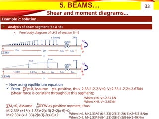
Analysis of beam segment (0< X 2)
≤
• Free body diagram of LHS of section 1---1
x
• From triangle similarity, w/1=x/2 ; Thus w=(x/2)kN/m.
• Its equivalent concentrated force =w*x/2
=(x/2)*(x/2)=x2
/4
Which is to be located 2x/3 from left end
V M
w (kN/m)
x
2.33kN
V M
X2
/4 kN
w 1
x
2
2.33kN
2x/3 x/3
• Now it is easy to write equilibrium equation
From
∑Fy=0, Assume as positive, thus
2.33-x2
/4-V=0, V=2.33- x2
/4;
∑MA=0, Assume CCW as positive moment, thus
M-2.33*x+(x2
/4)*x/3=0; M=2.33x-x3
/12
When x=0, V=2.33 kN
When X=2, V=2.33- 22
/4=1.33kN
When x=0, M=2.33*0-03
/12=0
When X=2, M=2.33*2- 23
/12=4kN
30.
5. BEAMS…
Shear andmoment diagrams…
Example 2: solution …
30
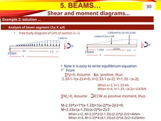
Analysis of beam segment (2 X 4)
≤ ≤
• Free body diagram of LHS of section 2---2
x
V M
1 (kN/m)
2.33kN
• Now it is easy to write equilibrium equation
From
∑Fy=0, Assume as positive, thus
2.33-1-1(x-2)-V=0, V=2.33-1-(x-2); V=1.33 - (x-2);
∑MA=0, Assume CCW as positive moment, thus
M-2.33*x+1*(x-1.33)+1(x-2)*(x-2)/2=0;
M=2.33x-(x-1.33)-(x-2)*(x-2)/2
When x=2, V=1.33 kN
When X=4, V=1.33 - (4-2)=-0.67kN
When x=2, M=2.33*2-(2-1.33)-(2-2)*(2-2)/2=4kNm
When X=4, M=2.33*4-(4-1.33)-(4-2)*(4-2)/2=4.65kNm
2m x-2
x
V M
2.33kN
1.33m x-2
(1kN/m)*(x-2)=1(X-2) kN
(1kN/m)*2m=1 kN
0.67m
31.
5. BEAMS…
Shear andmoment diagrams…
Example 2: solution …
31
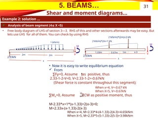
Analysis of beam segment (4 X <5)
≤
• Free body diagram of LHS of section 3---3. RHS of this and other sections afterwards may be easy. But
lets use LHS for all of them. You can check by using RHS
x
V
M
1 (kN/m)
2.33kN
• Now it is easy to write equilibrium equation
From
∑Fy=0, Assume as positive, thus
2.33-1-2-V=0, V=2.33-1-2=-0.67kN
(Shear force is constant throughout this segment);
∑MA=0, Assume CCW as positive moment, thus
M-2.33*x+1*(x-1.33)+2(x-3)=0;
M=2.33x-(x-1.33)-2(x-3)
When x=4, V=-0.67 kN
When X=5, V=-0.67kN
When x=4, M=2.33*4-(4-1.33)-2(4-3)=4.65kNm
When X=5, M=2.33*5-(5-1.33)-2(5-3)=3.98kNm
2m 2m
x
V
M
2.33kN
1.33m 1m
(1kN/m)*(2m)=2 kN
(1kN/m)*2m=1 kN
0.67m x-3
32.
5. BEAMS…
Shear andmoment diagrams…
Example 2: solution …
32
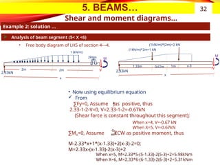
Analysis of beam segment (5< X <6)
• Free body diagram of LHS of section 4---4.
x
V
M
1 (kN/m)
2.33kN
• Now using equilibrium equation
From
∑Fy=0, Assume as positive, thus
2.33-1-2-V=0, V=2.33-1-2=-0.67kN
(Shear force is constant throughout this segment);
∑MA=0, Assume CCW as positive moment, thus
M-2.33*x+1*(x-1.33)+2(x-3)-2=0;
M=2.33x-(x-1.33)-2(x-3)+2
When x=4, V=-0.67 kN
When X=5, V=-0.67kN
When x=5, M=2.33*5-(5-1.33)-2(5-3)+2=5.98kNm
When X=6, M=2.33*6-(6-1.33)-2(6-3)+2=5.31kNm
2m 2m
x
V
M
2.33kN
1.33m 1m
(1kN/m)*(2m)=2 kN
(1kN/m)*2m=1 kN
0.67m x-3
2kNm
33.
5. BEAMS…
Shear andmoment diagrams…
Example 2: solution …
33
Analysis of beam segment (6< X <8)
• Free body diagram of LHS of section 5---5
x
V
M
1 (kN/m)
2.33kN
• Now using equilibrium equation
From Fy=0, Assume as positive, thus 2.33-1-2-2-V=0, V=2.33-1-2-2=-2.67kN
∑
(Shear force is constant throughout this segment);
∑MA=0, Assume CCW as positive moment, thus
M-2.33*x+1*(x-1.33)+2(x-3)-2+2(x-6)=0;
M=2.33x-(x-1.33)-2(x-3)-2(x-6)+2
When x=6, V=-2.67 kN
When X=8, V=-2.67kN
When x=6, M=2.33*6-(6-1.33)-2(6-3)-2(6-6)+2=5.31kNm
When X=8, M=2.33*8-(8-1.33)-2(8-3)-2(8-6)+2=0kNm
2m 2m
2kNm
2 kN
1m 1m
x
V
M
2 kN
1.33m 1m
2kNm
2 kN
1m 1m
1 kN
0.67m 1m
2.33kN
34.
5. BEAMS…
Shear andmoment diagrams…
Example 2: solution …
34
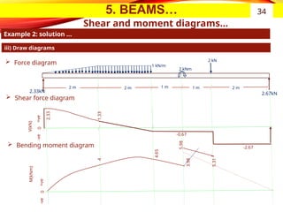
iii) Draw diagrams
1 kN/m
2 kNm
2 kN
2.67kN
1 m 1 m
2 m 2 m
2 m
Force diagram
Shear force diagram
Bending moment diagram
2.33
0
-2.67
1.33
-0.67
2.33kN
4
3.98
5.98
5.31
4.65
+ve
-ve
V(kN)
M(kNm)
0
+ve
-ve
35.
5. BEAMS…
Shear andmoment diagrams…
Example 2: Solution …
35
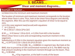
iv) Determine the minimum and maximum moment
The location of minimum and maximum moment corresponds to the location
where shear force is zero. Thus, look at the shear force diagram and identify
the segment. After this use the segment`s equation of shear to be equal to
zero.
i.e in this case segment two(2 x 4) with equations
≤ ≤
V=1.33-(x-2)
M=2.33x-(x-1.33)-(x-2)*(x-2)/2
@ M max, , V=0 hence 1.33-(x-2)=0 , x=3.33m from left is the location
Where shear force is zero and corresponding maximum moment in this
segement.
Substituting x=3.33m in the moment equation gives the maximum moment as
Mmax=2.33*3.33-(3.33-1.33)-(3.33-2)*(3.33-2)/2
=7.76-2-0.88; Mmax=4.88kNm in segment two. But look at the
BMD, due to presence of CW concentrated moment at X=3, The BMD rises by
that amount resulting in the maximum moment through out the beam. Thus
Mmax=5.98 kNm
Mmin=0 by inspection, at the both in ends of the beam
36.
6. CENTROIDS
Introduction
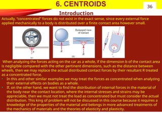
Actually, “concentrated”forces do not exist in the exact sense, since every external force
applied mechanically to a body is distributed over a finite contact area however small.
When analyzing the forces acting on the car as a whole, if the dimension b of the contact area
is negligible compared with the other pertinent dimensions, such as the distance between
wheels, then we may replace the actual distributed contact forces by their resultant R treated
as a concentrated force.
• In this and other similar examples we may treat the forces as concentrated when analyzing
their external effects on bodies as a whole.
• If, on the other hand, we want to find the distribution of internal forces in the material of
the body near the contact location, where the internal stresses and strains may be
appreciable, then we must not treat the load as concentrated but must consider the actual
distribution. This king of problem will not be discussed in this course because it requires a
knowledge of the properties of the material and belongs in more advanced treatments of
the mechanics of materials and the theories of elasticity and plasticity.
36
37.
6. CENTROIDS
Introduction
When forcesare applied over a region whose dimensions are not negligible
compared with other pertinent dimensions, then we must account for the actual
manner in which the force is distributed by summing up the effects of the
distributed force over the entire region. We carry out this process by using the
procedures of mathematical integration.
For this purpose we need to know the intensity of the force at any location. There are three
categories into which such problems fall;
37
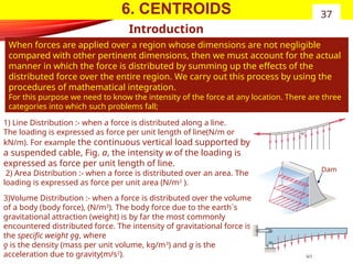
1) Line Distribution :- when a force is distributed along a line.
The loading is expressed as force per unit length of line(N/m or
kN/m). For example the continuous vertical load supported by
a suspended cable, Fig. a, the intensity w of the loading is
expressed as force per unit length of line.
2) Area Distribution :- when a force is distributed over an area. The
loading is expressed as force per unit area (N/m2
).
3)Volume Distribution :- when a force is distributed over the volume
of a body (body force), (N/m3
). The body force due to the earth`s
gravitational attraction (weight) is by far the most commonly
encountered distributed force. The intensity of gravitational force is
the specific weight ƍg, where
ƍ is the density (mass per unit volume, kg/m3
) and g is the
acceleration due to gravity(m/s2
).
Dam
38.
6. CENTROIDS…
Center ofMass Vs. Centre of gravity
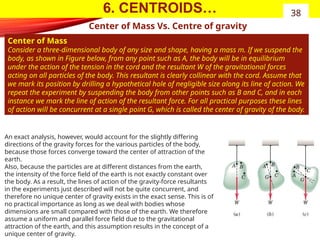
Center of Mass
Consider a three-dimensional body of any size and shape, having a mass m. If we suspend the
body, as shown in Figure below, from any point such as A, the body will be in equilibrium
under the action of the tension in the cord and the resultant W of the gravitational forces
acting on all particles of the body. This resultant is clearly collinear with the cord. Assume that
we mark its position by drilling a hypothetical hole of negligible size along its line of action. We
repeat the experiment by suspending the body from other points such as B and C, and in each
instance we mark the line of action of the resultant force. For all practical purposes these lines
of action will be concurrent at a single point G, which is called the center of gravity of the body.
38
An exact analysis, however, would account for the slightly differing
directions of the gravity forces for the various particles of the body,
because those forces converge toward the center of attraction of the
earth.
Also, because the particles are at different distances from the earth,
the intensity of the force field of the earth is not exactly constant over
the body. As a result, the lines of action of the gravity-force resultants
in the experiments just described will not be quite concurrent, and
therefore no unique center of gravity exists in the exact sense. This is of
no practical importance as long as we deal with bodies whose
dimensions are small compared with those of the earth. We therefore
assume a uniform and parallel force field due to the gravitational
attraction of the earth, and this assumption results in the concept of a
unique center of gravity.
39.
6. CENTROIDS…
Center ofMass Vs. Centre of gravity…
As it can be seen from the above equations, the formulas are independent of
gravitational effects since g no longer appears. They therefore define a unique
point in the body which is a function solely of the distribution of mass. This point
is called the center of mass, and clearly it coincides with the center of gravity as
long as the gravity field is treated as uniform and parallel.
It is meaningless to speak of the center of gravity of a body which is removed from
the gravitational field of the earth, since no gravitational forces would act on it.
The body would, however, still have its unique center of mass. We will usually refer
henceforth to the center of mass rather than to the center of gravity. Also, the
center of mass has a special significance in calculating the dynamic response of a
body to unbalanced forces.
In most problems the calculation of the position of the center of mass may be
simplified by an intelligent choice of reference axes. In general the axes should be
placed so as to simplify the equations of the boundaries as much as possible. Thus,
polar coordinates will be useful for bodies with circular boundaries. Another
important clue may be taken from considerations of symmetry. Whenever there
exists a line or plane of symmetry in a homogeneous body, a coordinate axis or
plane should be chosen to coincide with this line or plane. The center of mass will
always lie on such a line or plane, since the moments due to symmetrically located
elements will always cancel, and the body may be considered composed of pairs of
these elements.
39
In summary…
40.
6. CENTROIDS…
Choice ofElement for Integration
With mass centers and centroids the concept of the moment principle is simple
enough; the difficult steps are the choice of the differential element and setting
up the integrals. The following five guidelines will be useful.
40
Centroids of Lines, Areas, and Volumes…
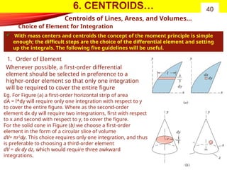
1. Order of Element
Whenever possible, a first-order differential
element should be selected in preference to a
higher-order element so that only one integration
will be required to cover the entire figure
Eg. For Figure (a) a first-order horizontal strip of area
dA = l*dy will require only one integration with respect to y
to cover the entire figure. Where as the second-order
element dx dy will require two integrations, first with respect
to x and second with respect to y, to cover the figure.
For the solid cone in Figure (b) we choose a first-order
element in the form of a circular slice of volume
dV= πr2
dy. This choice requires only one integration, and thus
is preferable to choosing a third-order element
dV = dx dy dz, which would require three awkward
integrations.
41.
6. CENTROIDS…
Choice ofElement for Integration…
41
Centroids of Lines, Areas, and Volumes…
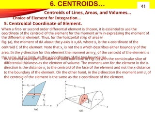
5. Centroidal Coordinate of Element.
When a first- or second order differential element is chosen, it is essential to use the
coordinate of the centroid of the element for the moment arm in expressing the moment of
the differential element. Thus, for the horizontal strip of area in
Fig. (a), the moment of dA about the y-axis is xcdA, where xc is the x-coordinate of the
centroid C of the element. Note that xc is not the x which describes either boundary of the
area. In the y-direction for this element the moment arm yc of the centroid of the element is
the same, in the limit, as the y-coordinates of the two boundaries.
As a second example, consider the solid half-cone of Fig. (b) with the semicircular slice of
differential thickness as the element of volume. The moment arm for the element in the x-
direction is the distance xc to the centroid of the face of the element and not the x-distance
to the boundary of the element. On the other hand, in the z-direction the moment arm zc of
the centroid of the element is the same as the z-coordinate of the element.
42.
6. CENTROIDS…
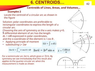
Examples 2
42
Centroidsof Lines, Areas, and Volumes…
Locate the centroid of a circular arc as shown in
the figure
Solution: polar coordinates are preferable to
rectangular coordinates to express the length of a
circular arc.
Choosing the axis of symmetry as the x-axis makes y=0.
A differential element of arc has the length
dL = rdθ expressed in polar coordinates,
and the x-coordinate of the element is r cos θ .
• Applying principle of moment
• substituting L= 2αr
For a semicircular arc 2α=π, which gives x= 2r/π. By
symmetry we see immediately that this result also
applies to the quarter-circular arc when the
measurement is made as shown
43.
6. CENTROIDS…
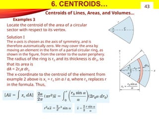
Examples 3
43
Centroidsof Lines, Areas, and Volumes…
Locate the centroid of the area of a circular
sector with respect to its vertex.
Solution I
The x-axis is chosen as the axis of symmetry, and is
therefore automatically zero. We may cover the area by
moving an element in the form of a partial circular ring, as
shown in the figure, from the center to the outer periphery.
The radius of the ring is r0 and its thickness is dr0, so
that its area is
dA = 2r0α dr0
The x-coordinate to the centroid of the element from
example 2 above is xc = r0 sin α / α, where r0 replaces r
in the formula. Thus,
44.
6. CENTROIDS…
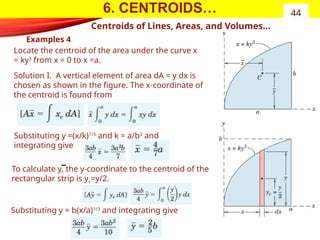
Examples 4
44
Centroidsof Lines, Areas, and Volumes…
Locate the centroid of the area under the curve x
= ky3
from x = 0 to x =a.
Solution I. A vertical element of area dA = y dx is
chosen as shown in the figure. The x-coordinate of
the centroid is found from
Substituting y =(x/k)1/3
and k = a/b3
and
integrating give
Substituting y = b(x/a)1/3
and integrating give
To calculate y, the y-coordinate to the centroid of the
rectangular strip is yc=y/2.
45.
6. CENTROIDS
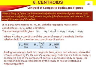
Centroid ofComposite Bodies and Figures
When a body or figure can be conveniently divided into several parts whose mass
centers are easily determined, we use the principle of moments and treat each part
as a finite element of the whole.
45
If Its parts have masses m1, m2, m3 with the respective mass-center
coordinates x1, x2, x3 in the x-direction.
The moment principle gives
Where X is the x-coordinate of the center of mass of the whole. Similar
relations hold for the other two coordinate directions.
Analogous relations hold for composite lines, areas, and volumes, where the
m’s are replaced by L’s, A’s, and V’s, respectively. Note that if a hole or cavity is
considered one of the component parts of a composite body or figure, the
corresponding mass represented by the cavity or hole is treated as a
negative quantity.
46.
6. CENTROIDS…
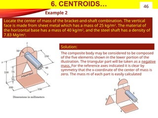
Example 2
Locatethe center of mass of the bracket-and-shaft combination. The vertical
face is made from sheet metal which has a mass of 25 kg/m2
. The material of
the horizontal base has a mass of 40 kg/m2
, and the steel shaft has a density of
7.83 Mg/m3
.
46
Solution:
The composite body may be considered to be composed
of the five elements shown in the lower portion of the
illustration. The triangular part will be taken as a negative
mass. For the reference axes indicated it is clear by
symmetry that the x-coordinate of the center of mass is
zero. The mass m of each part is easily calculated
47.
6. CENTROIDS…
Example 2…
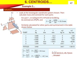
47
•Look at the rectangular coordinate system chosen. Then
calculate mass and centroid for each parts
Solution…
z
x
y
For part 1, m=(25kg/m2
)*3.14*0.052
/2=0.098 kg
Its centroid are x=y=0, and
Similarly calculated for other parts and summarized in the table
shown below
X,Y,Z=(0,53.3,-45.7)mm
…Answer
48.
7. AREA MOMENTOF INERTIA
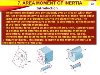
Introduction
When forces are distributed continuously over an area on which they
act, it is often necessary to calculate the moment of these forces about
some axis either in or perpendicular to the plane of the area. The
intensity of the force (pressure or stress) is proportional to the distance
of the force from the moment axis.
The elemental force acting on an element of area, then, is proportional
to distance times differential area, and the elemental moment is
proportional to distance squared times differential area. We see,
therefore that the total moment involves an integral that has the form
∫(distance)2
d(area). This integral is known as the moment of inertia or
the second moment of the area.
48
49.
7. AREA MOMENTOF INERTIA
Introduction
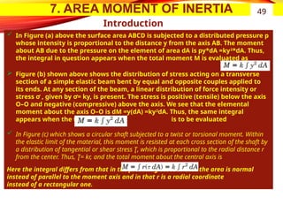
In Figure (a) above the surface area ABCD is subjected to a distributed pressure p
whose intensity is proportional to the distance y from the axis AB. The moment
about AB due to the pressure on the element of area dA is py*dA =ky2
*dA. Thus,
the integral in question appears when the total moment M is evaluated as
Figure (b) shown above shows the distribution of stress acting on a transverse
section of a simple elastic beam bent by equal and opposite couples applied to
its ends. At any section of the beam, a linear distribution of force intensity or
stress ơ , given by ơ= ky, is present. The stress is positive (tensile) below the axis
O–O and negative (compressive) above the axis. We see that the elemental
moment about the axis O–O is dM =y(dA) =ky2
dA. Thus, the same integral
appears when the total moment is to be evaluated
In Figure (c) which shows a circular shaft subjected to a twist or torsional moment. Within
the elastic limit of the material, this moment is resisted at each cross section of the shaft by
a distribution of tangential or shear stress Ʈ, which is proportional to the radial distance r
from the center. Thus, Ʈ= kr, and the total moment about the central axis is
Here the integral differs from that in the preceding cases in that the area is normal
instead of parallel to the moment axis and in that r is a radial coordinate
instead of a rectangular one.
49
50.
7. AREA MOMENTOF INERTIA 50
Rectangular and Polar Moments of Inertia
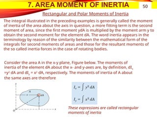
Consider the area A in the x-y plane, Figure below. The moments of
inertia of the element dA about the x- and y-axes are, by definition, dIx
=y2
dA and dIy = x2
dA, respectively. The moments of inertia of A about
the same axes are therefore
These expressions are called rectangular
moments of inertia
The integral illustrated in the preceding examples is generally called the moment
of inertia of the area about the axis in question, a more fitting term is the second
moment of area, since the first moment ydA is multiplied by the moment arm y to
obtain the second moment for the element dA. The word inertia appears in the
terminology by reason of the similarity between the mathematical form of the
integrals for second moments of areas and those for the resultant moments of
the so called inertia forces in the case of rotating bodies.
51.
7. AREA MOMENTOF INERTIA
Transfer of Axes( Parallel axis Theorem)
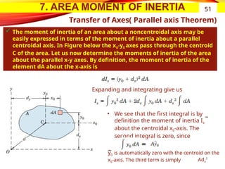
The moment of inertia of an area about a noncentroidal axis may be
easily expressed in terms of the moment of inertia about a parallel
centroidal axis. In Figure below the x0-y0 axes pass through the centroid
C of the area. Let us now determine the moments of inertia of the area
about the parallel x-y axes. By definition, the moment of inertia of the
element dA about the x-axis is
51
Expanding and integrating give us
• We see that the first integral is by
definition the moment of inertia Ix
about the centroidal x0-axis. The
second integral is zero, since
y0 is automatically zero with the centroid on the
x0-axis. The third term is simply Adx
2
52.
7. AREA MOMENTOF INERTIA
Transfer of Axes…
52
Thus, the expression for Ix and the similar expression for Iy become
the sum of these two equations gives
These three equations shown above are the so-called parallel-axis theorems.
Two points in particular should be noted. First, the axes between which the
transfer is made must be parallel, and second, one of the axes must pass
through the centroid of the area.
If a transfer is desired between two parallel axes neither of which passes
through the centroid, it is first necessary to transfer from one axis to the
parallel centroidal axis and then to transfer from the centroidal axis to the
second axis.
The parallel-axis theorems also hold for radii of gyration. With substitution of
the definition of k into equations above, the transfer relation becomes
Where k is the radius of gyration about a centroidal
axis parallel to the axis about which k applies and d is
the distance between the two axes.
53.
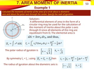
7. AREA MOMENTOF INERTIA
Example 1
Calculate the moments of inertia of the area of a circle about a diametric
axis and about the polar axis through the center. Specify the radii of gyration.
53
Solution:-
A differential element of area in the form of a
circular ring may be used for the calculation of
the moment of inertia about the polar z-axis
through O since all elements of the ring are
equidistant from O. The elemental area is
The polar radius of gyration is
By symmetry Ix = Iy ; using then
The radius of gyration about the diametric axis is
54.
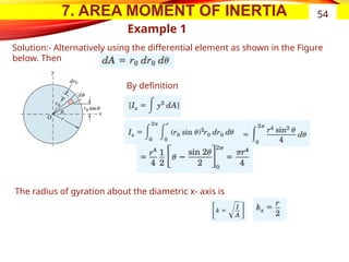
7. AREA MOMENTOF INERTIA
Example 1
54
Solution:- Alternatively using the differential element as shown in the Figure
below. Then
By definition
The radius of gyration about the diametric x- axis is
55.
7. AREA MOMENTOF INERTIA 55
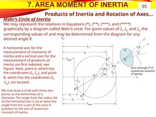
Products of Inertia and Rotation of Axes…
Mohr’s Circle of Inertia
We may represent the relations in Equations (*), (**), (***), and (****)
graphically by a diagram called Mohr’s circle. For given values of Ix, Iy, and Ixy the
corresponding values of and may be determined from the diagram for any
desired angle θ.
A horizontal axis for the
measurement of moments of
inertia and a vertical axis for the
measurement of products of
inertia are first selected, see
Figure. Next, point A, which has
the coordinates (Ix, Ixy), and point
B, which has the coordinates (Iy,
-Ixy), are located.
We now draw a circle with these two
points as the extremities of a
diameter. The angle from the radius OA
to the horizontal axis is 2α or twice the
angle from the x-axis of the area in
question to the axis of maximum
moment of inertia.
56.
7. AREA MOMENTOF INERTIA 56
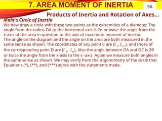
Products of Inertia and Rotation of Axes…
Mohr’s Circle of Inertia
We now draw a circle with these two points as the extremities of a diameter. The
angle from the radius OA to the horizontal axis is 2α or twice the angle from the
x-axis of the area in question to the axis of maximum moment of inertia.
The angle on the diagram and the angle on the area are both measured in the
same sense as shown. The coordinates of any point C are (I`x, Ix`y`), and those of
the corresponding point D are (I`y, -Ixy), Also the angle between OA and OC is 2θ
or twice the angle from the x-axis to the x`-axis. Again we measure both angles in
the same sense as shown. We may verify from the trigonometry of the circle that
Equations (*), (**), and (***) agree with the statements made.
57.
7. AREA MOMENTOF INERTIA 57
Products of Inertia and Rotation of Axes…
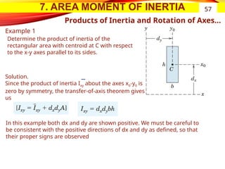
Example 1
Determine the product of inertia of the
rectangular area with centroid at C with respect
to the x-y axes parallel to its sides.
Solution.
Since the product of inertia Ixy about the axes x0-y0 is
zero by symmetry, the transfer-of-axis theorem gives
us
In this example both dx and dy are shown positive. We must be careful to
be consistent with the positive directions of dx and dy as defined, so that
their proper signs are observed
58.
8. FRICTION
Introduction
Inthe preceding chapters we have usually assumed that the forces of
action and reaction between contacting surfaces act normal to the
surfaces. This assumption characterizes the interaction between smooth
surfaces.
Although this ideal assumption often involves only a relatively small error,
there are many problems in which we must consider the ability of
contacting surfaces to support tangential as well as normal forces.
Tangential forces generated between contacting surfaces are called
friction forces and occur to some degree in the interaction between all
real surfaces. Whenever a tendency exists for one contacting surface to
slide along another surface, the friction forces developed are always in a
direction to oppose this tendency.
In some types of machines and processes we want to minimize the retarding effect
of friction forces. Examples are bearings of all types, power screws, gears, the flow
of fluids in pipes, and the propulsion of aircraft and missiles through the
atmosphere.
In other situations we wish to maximize the effects of friction, as in brakes, clutches,
belt drives, and wedges. Wheeled vehicles depend on friction for both starting and
stopping, and ordinary walking depends on friction between the shoe and the
ground.
58
59.
8. FRICTION…
Introduction…
Frictionforces are present throughout nature and exist in all machines no
matter how accurately constructed or carefully lubricated. A machine or
process in which friction is small enough to be neglected is said to be
ideal. When friction must be taken into account, the machine or process is
termed real.
In all cases where there is sliding motion between parts,
o the friction forces result in a loss of energy which is dissipated in the
form of heat.
o Wear is another effect of friction.
59
60.
8. FRICTION…
Types ofFriction
(a) Dry Friction
Dry friction occurs when the unlubricated surfaces of two solids are in contact under a
condition of sliding or a tendency to slide. A friction force tangent to the surfaces of
contact occurs both during the interval leading up to impending slippage and while
slippage takes place. The direction of this friction force always opposes the motion or
impending motion. This type of friction is also called Coulomb friction. The principles of dry
or Coulomb friction were developed largely from the experiments of Coulomb in 1781 and
from the work of Morin from 1831 to 1834. we describe an analytical model sufficient to
handle the vast majority of problems involving dry friction.
(b) Fluid Friction.
Fluid friction occurs when adjacent layers in a fluid (liquid or gas) are moving at different velocities.
This motion causes frictional forces between fluid elements, and these forces depend on the relative
velocity between layers. When there is no relative velocity, there is no fluid friction. Fluid friction
depends not only on the velocity gradients within the fluid but also on the viscosity of the fluid, which is
a measure of its resistance to shearing action between fluid layers. Fluid friction is treated in the study
of fluid mechanics and will not be discussed further in this course.
(c) Internal Friction.
Internal friction occurs in all solid materials which are subjected to cyclical loading. For highly
elastic materials the recovery from deformation occurs with very little loss of energy due to
internal friction. For materials which have low limits of elasticity and which undergo appreciable
plastic deformation during loading, a considerable amount of internal friction may accompany
this deformation. The mechanism of internal friction is associated with the action of shear
deformation, which is discussed in references on materials science.
60
61.
8. FRICTION
Example 1
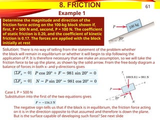
Determinethe magnitude and direction of the
friction force acting on the 100-kg block shown if,
first, P = 500 N and, second, P = 100 N. The coefficient
of static friction is 0.20, and the coefficient of kinetic
friction is 0.17. The forces are applied with the block
initially at rest
61
Solution: There is no way of telling from the statement of the problem whether
the block will remain in equilibrium or whether it will begin to slip following the
application of P. It is therefore necessary that we make an assumption, so we will take the
friction force to be up the plane, as shown by the solid arrow. From the free-body diagram a
balance of forces in both x- and y-directions gives
Case I. P = 500 N
Substitution into the first of the two equations gives
The negative sign tells us that if the block is in equilibrium, the friction force acting
on it is in the direction opposite to that assumed and therefore is down the plane.
But is the surface capable of developing such force? See next slide
62.
8. FRICTION
• Wedges
•Screws
Reading Assignment on problems involving
62
THE END
Thank You
Editor's Notes
#1 Good morning?
Today we will see, …
we will begin with brainstorming questions that such as:…
How could define …?
Why it is important to …?
#2 Good morning?
Today we will see, …
we will begin with brainstorming questions that such as:…
How could define …?
Why it is important to …?
#3 Good morning?
Today we will see, …
we will begin with brainstorming questions that such as:…
How could define …?
Why it is important to …?
#4 Good morning?
Today we will see, …
we will begin with brainstorming questions that such as:…
How could define …?
Why it is important to …?
#5 Good morning?
Today we will see, …
we will begin with brainstorming questions that such as:…
How could define …?
Why it is important to …?
#6 Good morning?
Today we will see, …
we will begin with brainstorming questions that such as:…
How could define …?
Why it is important to …?
#7 Good morning?
Today we will see, …
we will begin with brainstorming questions that such as:…
How could define …?
Why it is important to …?
#8 Good morning?
Today we will see, …
we will begin with brainstorming questions that such as:…
How could define …?
Why it is important to …?
#9 Good morning?
Today we will see, …
we will begin with brainstorming questions that such as:…
How could define …?
Why it is important to …?
#10 Good morning?
Today we will see, …
we will begin with brainstorming questions that such as:…
How could define …?
Why it is important to …?
#11 Good morning?
Today we will see, …
we will begin with brainstorming questions that such as:…
How could define …?
Why it is important to …?
#12 Good morning?
Today we will see, …
we will begin with brainstorming questions that such as:…
How could define …?
Why it is important to …?
#13 Good morning?
Today we will see, …
we will begin with brainstorming questions that such as:…
How could define …?
Why it is important to …?
#14 Good morning?
Today we will see, …
we will begin with brainstorming questions that such as:…
How could define …?
Why it is important to …?
#15 Good morning?
Today we will see, …
we will begin with brainstorming questions that such as:…
How could define …?
Why it is important to …?
#16 Good morning?
Today we will see, …
we will begin with brainstorming questions that such as:…
How could define …?
Why it is important to …?
#17 Good morning?
Today we will see, …
we will begin with brainstorming questions that such as:…
How could define …?
Why it is important to …?
#18 Good morning?
Today we will see, …
we will begin with brainstorming questions that such as:…
How could define …?
Why it is important to …?
#19 Good morning?
Today we will see, …
we will begin with brainstorming questions that such as:…
How could define …?
Why it is important to …?
#20 Good morning?
Today we will see, …
we will begin with brainstorming questions that such as:…
How could define …?
Why it is important to …?
#21 Good morning?
Today we will see, …
we will begin with brainstorming questions that such as:…
How could define …?
Why it is important to …?
#22 Good morning?
Today we will see, …
we will begin with brainstorming questions that such as:…
How could define …?
Why it is important to …?
#23 Good morning?
Today we will see, …
we will begin with brainstorming questions that such as:…
How could define …?
Why it is important to …?
#24 Good morning?
Today we will see, …
we will begin with brainstorming questions that such as:…
How could define …?
Why it is important to …?
#25 Good morning?
Today we will see, …
we will begin with brainstorming questions that such as:…
How could define …?
Why it is important to …?
#26 Good morning?
Today we will see, …
we will begin with brainstorming questions that such as:…
How could define …?
Why it is important to …?
#27 Good morning?
Today we will see, …
we will begin with brainstorming questions that such as:…
How could define …?
Why it is important to …?
#28 Good morning?
Today we will see, …
we will begin with brainstorming questions that such as:…
How could define …?
Why it is important to …?
#29 Good morning?
Today we will see, …
we will begin with brainstorming questions that such as:…
How could define …?
Why it is important to …?
#30 Good morning?
Today we will see, …
we will begin with brainstorming questions that such as:…
How could define …?
Why it is important to …?
#31 Good morning?
Today we will see, …
we will begin with brainstorming questions that such as:…
How could define …?
Why it is important to …?
#32 Good morning?
Today we will see, …
we will begin with brainstorming questions that such as:…
How could define …?
Why it is important to …?
#33 Good morning?
Today we will see, …
we will begin with brainstorming questions that such as:…
How could define …?
Why it is important to …?
#34 Good morning?
Today we will see, …
we will begin with brainstorming questions that such as:…
How could define …?
Why it is important to …?
#35 Good morning?
Today we will see, …
we will begin with brainstorming questions that such as:…
How could define …?
Why it is important to …?
#36 Good morning?
Today we will see, …
we will begin with brainstorming questions that such as:…
How could define …?
Why it is important to …?
#37 Good morning?
Today we will see, …
we will begin with brainstorming questions that such as:…
How could define …?
Why it is important to …?
#38 Good morning?
Today we will see, …
we will begin with brainstorming questions that such as:…
How could define …?
Why it is important to …?
#39 Good morning?
Today we will see, …
we will begin with brainstorming questions that such as:…
How could define …?
Why it is important to …?
#40 Good morning?
Today we will see, …
we will begin with brainstorming questions that such as:…
How could define …?
Why it is important to …?
#41 Good morning?
Today we will see, …
we will begin with brainstorming questions that such as:…
How could define …?
Why it is important to …?
#42 Good morning?
Today we will see, …
we will begin with brainstorming questions that such as:…
How could define …?
Why it is important to …?
#43 Good morning?
Today we will see, …
we will begin with brainstorming questions that such as:…
How could define …?
Why it is important to …?
#44 Good morning?
Today we will see, …
we will begin with brainstorming questions that such as:…
How could define …?
Why it is important to …?
#45 Good morning?
Today we will see, …
we will begin with brainstorming questions that such as:…
How could define …?
Why it is important to …?
#46 Good morning?
Today we will see, …
we will begin with brainstorming questions that such as:…
How could define …?
Why it is important to …?
#47 Good morning?
Today we will see, …
we will begin with brainstorming questions that such as:…
How could define …?
Why it is important to …?
#48 Good morning?
Today we will see, …
we will begin with brainstorming questions that such as:…
How could define …?
Why it is important to …?
#49 Good morning?
Today we will see, …
we will begin with brainstorming questions that such as:…
How could define …?
Why it is important to …?
#50 Good morning?
Today we will see, …
we will begin with brainstorming questions that such as:…
How could define …?
Why it is important to …?
#51 Good morning?
Today we will see, …
we will begin with brainstorming questions that such as:…
How could define …?
Why it is important to …?
#52 Good morning?
Today we will see, …
we will begin with brainstorming questions that such as:…
How could define …?
Why it is important to …?
#53 Good morning?
Today we will see, …
we will begin with brainstorming questions that such as:…
How could define …?
Why it is important to …?
#54 Good morning?
Today we will see, …
we will begin with brainstorming questions that such as:…
How could define …?
Why it is important to …?
#55 Good morning?
Today we will see, …
we will begin with brainstorming questions that such as:…
How could define …?
Why it is important to …?
#56 Good morning?
Today we will see, …
we will begin with brainstorming questions that such as:…
How could define …?
Why it is important to …?
#57 Good morning?
Today we will see, …
we will begin with brainstorming questions that such as:…
How could define …?
Why it is important to …?
#58 Good morning?
Today we will see, …
we will begin with brainstorming questions that such as:…
How could define …?
Why it is important to …?
#59 Good morning?
Today we will see, …
we will begin with brainstorming questions that such as:…
How could define …?
Why it is important to …?
#60 Good morning?
Today we will see, …
we will begin with brainstorming questions that such as:…
How could define …?
Why it is important to …?
#61 Good morning?
Today we will see, …
we will begin with brainstorming questions that such as:…
How could define …?
Why it is important to …?
#62 Good morning?
Today we will see, …
we will begin with brainstorming questions that such as:…
How could define …?
Why it is important to …?


![Lecture truss [compatibility mode]](https://cdn.slidesharecdn.com/ss_thumbnails/lecturetrusscompatibilitymode-160126134009-thumbnail.jpg?width=640&height=640&fit=bounds)


