Downloaded 1,101 times
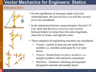
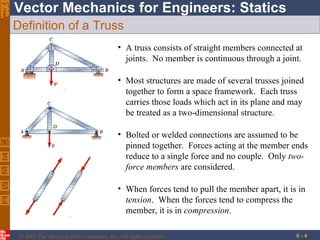
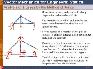
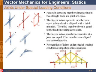
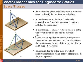
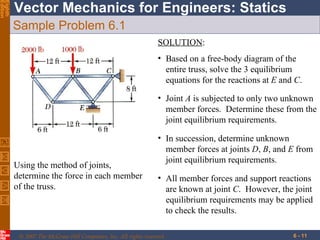
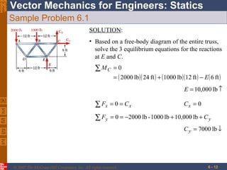
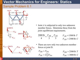
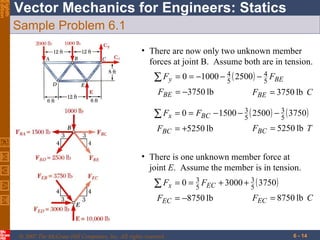
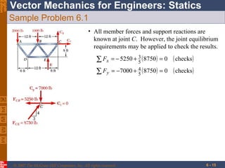
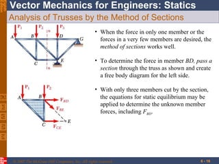
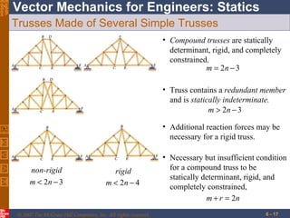
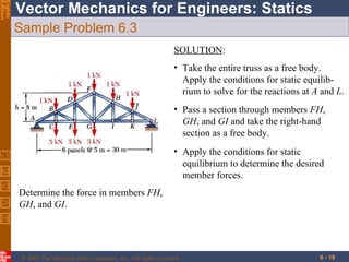
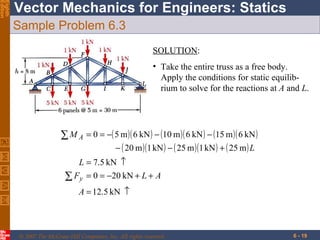
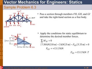
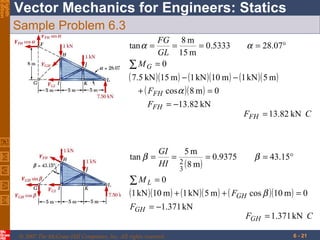
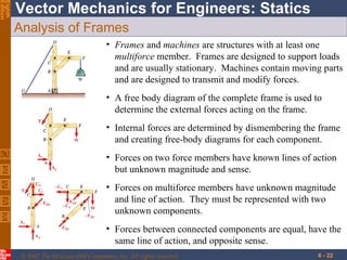
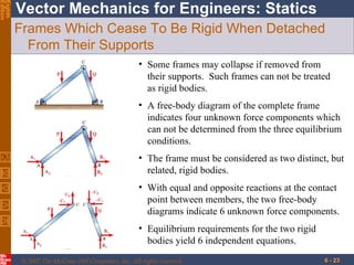
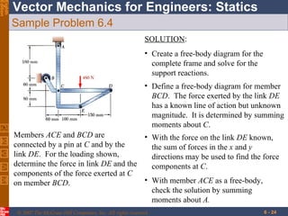
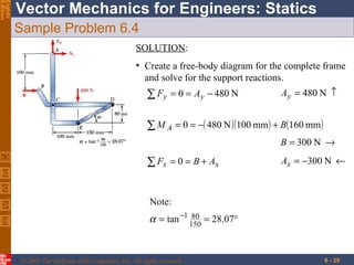
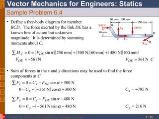
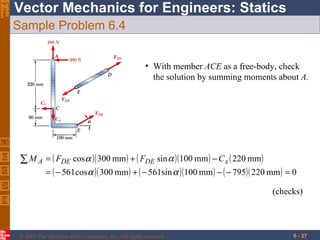

This document discusses the analysis of structures including trusses, frames, and machines. It defines trusses as structures formed from two-force members connected at joints. Trusses can be analyzed using the method of joints or sections. Frames contain multi-force members and may cease to be rigid when detached from supports. Machines are designed to transmit and modify forces and transform input to output forces. Sample problems demonstrate applying equilibrium conditions to determine member forces and reactions.

![THEORY OF STRUCTURES-I [B. ARCH.]](https://cdn.slidesharecdn.com/ss_thumbnails/theoryofstructures-ib-180903021950-thumbnail.jpg?width=640&height=640&fit=bounds)


![Lecture truss [compatibility mode]](https://cdn.slidesharecdn.com/ss_thumbnails/lecturetrusscompatibilitymode-160126134009-thumbnail.jpg?width=640&height=640&fit=bounds)


