Download as PDF, PPTX
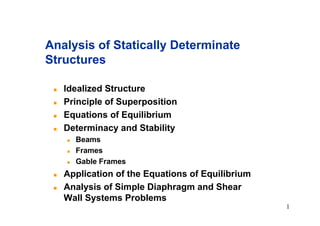
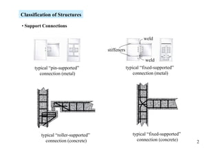
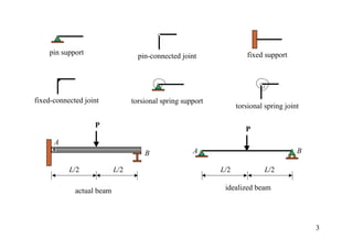
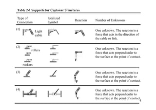
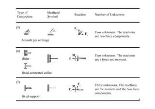
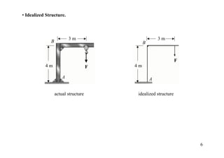
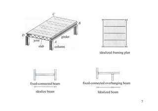
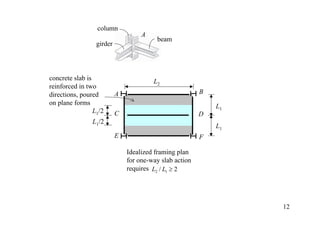
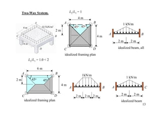
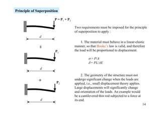
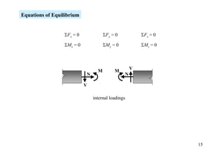
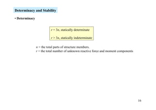
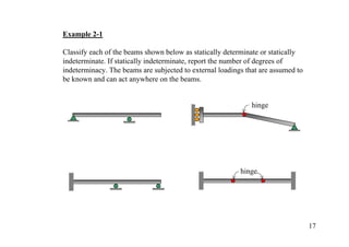
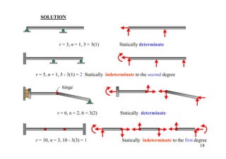
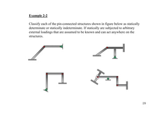
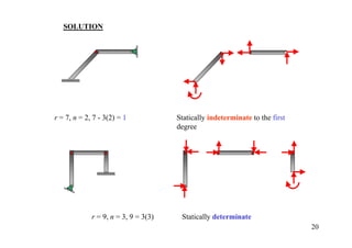
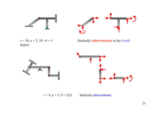
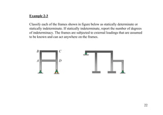
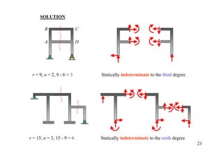
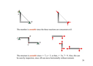
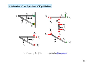
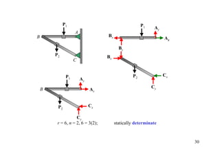
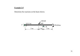
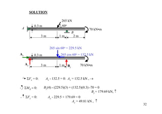
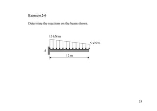
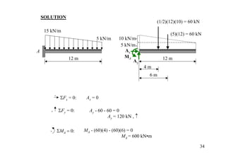
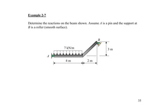
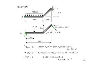
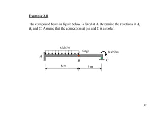
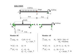
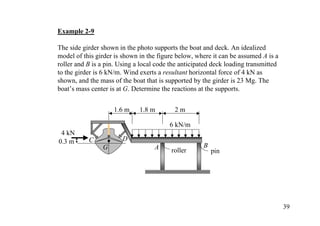
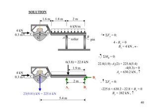
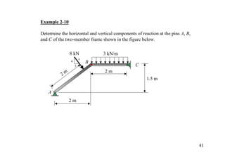
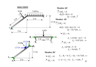
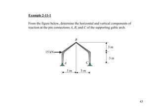
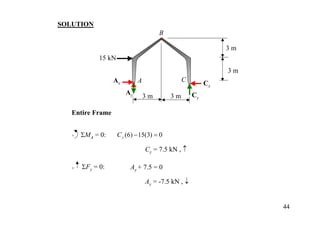
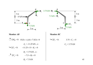
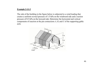
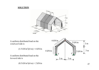
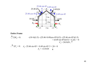
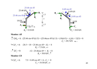
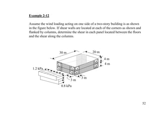
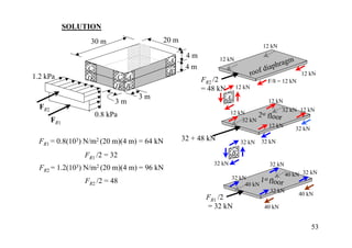
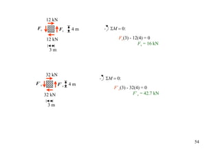

The document discusses the analysis of statically determinate structures, including defining idealized structures, explaining the principle of superposition and equations of equilibrium, classifying structures as determinate or indeterminate, and providing examples of determining reactions on beams and frames through applying the equations of equilibrium.


![Part 1[Autosaved].pptx](https://cdn.slidesharecdn.com/ss_thumbnails/part1autosaved-221102081148-b5d4b037-thumbnail.jpg?width=640&height=640&fit=bounds)