Downloaded 1,404 times


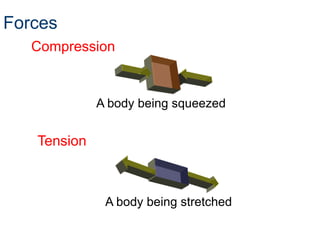
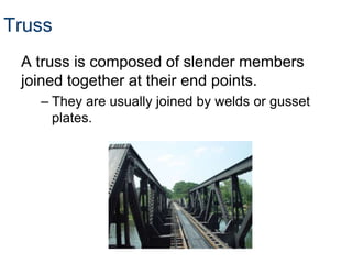
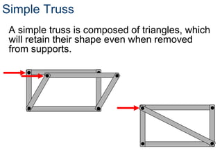
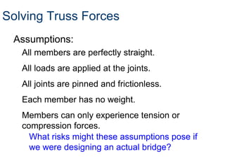
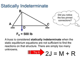
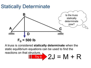
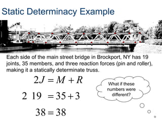
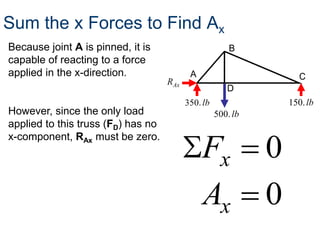
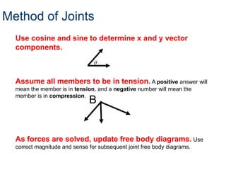
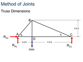
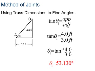
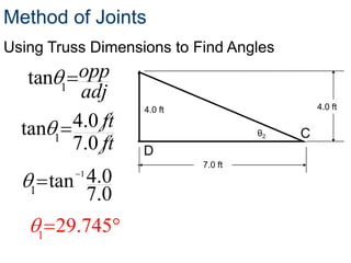
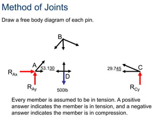
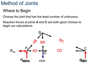
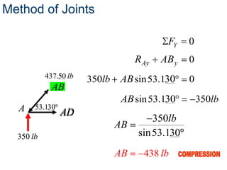
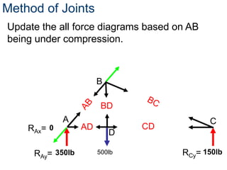
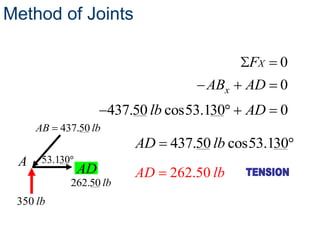
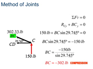
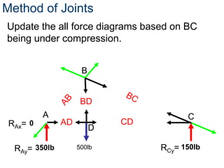
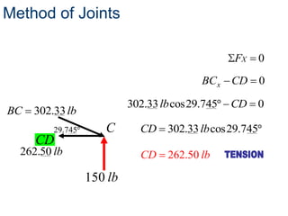
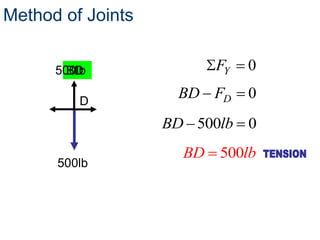

- A truss is a structure composed of slender members joined at their endpoints. Trusses use triangular shapes that retain their form even when supports are removed. - To solve for forces in a truss, assumptions are made that members are straight, loads apply at joints, joints are frictionless pins, members have no weight, and members experience only tension or compression. - The method of joints is used to solve each joint by summing forces and moments. Free body diagrams are drawn and updated as member forces are solved sequentially. - This process begins at a simply supported joint and uses trigonometry and equilibrium equations to calculate member forces throughout the truss.