Downloaded 390 times


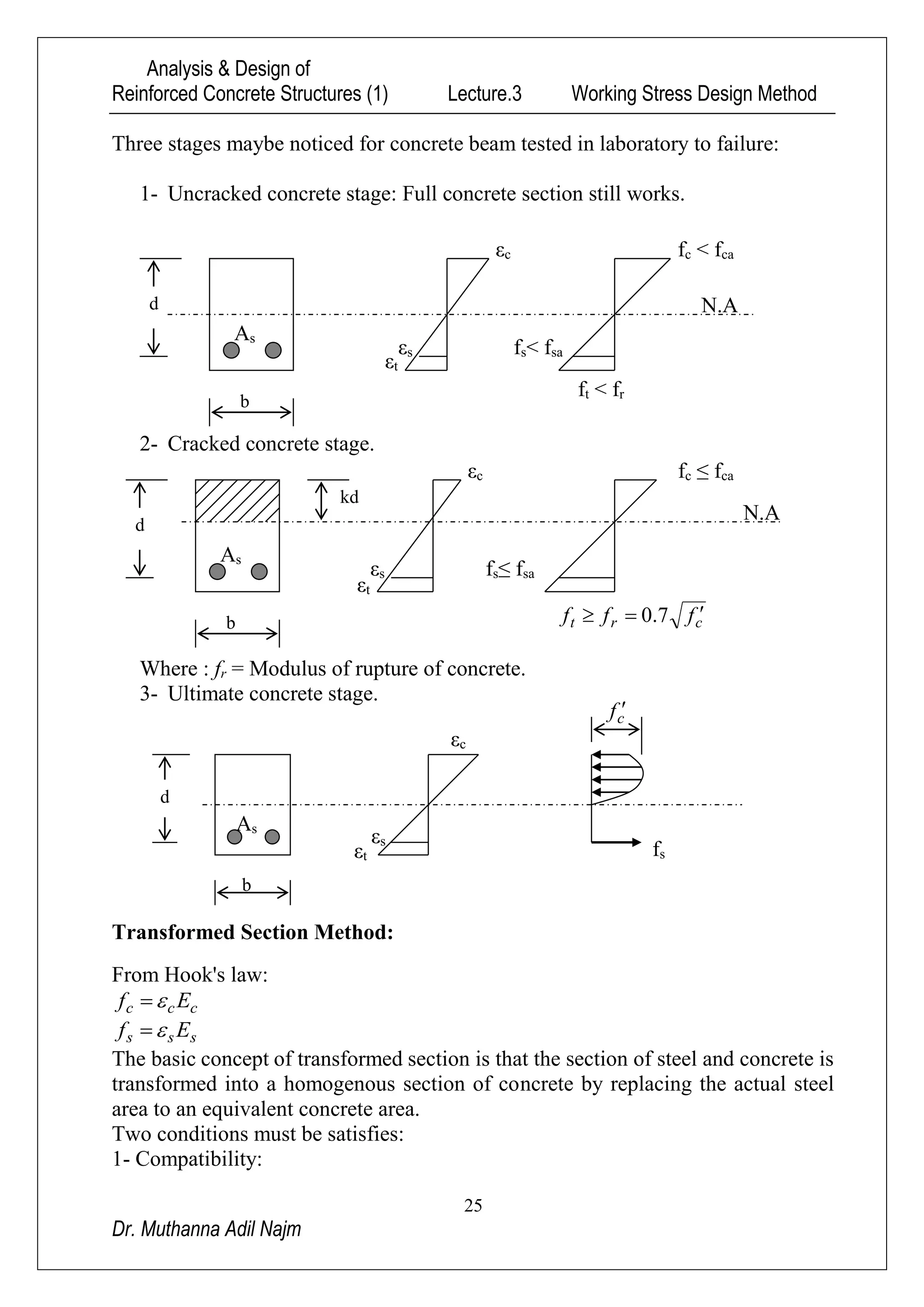
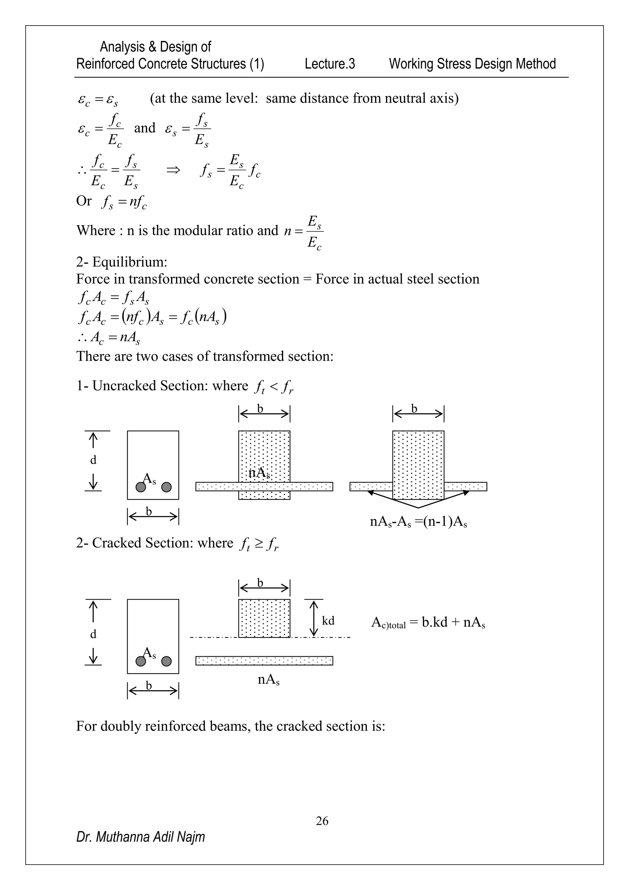


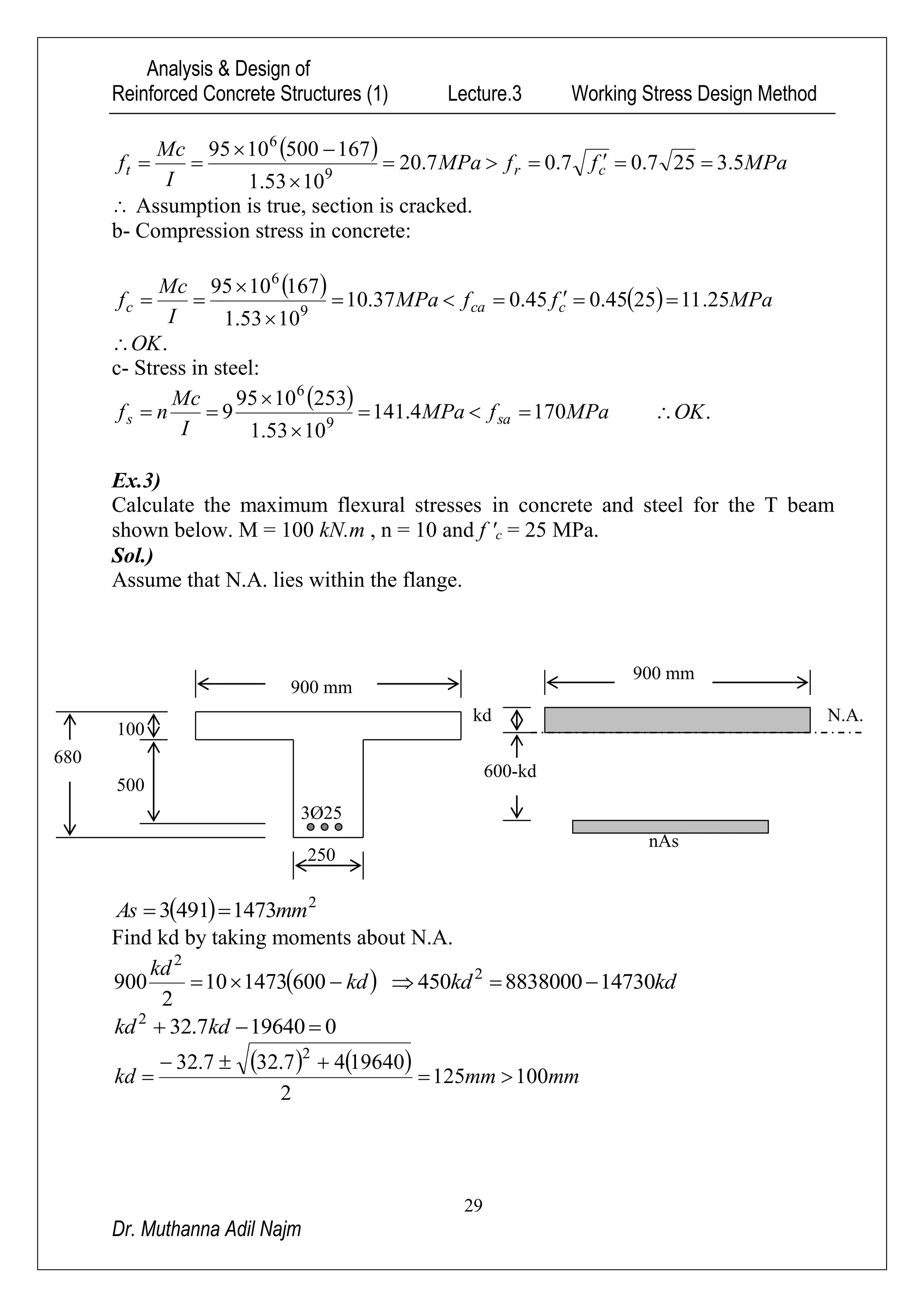


The document summarizes the working stress design method for reinforced concrete structures. It describes the key assumptions of the method, including that concrete and steel obey Hooke's law, strain is proportional to distance from the neutral axis, and tension in concrete is negligible. The transformed section method is also summarized, where the steel area is replaced by an equivalent concrete area while satisfying compatibility of strains and equilibrium of forces. Several examples are provided to demonstrate calculating stresses in concrete and steel for different beam cross-sections under given loads using the working stress design method.