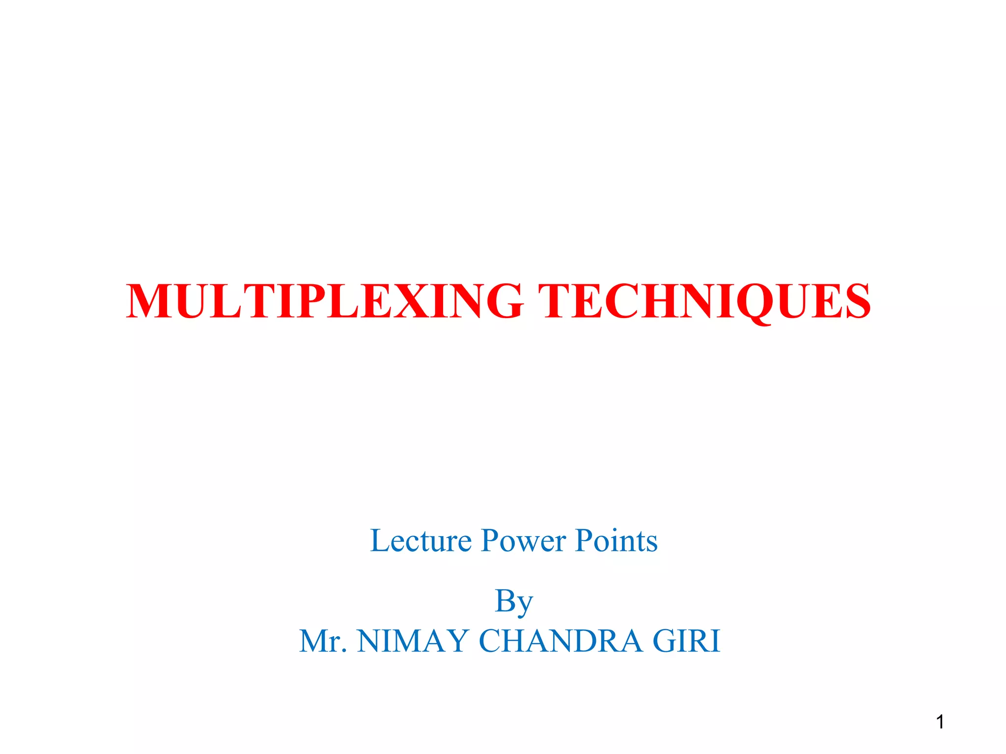
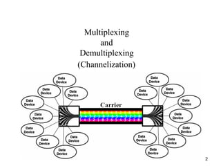
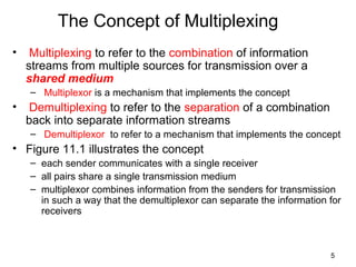
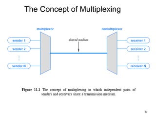
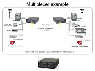
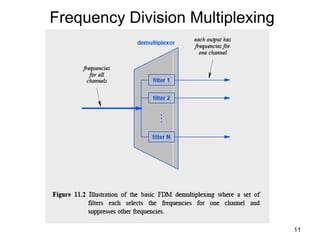
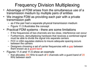
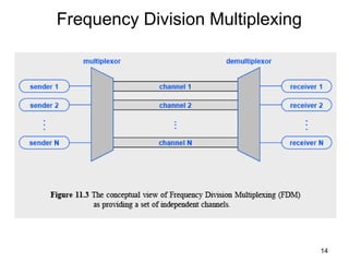
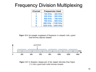
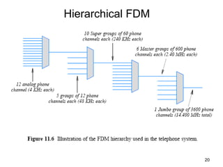
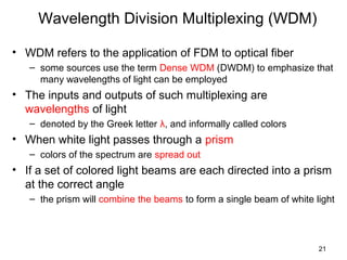
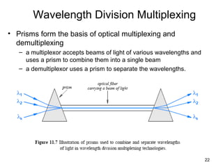
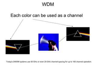
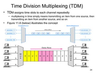
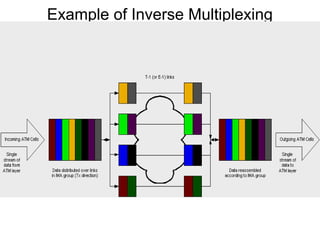
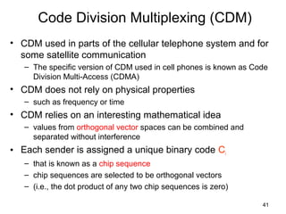
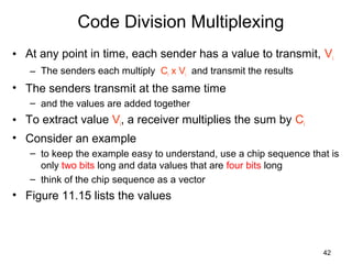
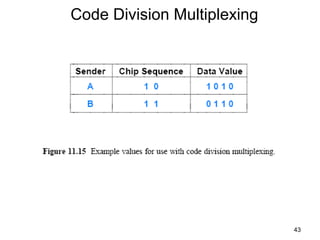
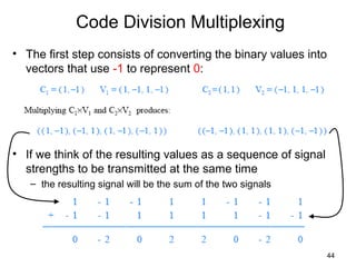
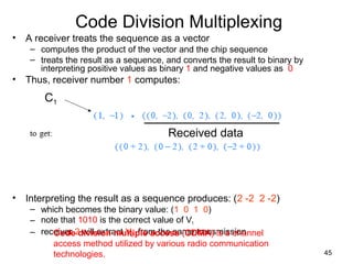
SlideShare a Scribd company logo
1 of 45
1
MULTIPLEXING TECHNIQUES
Lecture Power Points
By
Mr. NIMAY CHANDRA GIRI
2
Multiplexing
and
Demultiplexing
(Channelization)
3
Topics Covered
• Introduction
• The Concept of Multiplexing
• The Basic Types of Multiplexing
• Frequency Division Multiplexing (FDM)
• Using a Range of Frequencies Per Channel
• Hierarchical FDM
• Wavelength Division Multiplexing (WDM)
• Time Division Multiplexing (TDM)
• Synchronous TDM
• Framing Used in the Telephone System Version of TDM
• Hierarchical TDM
• The Problem with Synchronous TDM: Unfilled Slots
• Statistical TDM
• Inverse Multiplexing
• Code Division Multiplexing
4
Introduction
• This chapter
– continues the discussion of data communications by introducing
multiplexing
– describes the motivation
– defines basic types of multiplexing that are used throughout
computer networks and the Internet
– explains how modulated carriers provide the basis for many
multiplexing mechanisms
5
The Concept of Multiplexing
• Multiplexing to refer to the combination of information
streams from multiple sources for transmission over a
shared medium
– Multiplexor is a mechanism that implements the concept
• Demultiplexing to refer to the separation of a combination
back into separate information streams
– Demultiplexor to refer to a mechanism that implements the concept
• Figure 11.1 illustrates the concept
– each sender communicates with a single receiver
– all pairs share a single transmission medium
– multiplexor combines information from the senders for transmission
in such a way that the demultiplexor can separate the information for
receivers
6
The Concept of Multiplexing
Multiplexing in networksMainpurposeis?
Sharingthemedium
Multiplexer example
9
The Basic Types of Multiplexing
• There are four basic approaches to multiplexing that each
have a set of variations and implementations
– Frequency Division Multiplexing (FDM)
– Wavelength Division Multiplexing (WDM)
– Time Division Multiplexing (TDM)
– Code Division Multiplexing (CDM)
• TDM and FDM are widely used
• WDM is a form of FDM used for optical fiber
• CDM is a mathematical approach used in cell phone
mechanisms
10
Frequency Division Multiplexing
• A set of radio stations/TV can transmit electromagnetic
signals simultaneously
– With little interference, they each use a separate channel (i.e.,
carrier frequency)
• It is possible to send simultaneously multiple carrier waves
over a single copper wire, e.g. 24 digitized voice on a
copper wire= T1-carrier system
• A demultiplexer applies a set of filters that each extract a
small range of frequencies near one of the carrier
frequencies
• Figure 11.2 illustrates the organization
– A key idea is that the filters used in FDM only examine frequencies
• FDM mechanism will separate the frequency from others
without otherwise modifying the signal
11
Frequency Division Multiplexing
Example usage of Multiplexing in DSSS (used in
cell phone technology)
13
Frequency Division Multiplexing
• Advantage of FDM arises from the simultaneous use of a
transmission medium by multiple pairs of entities
• We imagine FDM as providing each pair with a private
transmission path
– as if the pair had a separate physical transmission medium
– Figure 11.3 illustrates the concept
• Practical FDM systems - there are some limitations
– If the frequencies of two channels are too close, interference can occur
– Furthermore, demultiplexing hardware that receives a combined signal
must be able to divide the signal into separate carriers
– FCC in USA regulates stations to insure adequate spacing occurs
between the carriers
– Designers choosing a set of carrier frequencies with a gap between
them known as a guard band
• Figures 11.4 and 11.5 show an example
– that allocates 200 KHz to each of 6 channels with a guard band of 20
KHz between each
14
Frequency Division Multiplexing
15
Frequency Division Multiplexing
16
Using a Range of Frequencies Per
Channel
• Why does the example allocate blocks of frequencies?
• Consider the following characteristics of FDM:
– Long-lived: FDM, the idea of dividing the electromagnetic spectrum
into channels, arose in early experiments in radio
– Widely used: FDM is used in broadcast radio and television, cable
television, and the AMPS cellular telephone
– Analog: FDM multiplexing and demultiplexing hardware accepts and
delivers analog signals
• Even if a carrier has been modulated to contain digital information, FDM
hardware treats the carrier as an analog wave
– Versatile: Because it filters on ranges of frequency without
examining other aspects of signals, FDM is versatile
17
Using a Range of Frequencies Per
Channel
• The analog characteristic has the disadvantage of making
FDM susceptible to noise and distortion
• Most FDM systems assign each sender and receiver pair a
range of frequencies
• FDM has the ability to choose how the frequencies can be
used
• There are two primary ways that systems use a range of
frequencies
– Increase the data rate
– Increase immunity to interference
• To increase the overall data rate
– a sender divides the frequency range of the channel into K carriers
– and sends 1/K of the data over each carrier
18
Using a Range of Frequencies Per
Channel
• A sender can perform FDM within an allocated channel
– Sometimes, the term subchannel allocation refers to the subdivision
• To increase immunity to interference
– a sender uses a technique known as spread spectrum
• Various forms are suggested, but basic idea is
– divide the range of the channel into K carriers
– transmit the data spread(using secret pattern) over multiple channels
– allow a receiver to use a copy compose the data that arrives using
the same spread pattern used by the sender
• The scheme works well in cases where noise is likely to
interfere with some frequencies at a given time
The Godmother of Spread Spectrum - Hedy Lamarr
19
Hierarchical FDM
• Flexibility in FDM arises from the ability of hardware to shift
frequencies
• If a set of incoming signals all use the frequency range
between 0 and 4 KHz
– multiplexing hardware can leave the first stage as is
– map the second onto the range 4 KHz to 8 KHz
– map the third onto the range 8 KHz to 12 KHz, and so on
• Hierarchy in FDM multiplexors is that each maps its inputs
to a larger, continuous band of frequencies
• Figure 11.6 illustrates the concept of hierarchical FDM
20
Hierarchical FDM
21
Wavelength Division Multiplexing (WDM)
• WDM refers to the application of FDM to optical fiber
– some sources use the term Dense WDM (DWDM) to emphasize that
many wavelengths of light can be employed
• The inputs and outputs of such multiplexing are
wavelengths of light
– denoted by the Greek letter λ, and informally called colors
• When white light passes through a prism
– colors of the spectrum are spread out
• If a set of colored light beams are each directed into a prism
at the correct angle
– the prism will combine the beams to form a single beam of white light
22
Wavelength Division Multiplexing
• Prisms form the basis of optical multiplexing and
demultiplexing
– a multiplexor accepts beams of light of various wavelengths and
uses a prism to combine them into a single beam
– a demultiplexor uses a prism to separate the wavelengths.
WDM
Each color can be used as a channel
Today's DWDM systems use 50 GHz or even 25 GHz channel spacing for up to 160 channel operation.
24
Time Division Multiplexing (TDM)
• TDM assigns time slots to each channel repeatedly
– multiplexing in time simply means transmitting an item from one source, then
transmitting an item from another source, and so on
• Figure 11.8 (below) illustrates the concept
25
Synchronous TDM
• TDM is a broad concept that appears in many forms
– It is widely used throughout the Internet
• Figure 11.8 is a conceptual view, and the details may vary
• Figure shows items being sent in a round-robin fashion
– Most TDMs work this way
– Figure shows a slight gap between items
– Recall from Chapter 9 that no gap occurs between bits if a
communication system uses synchronous transmission
– When TDM is applied to synchronous networks, no gap occurs
between items; the result is known as Synchronous TDM
• Figure 11.9 illustrates how synchronous TDM works for a
system of four senders
Synchronous TDM
26
27
Framing Used in the Telephone System
Version of TDM
• Telephone systems use synchronous TDM to multiplex
digital streams from multiple phone calls
– they use the acronym TDM to refer to the specific form of TDM used
to multiplex digital telephone calls
• The phone system TDM includes an interesting technique
– to insure that a demultiplexer stays synchronized with the multiplexer
• Why is synchronization needed?
– observe that a synchronous TDM sends one slot after another
without any indication of the output to which a given slot occurs
– A demultiplexer cannot tell where a slot begins– a slight difference in
the clocks used to time bits can cause a demultiplexer to
misinterpret the bit stream
28
Framing Used in the Telephone System
Version of TDM
• To prevent misinterpretation, the version of TDM used in the
phone system includes an extra framing channel as input
• Instead of taking a complete slot, framing inserts a single bit
in the stream on each round
• A demultiplexor extracts data from the framing channel and
checks for alternating 0 and 1 bits
• If an error causes a demultiplexor to lose a bit
– it is highly likely that the framing check will detect the error and allow
the transmission to be restarted
• Figure 11.10 illustrates the use of framing bits
Framing Used in the Telephone System
Version of TDM
29
30
Hierarchical TDM
• Like FDM, TDM can be arranged in a hierarchy
• The difference is that each successive stage of a TDM
hierarchy uses N times the bit rate
– In FDM, each successive stage uses N times the frequencies
• Additional framing bits are added to the data
– means that the bit rate of each successive layer of hierarchy is
slightly greater than the aggregate voice traffic
• Compare the example TDM hierarchy
– in Figure 11.11 with the FDM example in Figure 11.6
Hierarchical TDM
31
32
The Problem with Synchronous TDM:
Unfilled Slots
• Synchronous TDM works well if each source produces data
at a uniform, fixed rate equal to 1/N of the capacity of the
shared medium
• Many sources generate data in bursts, with idle time
between bursts
• To understand why, consider the example in Figure 11.12
– sources on the left produce data items at random
– the synchronous multiplexor leaves a slot unfilled
• if the corresponding source has not produced an item by the time the slot
must be sent
• In practice, a slot cannot be empty because the underlying
system must continue to transmit data
– the slot is assigned a value (such as zero)
– and an extra bit is set to indicate that the value is invalid
The Problem with Synchronous TDM:
Unfilled Slots
33
34
Statistical TDM
• How can a multiplexing system make better use of a shared
medium?
• One technique to increase the overall data rate is known as
statistical TDM or statistical multiplexing
– some literature uses the term asynchronous TDM
• The technique is straightforward:
– select items for transmission in a round-robin fashion
– but instead of leaving a slot unfilled, skip any source that does not
have data ready
• By eliminating unused slots
– statistical TDM takes less time to send the same amount of data
• Figure 11.13 illustrates how a statistical TDM system sends
the data from Figure 11.12 in only 8 slots instead of 12
Statistical TDM
35
36
Statistical TDM
• Statistical multiplexing incurs extra overhead shown below:
– Consider demultiplexing:
• In a synchronous TDM system a demultiplexor knows that every N slot
corresponds to a given receiver
• In a statistical multiplexing system, the data in a given slot can correspond to
any receiver
– Each slot must contain the identification of the receiver to which the
data is being sent
• Later chapters discuss identification mechanisms
– that are used with statistical multiplexing in packet switching
networks and the Internet
37
Inverse Multiplexing
• Assume a case where a connection between two points
consists of multiple transmission media
– but no single medium has a bit rate that is sufficient
• At the core of the Internet, for example, service providers
need higher bit rates than are available
• To solve the problem, multiplexing is used in reverse
– spread a high-speed digital input over multiple lower-speed circuits
for transmission and combine the results at the receiving end
• Figure 11.14 illustrates the concept
Inverse Multiplexing
38
39
Inverse Multiplexing
• An inverse multiplexor cannot be constructed by connecting
the pieces of a conventional multiplexor backward
– hardware must be designed so that the sender and receiver agree
on how data arriving from the input will be distributed over the lower-
speed connections
– to insure that all data is delivered in the same order as it arrived, the
system must be engineered to handle cases
• where one or more of the lower-speed connections has longer latency than
others
• Despite its complexity, inverse multiplexing is widely used in
the Internet
Example of Inverse Multiplexing
41
Code Division Multiplexing (CDM)
• CDM used in parts of the cellular telephone system and for
some satellite communication
– The specific version of CDM used in cell phones is known as Code
Division Multi-Access (CDMA)
• CDM does not rely on physical properties
– such as frequency or time
• CDM relies on an interesting mathematical idea
– values from orthogonal vector spaces can be combined and
separated without interference
• Each sender is assigned a unique binary code Ci
– that is known as a chip sequence
– chip sequences are selected to be orthogonal vectors
– (i.e., the dot product of any two chip sequences is zero)
42
Code Division Multiplexing
• At any point in time, each sender has a value to transmit, Vi
– The senders each multiply Ci x Vi and transmit the results
• The senders transmit at the same time
– and the values are added together
• To extract value Vi, a receiver multiplies the sum by Ci
• Consider an example
– to keep the example easy to understand, use a chip sequence that is
only two bits long and data values that are four bits long
– think of the chip sequence as a vector
• Figure 11.15 lists the values
Code Division Multiplexing
43
44
Code Division Multiplexing
• The first step consists of converting the binary values into
vectors that use -1 to represent 0:
• If we think of the resulting values as a sequence of signal
strengths to be transmitted at the same time
– the resulting signal will be the sum of the two signals
45
Code Division Multiplexing
• A receiver treats the sequence as a vector
– computes the product of the vector and the chip sequence
– treats the result as a sequence, and converts the result to binary by
interpreting positive values as binary 1 and negative values as 0
• Thus, receiver number 1 computes:
• Interpreting the result as a sequence produces: (2 -2 2 -2)
– which becomes the binary value: (1 0 1 0)
– note that 1010 is the correct value of V1
– receiver 2 will extract V2 from the same transmission
C1
Received data
Code division multiple access (CDMA) is a channel
access method utilized by various radio communication
technologies.

More Related Content

What's hot (20)

OFDM for LTE
OFDM for LTEOFDM for LTE
OFDM for LTE
 
Multiplexing
MultiplexingMultiplexing
Multiplexing
 
Mobile Radio Propagations
Mobile Radio PropagationsMobile Radio Propagations
Mobile Radio Propagations
 
Multiple acces techniques
Multiple acces techniquesMultiple acces techniques
Multiple acces techniques
 
MIMO.ppt (2) 2
MIMO.ppt (2) 2MIMO.ppt (2) 2
MIMO.ppt (2) 2
 
TDMA, FDMA, and CDMA
TDMA, FDMA, and CDMATDMA, FDMA, and CDMA
TDMA, FDMA, and CDMA
 
FDMA-TDMA-CDMA
FDMA-TDMA-CDMAFDMA-TDMA-CDMA
FDMA-TDMA-CDMA
 
Multiplexing, Frequency Division Multiplexing (FDM), Time Division Multiplexi...
Multiplexing, Frequency Division Multiplexing (FDM), Time Division Multiplexi...Multiplexing, Frequency Division Multiplexing (FDM), Time Division Multiplexi...
Multiplexing, Frequency Division Multiplexing (FDM), Time Division Multiplexi...
 
Frequency Division Multiple Access (FDMA)
Frequency Division Multiple Access (FDMA)Frequency Division Multiple Access (FDMA)
Frequency Division Multiple Access (FDMA)
 
Spread spectrum modulation
Spread spectrum modulationSpread spectrum modulation
Spread spectrum modulation
 
MIMO
MIMOMIMO
MIMO
 
Chapter 7 multiple access techniques
Chapter 7 multiple access techniquesChapter 7 multiple access techniques
Chapter 7 multiple access techniques
 
FDMA & TDMA
FDMA & TDMAFDMA & TDMA
FDMA & TDMA
 
Propagation Model
Propagation ModelPropagation Model
Propagation Model
 
Ofdma Basics
Ofdma BasicsOfdma Basics
Ofdma Basics
 
IS-95 Cdma
IS-95 CdmaIS-95 Cdma
IS-95 Cdma
 
Ofdm
OfdmOfdm
Ofdm
 
Introduction To Wireless Fading Channels
Introduction To Wireless Fading ChannelsIntroduction To Wireless Fading Channels
Introduction To Wireless Fading Channels
 
Small scale fading
Small scale fadingSmall scale fading
Small scale fading
 
Link budget calculation
Link budget calculationLink budget calculation
Link budget calculation
 

Viewers also liked

Multiplexing and switching(TDM ,FDM, Data gram, circuit switching)
Multiplexing and switching(TDM ,FDM, Data gram, circuit switching)Multiplexing and switching(TDM ,FDM, Data gram, circuit switching)
Multiplexing and switching(TDM ,FDM, Data gram, circuit switching)Adil Mehmoood
 
Transmission impairments
Transmission impairmentsTransmission impairments
Transmission impairmentsOnline
 
Transmission impairments
Transmission impairmentsTransmission impairments
Transmission impairmentsavocado1111
 
Multiplexing
MultiplexingMultiplexing
Multiplexingstooty s
 
Networks classification
Networks classificationNetworks classification
Networks classificationMukesh Chinta
 
Chapter 3 - Data and Signals
Chapter 3 - Data and SignalsChapter 3 - Data and Signals
Chapter 3 - Data and SignalsWayne Jones Jnr
 

Viewers also liked (13)

7 multiplexing
7 multiplexing7 multiplexing
7 multiplexing
 
Wdm
WdmWdm
Wdm
 
Multiplexing and switching(TDM ,FDM, Data gram, circuit switching)
Multiplexing and switching(TDM ,FDM, Data gram, circuit switching)Multiplexing and switching(TDM ,FDM, Data gram, circuit switching)
Multiplexing and switching(TDM ,FDM, Data gram, circuit switching)
 
Ch 03
Ch 03Ch 03
Ch 03
 
osi vs tcp/ip
osi vs tcp/iposi vs tcp/ip
osi vs tcp/ip
 
Transmission impairments
Transmission impairmentsTransmission impairments
Transmission impairments
 
Transmission impairments
Transmission impairmentsTransmission impairments
Transmission impairments
 
Multiplexing
MultiplexingMultiplexing
Multiplexing
 
Wavelength division multiplexing
Wavelength division multiplexingWavelength division multiplexing
Wavelength division multiplexing
 
Multiplexing
MultiplexingMultiplexing
Multiplexing
 
Networks classification
Networks classificationNetworks classification
Networks classification
 
3.1.2 classification of network
3.1.2 classification of network3.1.2 classification of network
3.1.2 classification of network
 
Chapter 3 - Data and Signals
Chapter 3 - Data and SignalsChapter 3 - Data and Signals
Chapter 3 - Data and Signals
 

Similar to Multiplexing, fdma,tdma,cdma

Multiplexing and spreading
Multiplexing and spreadingMultiplexing and spreading
Multiplexing and spreadingShankar Gangaju
 
FDM AND TDM (multiplexing)-Communication system ppt
FDM AND TDM (multiplexing)-Communication system pptFDM AND TDM (multiplexing)-Communication system ppt
FDM AND TDM (multiplexing)-Communication system pptMohitDangi8
 
Digital Communication 4
Digital Communication 4Digital Communication 4
Digital Communication 4admercano101
 
Multiplexing tdma fdma cdma wdma
Multiplexing tdma fdma cdma wdmaMultiplexing tdma fdma cdma wdma
Multiplexing tdma fdma cdma wdmaShadab Siddiqui
 
Multiplexing.pptx
Multiplexing.pptxMultiplexing.pptx
Multiplexing.pptxVenkyKadari
 
DATA COMMUNICTION AND NETWROKING.pptx
DATA COMMUNICTION AND NETWROKING.pptxDATA COMMUNICTION AND NETWROKING.pptx
DATA COMMUNICTION AND NETWROKING.pptxAnishkumar343890
 
unit 1 section 7.pptx
unit 1 section 7.pptxunit 1 section 7.pptx
unit 1 section 7.pptxmani651780
 
Bandwidth Utilization Multiplexing and Spectrum Spreading
Bandwidth Utilization Multiplexing and Spectrum SpreadingBandwidth Utilization Multiplexing and Spectrum Spreading
Bandwidth Utilization Multiplexing and Spectrum SpreadingMeenakshi Paul
 
Physical layer concepts
Physical layer conceptsPhysical layer concepts
Physical layer conceptsSahil Rana
 
scribd.vpdfs.com_multiple-access-fdma-cdma-tdma-sdma-dsss-fhss-aloha-packet-r...
scribd.vpdfs.com_multiple-access-fdma-cdma-tdma-sdma-dsss-fhss-aloha-packet-r...scribd.vpdfs.com_multiple-access-fdma-cdma-tdma-sdma-dsss-fhss-aloha-packet-r...
scribd.vpdfs.com_multiple-access-fdma-cdma-tdma-sdma-dsss-fhss-aloha-packet-r...NadaAAmin
 
Multiplexing & types
Multiplexing & typesMultiplexing & types
Multiplexing & typesarslan895
 

Similar to Multiplexing, fdma,tdma,cdma (20)

Multiplexing and spreading
Multiplexing and spreadingMultiplexing and spreading
Multiplexing and spreading
 
1.pptx
1.pptx1.pptx
1.pptx
 
FDM AND TDM (multiplexing)-Communication system ppt
FDM AND TDM (multiplexing)-Communication system pptFDM AND TDM (multiplexing)-Communication system ppt
FDM AND TDM (multiplexing)-Communication system ppt
 
MULTIPLEXERS
MULTIPLEXERSMULTIPLEXERS
MULTIPLEXERS
 
Digital Communication 4
Digital Communication 4Digital Communication 4
Digital Communication 4
 
Multiplexing tdma fdma cdma wdma
Multiplexing tdma fdma cdma wdmaMultiplexing tdma fdma cdma wdma
Multiplexing tdma fdma cdma wdma
 
Multiplexing
MultiplexingMultiplexing
Multiplexing
 
Multiplexing.pptx
Multiplexing.pptxMultiplexing.pptx
Multiplexing.pptx
 
3 multiplexing-wdm
3 multiplexing-wdm3 multiplexing-wdm
3 multiplexing-wdm
 
DATA COMMUNICTION AND NETWROKING.pptx
DATA COMMUNICTION AND NETWROKING.pptxDATA COMMUNICTION AND NETWROKING.pptx
DATA COMMUNICTION AND NETWROKING.pptx
 
unit 1 section 7.pptx
unit 1 section 7.pptxunit 1 section 7.pptx
unit 1 section 7.pptx
 
Bandwidth Utilization Multiplexing and Spectrum Spreading
Bandwidth Utilization Multiplexing and Spectrum SpreadingBandwidth Utilization Multiplexing and Spectrum Spreading
Bandwidth Utilization Multiplexing and Spectrum Spreading
 
Multiplexing
MultiplexingMultiplexing
Multiplexing
 
v unit (1).pptx
v unit (1).pptxv unit (1).pptx
v unit (1).pptx
 
MULTIPLEXING.pptx
MULTIPLEXING.pptxMULTIPLEXING.pptx
MULTIPLEXING.pptx
 
Physical layer concepts
Physical layer conceptsPhysical layer concepts
Physical layer concepts
 
Bandwidth utilization
Bandwidth utilizationBandwidth utilization
Bandwidth utilization
 
Multiplexing : FDM
Multiplexing : FDMMultiplexing : FDM
Multiplexing : FDM
 
scribd.vpdfs.com_multiple-access-fdma-cdma-tdma-sdma-dsss-fhss-aloha-packet-r...
scribd.vpdfs.com_multiple-access-fdma-cdma-tdma-sdma-dsss-fhss-aloha-packet-r...scribd.vpdfs.com_multiple-access-fdma-cdma-tdma-sdma-dsss-fhss-aloha-packet-r...
scribd.vpdfs.com_multiple-access-fdma-cdma-tdma-sdma-dsss-fhss-aloha-packet-r...
 
Multiplexing & types
Multiplexing & typesMultiplexing & types
Multiplexing & types
 

More from nimay1

Logic gate implementing without using ICs by Nimay Giri
Logic gate implementing without using ICs by Nimay GiriLogic gate implementing without using ICs by Nimay Giri
Logic gate implementing without using ICs by Nimay Girinimay1
 
Numbering plan system
Numbering plan systemNumbering plan system
Numbering plan systemnimay1
 
Mobile tower site, Nimay Giri
Mobile tower site, Nimay GiriMobile tower site, Nimay Giri
Mobile tower site, Nimay Girinimay1
 
Win ppt
Win pptWin ppt
Win pptnimay1
 
Multiplexing
MultiplexingMultiplexing
Multiplexingnimay1
 
Cell tower, BTS & antennas
Cell tower, BTS & antennasCell tower, BTS & antennas
Cell tower, BTS & antennasnimay1
 
MIMO-OFDM for 4G network
MIMO-OFDM for 4G networkMIMO-OFDM for 4G network
MIMO-OFDM for 4G networknimay1
 

More from nimay1 (7)

Logic gate implementing without using ICs by Nimay Giri
Logic gate implementing without using ICs by Nimay GiriLogic gate implementing without using ICs by Nimay Giri
Logic gate implementing without using ICs by Nimay Giri
 
Numbering plan system
Numbering plan systemNumbering plan system
Numbering plan system
 
Mobile tower site, Nimay Giri
Mobile tower site, Nimay GiriMobile tower site, Nimay Giri
Mobile tower site, Nimay Giri
 
Win ppt
Win pptWin ppt
Win ppt
 
Multiplexing
MultiplexingMultiplexing
Multiplexing
 
Cell tower, BTS & antennas
Cell tower, BTS & antennasCell tower, BTS & antennas
Cell tower, BTS & antennas
 
MIMO-OFDM for 4G network
MIMO-OFDM for 4G networkMIMO-OFDM for 4G network
MIMO-OFDM for 4G network
 

Recently uploaded

CCS355 Neural Network & Deep Learning Unit II Notes with Question bank .pdf
CCS355 Neural Network & Deep Learning Unit II Notes with Question bank .pdfCCS355 Neural Network & Deep Learning Unit II Notes with Question bank .pdf
CCS355 Neural Network & Deep Learning Unit II Notes with Question bank .pdfAsst.prof M.Gokilavani
 
Past, Present and Future of Generative AI
Past, Present and Future of Generative AIPast, Present and Future of Generative AI
Past, Present and Future of Generative AIabhishek36461
 
Effects of rheological properties on mixing
Effects of rheological properties on mixingEffects of rheological properties on mixing
Effects of rheological properties on mixingviprabot1
 
Decoding Kotlin - Your guide to solving the mysterious in Kotlin.pptx
Decoding Kotlin - Your guide to solving the mysterious in Kotlin.pptxDecoding Kotlin - Your guide to solving the mysterious in Kotlin.pptx
Decoding Kotlin - Your guide to solving the mysterious in Kotlin.pptxJoão Esperancinha
 
Artificial-Intelligence-in-Electronics (K).pptx
Artificial-Intelligence-in-Electronics (K).pptxArtificial-Intelligence-in-Electronics (K).pptx
Artificial-Intelligence-in-Electronics (K).pptxbritheesh05
 
An experimental study in using natural admixture as an alternative for chemic...
An experimental study in using natural admixture as an alternative for chemic...An experimental study in using natural admixture as an alternative for chemic...
An experimental study in using natural admixture as an alternative for chemic...Chandu841456
 
complete construction, environmental and economics information of biomass com...
complete construction, environmental and economics information of biomass com...complete construction, environmental and economics information of biomass com...
complete construction, environmental and economics information of biomass com...asadnawaz62
 
Introduction to Machine Learning Unit-3 for II MECH
Introduction to Machine Learning Unit-3 for II MECHIntroduction to Machine Learning Unit-3 for II MECH
Introduction to Machine Learning Unit-3 for II MECHC Sai Kiran
 
Application of Residue Theorem to evaluate real integrations.pptx
Application of Residue Theorem to evaluate real integrations.pptxApplication of Residue Theorem to evaluate real integrations.pptx
Application of Residue Theorem to evaluate real integrations.pptx959SahilShah
 
Call Girls Narol 7397865700 Independent Call Girls
Call Girls Narol 7397865700 Independent Call GirlsCall Girls Narol 7397865700 Independent Call Girls
Call Girls Narol 7397865700 Independent Call Girlsssuser7cb4ff
 
Architect Hassan Khalil Portfolio for 2024
Architect Hassan Khalil Portfolio for 2024Architect Hassan Khalil Portfolio for 2024
Architect Hassan Khalil Portfolio for 2024hassan khalil
 
Introduction-To-Agricultural-Surveillance-Rover.pptx
Introduction-To-Agricultural-Surveillance-Rover.pptxIntroduction-To-Agricultural-Surveillance-Rover.pptx
Introduction-To-Agricultural-Surveillance-Rover.pptxk795866
 
Heart Disease Prediction using machine learning.pptx
Heart Disease Prediction using machine learning.pptxHeart Disease Prediction using machine learning.pptx
Heart Disease Prediction using machine learning.pptxPoojaBan
 
DATA ANALYTICS PPT definition usage example
DATA ANALYTICS PPT definition usage exampleDATA ANALYTICS PPT definition usage example
DATA ANALYTICS PPT definition usage examplePragyanshuParadkar1
 
CCS355 Neural Network & Deep Learning UNIT III notes and Question bank .pdf
CCS355 Neural Network & Deep Learning UNIT III notes and Question bank .pdfCCS355 Neural Network & Deep Learning UNIT III notes and Question bank .pdf
CCS355 Neural Network & Deep Learning UNIT III notes and Question bank .pdfAsst.prof M.Gokilavani
 
Gurgaon ✡️9711147426✨Call In girls Gurgaon Sector 51 escort service
Gurgaon ✡️9711147426✨Call In girls Gurgaon Sector 51 escort serviceGurgaon ✡️9711147426✨Call In girls Gurgaon Sector 51 escort service
Gurgaon ✡️9711147426✨Call In girls Gurgaon Sector 51 escort servicejennyeacort
 
Biology for Computer Engineers Course Handout.pptx
Biology for Computer Engineers Course Handout.pptxBiology for Computer Engineers Course Handout.pptx
Biology for Computer Engineers Course Handout.pptxDeepakSakkari2
 

Recently uploaded (20)

CCS355 Neural Network & Deep Learning Unit II Notes with Question bank .pdf
CCS355 Neural Network & Deep Learning Unit II Notes with Question bank .pdfCCS355 Neural Network & Deep Learning Unit II Notes with Question bank .pdf
CCS355 Neural Network & Deep Learning Unit II Notes with Question bank .pdf
 
Past, Present and Future of Generative AI
Past, Present and Future of Generative AIPast, Present and Future of Generative AI
Past, Present and Future of Generative AI
 
Effects of rheological properties on mixing
Effects of rheological properties on mixingEffects of rheological properties on mixing
Effects of rheological properties on mixing
 
Decoding Kotlin - Your guide to solving the mysterious in Kotlin.pptx
Decoding Kotlin - Your guide to solving the mysterious in Kotlin.pptxDecoding Kotlin - Your guide to solving the mysterious in Kotlin.pptx
Decoding Kotlin - Your guide to solving the mysterious in Kotlin.pptx
 
Artificial-Intelligence-in-Electronics (K).pptx
Artificial-Intelligence-in-Electronics (K).pptxArtificial-Intelligence-in-Electronics (K).pptx
Artificial-Intelligence-in-Electronics (K).pptx
 
9953056974 Call Girls In South Ex, Escorts (Delhi) NCR.pdf
9953056974 Call Girls In South Ex, Escorts (Delhi) NCR.pdf9953056974 Call Girls In South Ex, Escorts (Delhi) NCR.pdf
9953056974 Call Girls In South Ex, Escorts (Delhi) NCR.pdf
 
An experimental study in using natural admixture as an alternative for chemic...
An experimental study in using natural admixture as an alternative for chemic...An experimental study in using natural admixture as an alternative for chemic...
An experimental study in using natural admixture as an alternative for chemic...
 
complete construction, environmental and economics information of biomass com...
complete construction, environmental and economics information of biomass com...complete construction, environmental and economics information of biomass com...
complete construction, environmental and economics information of biomass com...
 
Introduction to Machine Learning Unit-3 for II MECH
Introduction to Machine Learning Unit-3 for II MECHIntroduction to Machine Learning Unit-3 for II MECH
Introduction to Machine Learning Unit-3 for II MECH
 
Application of Residue Theorem to evaluate real integrations.pptx
Application of Residue Theorem to evaluate real integrations.pptxApplication of Residue Theorem to evaluate real integrations.pptx
Application of Residue Theorem to evaluate real integrations.pptx
 
Call Girls Narol 7397865700 Independent Call Girls
Call Girls Narol 7397865700 Independent Call GirlsCall Girls Narol 7397865700 Independent Call Girls
Call Girls Narol 7397865700 Independent Call Girls
 
Architect Hassan Khalil Portfolio for 2024
Architect Hassan Khalil Portfolio for 2024Architect Hassan Khalil Portfolio for 2024
Architect Hassan Khalil Portfolio for 2024
 
Introduction-To-Agricultural-Surveillance-Rover.pptx
Introduction-To-Agricultural-Surveillance-Rover.pptxIntroduction-To-Agricultural-Surveillance-Rover.pptx
Introduction-To-Agricultural-Surveillance-Rover.pptx
 
Heart Disease Prediction using machine learning.pptx
Heart Disease Prediction using machine learning.pptxHeart Disease Prediction using machine learning.pptx
Heart Disease Prediction using machine learning.pptx
 
DATA ANALYTICS PPT definition usage example
DATA ANALYTICS PPT definition usage exampleDATA ANALYTICS PPT definition usage example
DATA ANALYTICS PPT definition usage example
 
CCS355 Neural Network & Deep Learning UNIT III notes and Question bank .pdf
CCS355 Neural Network & Deep Learning UNIT III notes and Question bank .pdfCCS355 Neural Network & Deep Learning UNIT III notes and Question bank .pdf
CCS355 Neural Network & Deep Learning UNIT III notes and Question bank .pdf
 
Exploring_Network_Security_with_JA3_by_Rakesh Seal.pptx
Exploring_Network_Security_with_JA3_by_Rakesh Seal.pptxExploring_Network_Security_with_JA3_by_Rakesh Seal.pptx
Exploring_Network_Security_with_JA3_by_Rakesh Seal.pptx
 
Gurgaon ✡️9711147426✨Call In girls Gurgaon Sector 51 escort service
Gurgaon ✡️9711147426✨Call In girls Gurgaon Sector 51 escort serviceGurgaon ✡️9711147426✨Call In girls Gurgaon Sector 51 escort service
Gurgaon ✡️9711147426✨Call In girls Gurgaon Sector 51 escort service
 
Biology for Computer Engineers Course Handout.pptx
Biology for Computer Engineers Course Handout.pptxBiology for Computer Engineers Course Handout.pptx
Biology for Computer Engineers Course Handout.pptx
 
🔝9953056974🔝!!-YOUNG call girls in Rajendra Nagar Escort rvice Shot 2000 nigh...
🔝9953056974🔝!!-YOUNG call girls in Rajendra Nagar Escort rvice Shot 2000 nigh...🔝9953056974🔝!!-YOUNG call girls in Rajendra Nagar Escort rvice Shot 2000 nigh...
🔝9953056974🔝!!-YOUNG call girls in Rajendra Nagar Escort rvice Shot 2000 nigh...
 

Multiplexing, fdma,tdma,cdma

  • 1. 1 MULTIPLEXING TECHNIQUES Lecture Power Points By Mr. NIMAY CHANDRA GIRI
  • 3. 3 Topics Covered • Introduction • The Concept of Multiplexing • The Basic Types of Multiplexing • Frequency Division Multiplexing (FDM) • Using a Range of Frequencies Per Channel • Hierarchical FDM • Wavelength Division Multiplexing (WDM) • Time Division Multiplexing (TDM) • Synchronous TDM • Framing Used in the Telephone System Version of TDM • Hierarchical TDM • The Problem with Synchronous TDM: Unfilled Slots • Statistical TDM • Inverse Multiplexing • Code Division Multiplexing
  • 4. 4 Introduction • This chapter – continues the discussion of data communications by introducing multiplexing – describes the motivation – defines basic types of multiplexing that are used throughout computer networks and the Internet – explains how modulated carriers provide the basis for many multiplexing mechanisms
  • 5. 5 The Concept of Multiplexing • Multiplexing to refer to the combination of information streams from multiple sources for transmission over a shared medium – Multiplexor is a mechanism that implements the concept • Demultiplexing to refer to the separation of a combination back into separate information streams – Demultiplexor to refer to a mechanism that implements the concept • Figure 11.1 illustrates the concept – each sender communicates with a single receiver – all pairs share a single transmission medium – multiplexor combines information from the senders for transmission in such a way that the demultiplexor can separate the information for receivers
  • 6. 6 The Concept of Multiplexing
  • 9. 9 The Basic Types of Multiplexing • There are four basic approaches to multiplexing that each have a set of variations and implementations – Frequency Division Multiplexing (FDM) – Wavelength Division Multiplexing (WDM) – Time Division Multiplexing (TDM) – Code Division Multiplexing (CDM) • TDM and FDM are widely used • WDM is a form of FDM used for optical fiber • CDM is a mathematical approach used in cell phone mechanisms
  • 10. 10 Frequency Division Multiplexing • A set of radio stations/TV can transmit electromagnetic signals simultaneously – With little interference, they each use a separate channel (i.e., carrier frequency) • It is possible to send simultaneously multiple carrier waves over a single copper wire, e.g. 24 digitized voice on a copper wire= T1-carrier system • A demultiplexer applies a set of filters that each extract a small range of frequencies near one of the carrier frequencies • Figure 11.2 illustrates the organization – A key idea is that the filters used in FDM only examine frequencies • FDM mechanism will separate the frequency from others without otherwise modifying the signal
  • 12. Example usage of Multiplexing in DSSS (used in cell phone technology)
  • 13. 13 Frequency Division Multiplexing • Advantage of FDM arises from the simultaneous use of a transmission medium by multiple pairs of entities • We imagine FDM as providing each pair with a private transmission path – as if the pair had a separate physical transmission medium – Figure 11.3 illustrates the concept • Practical FDM systems - there are some limitations – If the frequencies of two channels are too close, interference can occur – Furthermore, demultiplexing hardware that receives a combined signal must be able to divide the signal into separate carriers – FCC in USA regulates stations to insure adequate spacing occurs between the carriers – Designers choosing a set of carrier frequencies with a gap between them known as a guard band • Figures 11.4 and 11.5 show an example – that allocates 200 KHz to each of 6 channels with a guard band of 20 KHz between each
  • 16. 16 Using a Range of Frequencies Per Channel • Why does the example allocate blocks of frequencies? • Consider the following characteristics of FDM: – Long-lived: FDM, the idea of dividing the electromagnetic spectrum into channels, arose in early experiments in radio – Widely used: FDM is used in broadcast radio and television, cable television, and the AMPS cellular telephone – Analog: FDM multiplexing and demultiplexing hardware accepts and delivers analog signals • Even if a carrier has been modulated to contain digital information, FDM hardware treats the carrier as an analog wave – Versatile: Because it filters on ranges of frequency without examining other aspects of signals, FDM is versatile
  • 17. 17 Using a Range of Frequencies Per Channel • The analog characteristic has the disadvantage of making FDM susceptible to noise and distortion • Most FDM systems assign each sender and receiver pair a range of frequencies • FDM has the ability to choose how the frequencies can be used • There are two primary ways that systems use a range of frequencies – Increase the data rate – Increase immunity to interference • To increase the overall data rate – a sender divides the frequency range of the channel into K carriers – and sends 1/K of the data over each carrier
  • 18. 18 Using a Range of Frequencies Per Channel • A sender can perform FDM within an allocated channel – Sometimes, the term subchannel allocation refers to the subdivision • To increase immunity to interference – a sender uses a technique known as spread spectrum • Various forms are suggested, but basic idea is – divide the range of the channel into K carriers – transmit the data spread(using secret pattern) over multiple channels – allow a receiver to use a copy compose the data that arrives using the same spread pattern used by the sender • The scheme works well in cases where noise is likely to interfere with some frequencies at a given time The Godmother of Spread Spectrum - Hedy Lamarr
  • 19. 19 Hierarchical FDM • Flexibility in FDM arises from the ability of hardware to shift frequencies • If a set of incoming signals all use the frequency range between 0 and 4 KHz – multiplexing hardware can leave the first stage as is – map the second onto the range 4 KHz to 8 KHz – map the third onto the range 8 KHz to 12 KHz, and so on • Hierarchy in FDM multiplexors is that each maps its inputs to a larger, continuous band of frequencies • Figure 11.6 illustrates the concept of hierarchical FDM
  • 21. 21 Wavelength Division Multiplexing (WDM) • WDM refers to the application of FDM to optical fiber – some sources use the term Dense WDM (DWDM) to emphasize that many wavelengths of light can be employed • The inputs and outputs of such multiplexing are wavelengths of light – denoted by the Greek letter λ, and informally called colors • When white light passes through a prism – colors of the spectrum are spread out • If a set of colored light beams are each directed into a prism at the correct angle – the prism will combine the beams to form a single beam of white light
  • 22. 22 Wavelength Division Multiplexing • Prisms form the basis of optical multiplexing and demultiplexing – a multiplexor accepts beams of light of various wavelengths and uses a prism to combine them into a single beam – a demultiplexor uses a prism to separate the wavelengths.
  • 23. WDM Each color can be used as a channel Today's DWDM systems use 50 GHz or even 25 GHz channel spacing for up to 160 channel operation.
  • 24. 24 Time Division Multiplexing (TDM) • TDM assigns time slots to each channel repeatedly – multiplexing in time simply means transmitting an item from one source, then transmitting an item from another source, and so on • Figure 11.8 (below) illustrates the concept
  • 25. 25 Synchronous TDM • TDM is a broad concept that appears in many forms – It is widely used throughout the Internet • Figure 11.8 is a conceptual view, and the details may vary • Figure shows items being sent in a round-robin fashion – Most TDMs work this way – Figure shows a slight gap between items – Recall from Chapter 9 that no gap occurs between bits if a communication system uses synchronous transmission – When TDM is applied to synchronous networks, no gap occurs between items; the result is known as Synchronous TDM • Figure 11.9 illustrates how synchronous TDM works for a system of four senders
  • 27. 27 Framing Used in the Telephone System Version of TDM • Telephone systems use synchronous TDM to multiplex digital streams from multiple phone calls – they use the acronym TDM to refer to the specific form of TDM used to multiplex digital telephone calls • The phone system TDM includes an interesting technique – to insure that a demultiplexer stays synchronized with the multiplexer • Why is synchronization needed? – observe that a synchronous TDM sends one slot after another without any indication of the output to which a given slot occurs – A demultiplexer cannot tell where a slot begins– a slight difference in the clocks used to time bits can cause a demultiplexer to misinterpret the bit stream
  • 28. 28 Framing Used in the Telephone System Version of TDM • To prevent misinterpretation, the version of TDM used in the phone system includes an extra framing channel as input • Instead of taking a complete slot, framing inserts a single bit in the stream on each round • A demultiplexor extracts data from the framing channel and checks for alternating 0 and 1 bits • If an error causes a demultiplexor to lose a bit – it is highly likely that the framing check will detect the error and allow the transmission to be restarted • Figure 11.10 illustrates the use of framing bits
  • 29. Framing Used in the Telephone System Version of TDM 29
  • 30. 30 Hierarchical TDM • Like FDM, TDM can be arranged in a hierarchy • The difference is that each successive stage of a TDM hierarchy uses N times the bit rate – In FDM, each successive stage uses N times the frequencies • Additional framing bits are added to the data – means that the bit rate of each successive layer of hierarchy is slightly greater than the aggregate voice traffic • Compare the example TDM hierarchy – in Figure 11.11 with the FDM example in Figure 11.6
  • 32. 32 The Problem with Synchronous TDM: Unfilled Slots • Synchronous TDM works well if each source produces data at a uniform, fixed rate equal to 1/N of the capacity of the shared medium • Many sources generate data in bursts, with idle time between bursts • To understand why, consider the example in Figure 11.12 – sources on the left produce data items at random – the synchronous multiplexor leaves a slot unfilled • if the corresponding source has not produced an item by the time the slot must be sent • In practice, a slot cannot be empty because the underlying system must continue to transmit data – the slot is assigned a value (such as zero) – and an extra bit is set to indicate that the value is invalid
  • 33. The Problem with Synchronous TDM: Unfilled Slots 33
  • 34. 34 Statistical TDM • How can a multiplexing system make better use of a shared medium? • One technique to increase the overall data rate is known as statistical TDM or statistical multiplexing – some literature uses the term asynchronous TDM • The technique is straightforward: – select items for transmission in a round-robin fashion – but instead of leaving a slot unfilled, skip any source that does not have data ready • By eliminating unused slots – statistical TDM takes less time to send the same amount of data • Figure 11.13 illustrates how a statistical TDM system sends the data from Figure 11.12 in only 8 slots instead of 12
  • 36. 36 Statistical TDM • Statistical multiplexing incurs extra overhead shown below: – Consider demultiplexing: • In a synchronous TDM system a demultiplexor knows that every N slot corresponds to a given receiver • In a statistical multiplexing system, the data in a given slot can correspond to any receiver – Each slot must contain the identification of the receiver to which the data is being sent • Later chapters discuss identification mechanisms – that are used with statistical multiplexing in packet switching networks and the Internet
  • 37. 37 Inverse Multiplexing • Assume a case where a connection between two points consists of multiple transmission media – but no single medium has a bit rate that is sufficient • At the core of the Internet, for example, service providers need higher bit rates than are available • To solve the problem, multiplexing is used in reverse – spread a high-speed digital input over multiple lower-speed circuits for transmission and combine the results at the receiving end • Figure 11.14 illustrates the concept
  • 39. 39 Inverse Multiplexing • An inverse multiplexor cannot be constructed by connecting the pieces of a conventional multiplexor backward – hardware must be designed so that the sender and receiver agree on how data arriving from the input will be distributed over the lower- speed connections – to insure that all data is delivered in the same order as it arrived, the system must be engineered to handle cases • where one or more of the lower-speed connections has longer latency than others • Despite its complexity, inverse multiplexing is widely used in the Internet
  • 40. Example of Inverse Multiplexing
  • 41. 41 Code Division Multiplexing (CDM) • CDM used in parts of the cellular telephone system and for some satellite communication – The specific version of CDM used in cell phones is known as Code Division Multi-Access (CDMA) • CDM does not rely on physical properties – such as frequency or time • CDM relies on an interesting mathematical idea – values from orthogonal vector spaces can be combined and separated without interference • Each sender is assigned a unique binary code Ci – that is known as a chip sequence – chip sequences are selected to be orthogonal vectors – (i.e., the dot product of any two chip sequences is zero)
  • 42. 42 Code Division Multiplexing • At any point in time, each sender has a value to transmit, Vi – The senders each multiply Ci x Vi and transmit the results • The senders transmit at the same time – and the values are added together • To extract value Vi, a receiver multiplies the sum by Ci • Consider an example – to keep the example easy to understand, use a chip sequence that is only two bits long and data values that are four bits long – think of the chip sequence as a vector • Figure 11.15 lists the values
  • 44. 44 Code Division Multiplexing • The first step consists of converting the binary values into vectors that use -1 to represent 0: • If we think of the resulting values as a sequence of signal strengths to be transmitted at the same time – the resulting signal will be the sum of the two signals
  • 45. 45 Code Division Multiplexing • A receiver treats the sequence as a vector – computes the product of the vector and the chip sequence – treats the result as a sequence, and converts the result to binary by interpreting positive values as binary 1 and negative values as 0 • Thus, receiver number 1 computes: • Interpreting the result as a sequence produces: (2 -2 2 -2) – which becomes the binary value: (1 0 1 0) – note that 1010 is the correct value of V1 – receiver 2 will extract V2 from the same transmission C1 Received data Code division multiple access (CDMA) is a channel access method utilized by various radio communication technologies.