This document describes EMTP modeling and case studies of switching transients that can cause transformer failures due to circuit breaker operations. It examines three case studies in detail: a ferry propulsion system where a rectifier transformer failed, a data center electrical system, and a ladle melt furnace system. For each case it presents the system details, identifies worst case switching scenarios to model, and summarizes the modeling results with and without the use of snubbers. It recommends installing snubbers to mitigate high transient overvoltages identified in the simulations capable of exceeding the transformers' BIL ratings.
Original N - Channel Mosfet IRFR3709ZTRPBF FR3709Z 3709 FR3709 TO-252 New IRAUTHELECTRONIC
Original N - Channel Mosfet IRFR3709ZTRPBF FR3709Z 3709 FR3709 TO-252 New IR
https://authelectronic.com/original-n-channel-mosfet-irfr3709ztrpbf-fr3709z-3709-fr3709-to-252-new-ir
Original N - Channel Mosfet IRFR3709ZTRPBF FR3709Z 3709 FR3709 TO-252 New IRAUTHELECTRONIC
Original N - Channel Mosfet IRFR3709ZTRPBF FR3709Z 3709 FR3709 TO-252 New IR
https://authelectronic.com/original-n-channel-mosfet-irfr3709ztrpbf-fr3709z-3709-fr3709-to-252-new-ir
Test done on Power transformers.
Insulation Resistance test, Winding Resistance test, Ratio Measurements, Magnetic balance test, Tan delta test, DIssolved gas analysis for transformer, Sweep frequency response analysis.
Test done on Power transformers.
Insulation Resistance test, Winding Resistance test, Ratio Measurements, Magnetic balance test, Tan delta test, DIssolved gas analysis for transformer, Sweep frequency response analysis.
German Description (English version see below):
Vorstellung der Kernlösung für digitale Archivierung und Zentralisierung von Prozessen von Soft Xpansion, die für mehrere Unternehmen auf unterschiedlichen Plattformen realisiert wurde. Die vollständige Lösung besteht aus drei Hauptbereichen: Elektronisches Archiv, Prozess-Management und Management von papierbasierten Archiven.
Die Lösung unterstützt einen Multi-Plattform-Ansatz (einzelne Komponenten können auf Linux, Windows, AIX, Solaris eingesetzt werden) und horizontale Skalierung. Eine detaillierte Beschreibung der Lösung steht als PDF-Dokument (englischsprachig) zur Verfügung.
--------------------------------------------
Presentation of a core solution made by soft Xpansion, realized for several customers on different platforms. The complete solution consists of three main modules: Electronic Archive,
Process Management, Paper Archive Management.
The core solution supports multi-platform (individual components can be deployed on Linux, Windows, AIX, Solaris) and horizontal scaling. You can find a detailed description of the solution as a PDF document.
David Peres and Rob Patterson of Minalytix discuss what the typical product development process looks like, what development model options are there, and their experiences as entrepreneurs.
We have one of the largest infrastructures in Nepal in the tourism industry with excellent public relations. We take pride in our reputation for not compromising with our service quality. Samrat Tours & Travels operates pilgrimage tours, cultural tours, special interest tours, adventure tours and trekking along with meetings, incentives, conferences, hotel bookings, domestic and international ticketing. All tours can be tailor made to meet our client's specific requirements. The company in essence provides complete destination management for our varied clientele.
GPO Box: 20961, Gairidhara Kathmandu, Nepal.
Tel: +977-1-4004700, Fax: +977-1-4004704
Cell: +977-9851030564 (CN Pandey)
Email: sales@samratnepal.com
info@samratnepal.com
Web: www.samratnepal.com
www.everestcountry.com
www.kailashtrips.com
Speakers: Ranndy Kellogg, Chief Operating Officer, Omron Healthcare, Inc.
The Digital Health Summit, produced by Living in Digital Times, convenes one of the broadest spectrum of health care and technology audiences in the world. The Summit features innovations and advancements in genomics, diagnostics, wearables, telehealth and more in the mobile health market which is expected to reach $26 billion by 2017. This is a must see event each year that takes place at the International Consumer Electronics Show (CES) in Las Vegas.
Website: Http://www.digitalhealthsummit.com
Twitter: http://www.twitter.com/dhsummit
Hashtags: #digitalhealthces #ces2016
Photos: https://www.flickr.com/digitalhealthsummit
Approaches for the Integration of Visual and Computational Analysis of Biomed...Nils Gehlenborg
The integration of computational and statistical approaches with visualization tools is becoming crucial as biomedical data sets are rapidly growing in size. Finding efficient solutions that address the interplay between data management, algorithmic and visual analysis tools is challenging. I will discuss some of these challenges and demonstrate how we are addressing them in our Refinery Platform project (http://www.refinery-platform.org).
Module 2 ee369 KTU syllabus-high voltage ac generation,resonant circuitsAsha Anu Kurian
Generation of high AC voltages-Testing transformer – single unit testing transformer, cascaded transformer – equivalent circuit of cascaded transformer – generation of high frequency AC voltages- series resonance circuit – resonant transformer – voltage regulation.
Introduction, equipment required for HVDC systems, Comparison of AC and DC Transmission, Limitations of HVDC transmission lines, reliability of HVDC systems, comparison of HVDC link with EHVAC link, HVDC system configuration and components, fundamental equations in HVDC system, HVDC links, converter theory and performance equation, valve characteristic, converter circuits, converter transformer testing, multi bridge converters, abnormal operation of HVDC system, control of HVDC system, harmonics and filters. Influence of AC system strength on AC/DC system interaction, response to AC and DC system faults, Concept of reactive power compensation- reactive Power balance in HVDC substations-Effect of angle of advance and extinction angle on reactive power requirement of converters.
Partial discharge monitoring of High Voltage Assets - TATA Steel Scunthorpe Mikolaj Kukawski
Extensive Presentation with 14 Case Studies from High Voltage Assets Preventative Maintenance by Non-intrusive testing using Partial Discharge detection and monitoring equipment. This Presentation contains: Author's Key Facts, Integrated Steelworks Plants brief overview of processes and Biggest Private HV Network in the UK Single Line Diagram - to highlight importance of HV Assets importance to the whole site uninterrupted operations, 14 case studies showing various High Voltage Switchgear and Transformers Partial Discharge issues detected, located and eliminated by prompt action.
Cosmetic shop management system project report.pdfKamal Acharya
Buying new cosmetic products is difficult. It can even be scary for those who have sensitive skin and are prone to skin trouble. The information needed to alleviate this problem is on the back of each product, but it's thought to interpret those ingredient lists unless you have a background in chemistry.
Instead of buying and hoping for the best, we can use data science to help us predict which products may be good fits for us. It includes various function programs to do the above mentioned tasks.
Data file handling has been effectively used in the program.
The automated cosmetic shop management system should deal with the automation of general workflow and administration process of the shop. The main processes of the system focus on customer's request where the system is able to search the most appropriate products and deliver it to the customers. It should help the employees to quickly identify the list of cosmetic product that have reached the minimum quantity and also keep a track of expired date for each cosmetic product. It should help the employees to find the rack number in which the product is placed.It is also Faster and more efficient way.
Explore the innovative world of trenchless pipe repair with our comprehensive guide, "The Benefits and Techniques of Trenchless Pipe Repair." This document delves into the modern methods of repairing underground pipes without the need for extensive excavation, highlighting the numerous advantages and the latest techniques used in the industry.
Learn about the cost savings, reduced environmental impact, and minimal disruption associated with trenchless technology. Discover detailed explanations of popular techniques such as pipe bursting, cured-in-place pipe (CIPP) lining, and directional drilling. Understand how these methods can be applied to various types of infrastructure, from residential plumbing to large-scale municipal systems.
Ideal for homeowners, contractors, engineers, and anyone interested in modern plumbing solutions, this guide provides valuable insights into why trenchless pipe repair is becoming the preferred choice for pipe rehabilitation. Stay informed about the latest advancements and best practices in the field.
Water scarcity is the lack of fresh water resources to meet the standard water demand. There are two type of water scarcity. One is physical. The other is economic water scarcity.
Saudi Arabia stands as a titan in the global energy landscape, renowned for its abundant oil and gas resources. It's the largest exporter of petroleum and holds some of the world's most significant reserves. Let's delve into the top 10 oil and gas projects shaping Saudi Arabia's energy future in 2024.
Industrial Training at Shahjalal Fertilizer Company Limited (SFCL)MdTanvirMahtab2
This presentation is about the working procedure of Shahjalal Fertilizer Company Limited (SFCL). A Govt. owned Company of Bangladesh Chemical Industries Corporation under Ministry of Industries.
Welcome to WIPAC Monthly the magazine brought to you by the LinkedIn Group Water Industry Process Automation & Control.
In this month's edition, along with this month's industry news to celebrate the 13 years since the group was created we have articles including
A case study of the used of Advanced Process Control at the Wastewater Treatment works at Lleida in Spain
A look back on an article on smart wastewater networks in order to see how the industry has measured up in the interim around the adoption of Digital Transformation in the Water Industry.
Transformer Failure Due to Circuit Breaker Induced Switching Transients
1. 1
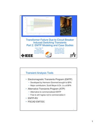
Transformer Failure Due to Circuit Breaker
Induced Switching Transients
Part 2: EMTP Modeling and Case Studies
David D. Shipp, PE
Fellow, IEEE
Eaton Electrical Group
130 Commonwealth Dr.
Warrendale, PA 15086
Thomas J. Dionise, PE
Senior Member, IEEE
Eaton Electrical Group
130 Commonwealth Dr.
Warrendale, PA 15086
2
2
Transient Analysis Tools
• Electromagnetic Transients Program (EMTP)
• Developed by Hermann Dommel brought to BPA
• Major contributors: Scott Meyer & Dr. Liu at BPA
• Alternative Transients Program (ATP)
• Alternative to commercialized EMTP
• Free to all if agree not to commercialize it
• EMTP-RV
• PSCAD EMT/DC
2. 2
3
3
ATP
• ATP Draw interface
• 3-phase modeling
• Solution method - Trapezoidal integration
• Robust for wide variety of modeling needs
• Extensive library of models
• Many options and features
4
4
Source Model
• “3-phase wye cosine”
• Resistance in ohms
• Inductance in mili-Henries
• Source Impedance
• Z1 and X/R
• Z0 and X/R
SYSTEM SOURCE
AT 13.8 KV
XUTIL
RUTIL
VUTIL
UN
U UT
3. 3
5
5
Cable Model
• “Pi Model”
• Resistance in ohms
• Inductance in mili-Henries
• Cable charging in micro-Farads
• ½ charging on sending end
• ½ charning on receiving end
• Multiple pi models in some cases
CABLE
13.8KV
C1 LCABLE
RCABLE C2
C/2C/2
6
6
Breaker Model
• “Switch”
• Time dependent switch
• Open or close at a specific time
• Opens at current zero unless specify otherwise
• Current dependent switch
• Needed for current chopping
• Define current at which to open switch
• Independent Poles (A, B and C independent)
• Data request
• Vacuum or SF6 breaker nameplate
• Current chop (ask manufacturer)
• Transient Recovery Voltage Ratings – T2, E2 and RRV
VCB
BKR
4. 4
7
7
Transformer Model
• “Three Phase Model”
• Resistance in ohms
• Inductance in mili-Henries
• Magnetizing current
• Winding capacitance
• CH and CL for dry-types
• CHL for oil-filled
• More detailed modeling
• Saturation
• Hysteresis
• Data Request
• %Z and X/R, MVA
• BIL
TRANSFORMER
RLRG
LTRAN RTRANT1 T2
CH CL
N:1
8
8
Complete System Model
TRANSFORMER
RLRG
LTRAN
RTRANT1 T2
CH CL
N:1
CABLE
13.8KV
C1 LCABLE
RCABLE C2
C/2C/2
SYSTEM SOURCE
AT 13.8 KV
XUTIL
RUTIL
VUTIL
UN
U UT
VCB
BKR
5. 5
9
9
Time Step
• Time Step – Integration Time Step
• Choice depends on frequency of expected transient
• Too large – miss high frequency effects
• Too small – excessive simulation times
• Nyquist Criteria
• Minimum sample rate = 2 x frequency
• Example 10-20KHz ring for VCB transient
10
10
Switching Transient Simulations
• Switching transient simulations
• EMTP and model requirements
• Case studies
• Data Center
• Ferry Propulsion
• Laddle Melt Furnace
• Successful techniques/solutions
6. 6
11
11
Ferry Propulsion
Highlights
• 60K passengers per day
• 20M passengers per year
• 4160V distribution
• 3 x 2865kW diesel gens
• 2 x 1865KW forward propulsion motors
• 2 x 1865KW reverse propulsion
12
12
Problem
• Forward propulsion drives ferry
• Upon reaching dock, reverse propulsion stops ferry
• July 1, 2009, reverse propulsion was lost entering dock
• lost power and hit a pier at full speed
• one serious injury and nine minor injuries
• 750 to 800 passengers were aboard
• impact did not send any passengers overboard
• 1185KVA rectifier transformer failed on reverse propulsion
motor
• Evidence of insulation failure on first few turns of primary
winding
• Investigation into source of such failure VCB switching
7. 7
13
13
Ferry - Oneline
Vacuum
Breaker
Short
Cable
Dry-Type
Transformer
Forward Reverse
14
14
Ferry – Electrical Highlights
• 3 x 2865kW diesel generators
• 4160V, 3-bus system
• Vacuum circuit breakers – 630A mains, ties,
feeders
• 2 x 1865kW motors (forward propulsion)
• 2 x 1865kW motors (reverse propulsion)
• 8 x 1185KVA dry-type transformers, 30kV BIL
• 3-winding rectifier transformers
• 12-pulse effective (6-pulse VFD per winding)
• Feeder cable lengths of 50 feet each
8. 8
15
15
Worst Case Scenarios
• Feeder cable lengths of 50 feet
• Each 1185KVA transformer has one 4160V feeder
• Need to examine both feeders for each transformer
• “Worst Case” Switching Transient Simulations
• Close 4160V VCB to transf. with 50ft. cable (model validation)
• Close 4160V VCB to transf. with 50ft. cable (re-ignition)
• Open 4160V VCB to transf. with 50ft. cable (current chop)
• Repeat each case with Snubber
16
16
Measurements
Transient Overvoltages at Primary of Rectifier Transformer – VCB Closes
9. 9
17
17
Study Cases
• Case 1 – Closing the 4.16 kV feeder breaker feeding the three
winding rectifier transformer with the distance of 50 feet.
Simulated to match the Siemens measurements to ensure that
the computer model is accurate. (Model Validation)
• Case 2 – Same as Case 1, except with the RC snubber.
• Case 3 - Closing the 4.16 kV feeder breaker feeding the three
winding rectifier transformer, then the 4.16 kV feeder breaker
opens during the inrush current. Shows the possibility of the
vacuum breaker re-ignition. (Re-ignition)
• Case 4 - Same as Case 3, except with the RC snubber.
• Case 5 - Open the 4.16 kV feeder breaker feeding the three
winding rectifier transformer under the light load condition.
(Current Chop)
• Case 6 – Same as Case 5, except with the RC snubber.
18
18
Case 1 – Model Validation
Transformer primary voltage
V max of 4.96kV < 30kV BIL
Oscillation of 20,203Hz > 1000Hz
10. 10
19
19
Case 2 – Valid Model with Snubber
Transformer primary voltage
V max of 3.982kV < 30kV BIL
Oscillation of < 1000Hz
20
20
Case 3 – Re-ignition
Transient Recovery Voltage (TRV) at VCB
11. 11
21
21
Case 4 – Re-ignition with Snubber
Transient Recovery Voltage (TRV) at VCB
22
22
Case 5 – Current Chop
Transformer primary voltage
V max of 31.9kV > 30kV BIL
Oscillation of 958Hz ~ 1000Hz
12. 12
23
23
Case 6 – Current Chop with Snubber
Transformer primary voltage
V max of 8.9kV < 30kV BIL
Oscillation of 299Hz < 1000Hz
24
24
Summary of Current Chop Cases
13. 13
25
25
Summary of Re-Ignition Cases
26
26
Recommendations
• Install snubber at primary of each 1185KVA
rectifier transformer
• 40ohm resistor
• Non-inductive
• Peak voltage – 6 kVpeak
• Peak energy – 2100 Joules
• Average power – 190 Watt
• 0.5uF capacitor
• Rated voltage - 4.16kV
14. 14
27
27
Data Center
Highlights
• Tier III
• LEEDS Certified
• 12.5MVA Capacity
• 13.2KV Ring Bus
28
28
Data Center - Oneline
Vacuum
Breaker
Short
Cable
Cast-Coil
Transformer
15. 15
29
29
Data Center – Electrical Highlights
• 2 x 24.9 kV lines from Factory Shoals and Buzzard
Roast
• 2 x 12.5 MVA transformers
• 13.2 kV “ring-bus” configuration
• MSA and MSB and generator bus GPS
• Vacuum circuit breakers – 600A mains & ties, 200A feeders
• 3 x 2250 KW generators
• 6 x 3750KVA cast coil transformers, 90kV BIL
• 3 x DE Subs CSA, CSB and CSC
• 3 x SE Subs MDSA, MDSB and MLB
• Feeder cable lengths vary from 109 to 249 Feet
30
30
Worst Case Scenario
• Feeder cable lengths vary from 109 to 249 Feet
• Each 3750KVA transformer has two 13.2kV feeders
• Need to examine both feeders for each transformer
• Shortest of all 13.2kV cable runs to 3750KVA
Transformers
• MSB to Transformer CSC – 109 feet
• MSA to Transformer CSC – 111 feet
• “Worst Case” Switching Transient Simulation
• Open 13.2 kV VCB at MSB to CSC with 109ft. cable
• Open 13.2 kV VCB at MSA to CSC with 111ft. cable
16. 16
31
31
Worst Case – Study Case 13
• Study Case 13 - Open the 13.2 kV feeder breaker at
Bus MSB feeding the 3,750 kVA dry type transformer
CSC with the shorter distance of 109 feet. The result
for this case will represent the “worst-case” condition,
the other feeder from Bus MSA has a longer feeder
distance of 111 feet.
• Study Case 14 – Same as Case 13, except with the
application of the 0.25 μF surge capacitor.
• Study Case 15 – Same as Case 13, except with the
application of the snubber circuit with 30ohm and 0.25
μF surge capacitor.
32
32
Case 13 – no surge protection
Load current at 13.2kV VCB
Load current of 10A
Chopped current of 6A
17. 17
33
33
Case 13 – no surge protection
Transformer CSC primary voltage
VC max of 65.3kV > 95kV BIL
VB max of 116kV > 95kV BIL
VA max of 123kV > 95kV BIL
Oscillation of 969Hz > 1000Hz
34
34
Case 14 – 0.25uF surge cap
Load current at 13.2kV VCB
Load current of 10A
Chopped current of 6A
18. 18
35
35
Case 14 – 0.25uF surge cap
Transformer CSC primary voltage
VA max of 29.4kV < 95kV BIL
VB max of 19.1kV < 95kV BIL
VC max of 15.7kV < 95kV BIL
Oscillation of 215Hz < 1000Hz
36
36
Case 15 – snubber 30ohm and 0.25uF
Load current at 13.2kV VCB
Load current of 10A
Chopped current of 6A
19. 19
37
37
Case 15 – snubber 30ohm and 0.25uF
Transformer CSC primary voltage
VB max of 28.6kV < 95kV BIL
VA max of 19.4kV < 95kV BIL
VC max of 15.9kV < 95kV BIL
Oscillation of 215Hz < 1000Hz
38
38
Case 15 – snubber 30ohm and 0.25uF
Snubber Current – important for duty on resistor and capacitor
IC peak of 7.7A
IB peak of 8.0A
IA peak of 6.8A
21. 21
41
41
Recommendations
• Install snubber at primary of each 3750KVA cast coil
transformer 30ohm and 0.25uF
• Install surge caps 0.25uF at each emergency
generator
• Install surge arresters at the following locations:
• both incoming power transformers
• every distribution dry type transformer
• every generator
• line side of both main circuit breakers
• line side of the three generator circuit breakers
• load side of every feeder breaker and every tie circuit breaker
42
42
Laddle Melt Furnace
Highlights
• Retiring 3 x 38MW EAFs
• Adding 1 x 155MVA EAF
• Adding 2 x 138kV lines to new EAF
• Adding SVC at 34.5kV
• Adding 1 x 20MW LMF
22. 22
43
43
LMF & EAF - Oneline
Vacuum
Breaker
Short
Bus
Oil-Filled
Transformer
Existing
EAF New
LMF
44
44
138KV
UTILITY
4713MVA 3PH SC
9.26 X/R
50/66/83MVA
135.3/26.4KV
7.5%Z
SF-6 BREAKER
2000A
1600A
27KV
13OHM
AUTO LTC
56MVA
27-10KV
3.3%Z
ALUMINUM
IPS BUS
53FEET
VACUUM BREAKER
1200A
LMF XFMR
50/56MVA
25/.53KV
2.5%Z
HEAVY DUTY
COPPER PIPE
28FEET
LMF
20MW
LMF
Vacuum
Breaker
Short
Bus
Oil-Filled
Furnace
Transformer
New
LMF
SF6
Breaker
Short
Bus
Oil-Filled
Auto-Regulating
Transformer
23. 23
45
45
LMF Circuit – Electrical Highlights
• 50MVA Power Transformer 135/26.4kV
• 27kV system
• SF6 circuit breaker – 2000A
• Bus length of 53 feet
• 56MVA autoregulating transformer, 200kV BIL
• Vacuum circuit breaker – 1200A
• Bus length of 28 feet
• 50MVA oil-filled LMF transformer, 200kV BIL
• 20MW LMF
46
46
Worst Case Scenarios
• Examine switching transients at both transformers
• “Worst Case” Switching Transients for Auto-Reg Transf
• Open SF6 breaker to transf. with 53ft. bus (6A current chop)
• 3 cycles after energizing Auto-Reg Tran, open SF6 bkr to transf.
with 53ft. bus (re-ignition) highly inductive current
• “Worst Case” Switching Transients for LMF Transf
• Open VCB to transf. with 28ft. bus (6A current chop)
• 3 cycles after energizing LMF Tran, open VCB to transf. with
28ft. bus (re-ignition) highly inductive current
• Repeat each case with Snubber
24. 24
47
47
Case 1 – Open VCB
LMF Transformer primary voltage
V max of 386kV > 200kV BIL
Oscillation of 1217Hz > 1000Hz
48
48
Case 2 – Open VCB with Snubber
LMF Transformer primary voltage
V max of 56.4kV < 200kV BIL
Oscillation of 200Hz < 1000Hz
25. 25
49
49
Case 3 – Open SF6 Breaker
Auto-regulating Transformer primary voltage
V max of 23kV < 200kV BIL
No oscillating frequency
50
50
Case 4 – Open SF6 Breaker with Snubber
Auto-regulating Transformer primary voltage
VB max of 54.7kV < 200kV BIL
Oscillation of 197Hz < 1000Hz
26. 26
51
51
Case 5 – VCB Re-ignition
Transient Recovery Voltage for VCB
52
52
Case 5 – Highly Inductive Current
Inrush current to LMF transformer
6000A Peak
Inrush
VCB
Opens
VCB
Closes
27. 27
53
53
Case 6 – VCB Re-ignition & Snubber
Transient Recovery Voltage for VCB
54
54
Case 7 – SF6 Breaker Re-ignition
Transient Recovery Voltage for Siemens SF6
28. 28
55
55
Case 7 – Highly Inductive Current
Inrush current to Auto-Regulating transformer
14000A Peak
Inrush
SF6 CB
Opens
SF6 CB
Closes
56
56
Case 8 – SF6 Breaker Re-ignition & Snubber
Transient Recovery Voltage for SF6 Breaker