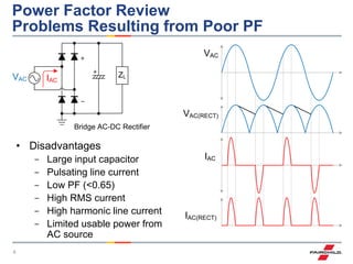
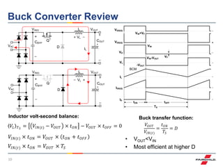
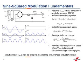
Current Shaping Strategies
for Buck Power Factor Correction
Steve Mappus and Hangseok Choi
2
Agenda
• PFC review
• Harmonics review
• Boost converter
• Buck converter
- K-value
• Sine-squared modulation
- Harmonic analysis
• Sine modulation
- Harmonic analysis
• 300 W dual interleaved buck PFC reference design
- Test results
• Summary
3
Power Factor (PF) Review Definition of PF
and Total Harmionic Distortion (THD)
V
I
Distortion factor < 1
Displacement factor = 1
PF < 1
(c)
cos(1)
V
I
Distortion factor = 1
Displacement factor < 1
PF < 1
I leads V = capacitive
V
I
Distortion factor = 1
Displacement factor = 1
PF = 1
Pure resistive load
 1
1
2
1
cos
2
2 




n
nRMSRMS
avg
I
I
IV
P
(VA)PowerApparent
(W)PowerReal
PF
Displacement Factor
Distortion Factor
Real Power (W)
Apparent Power (VA)
Reactive
Power (VAR)
φ1
Capacitive
Inductive
1
2
2
I
I
THD n
n



2
1
1
THD
factorDistortion


4
Power Factor Review
Problems Resulting from Poor PF
Bridge AC-DC Rectifier
• Disadvantages
- Large input capacitor
- Pulsating line current
- Low PF (<0.65)
- High RMS current
- High harmonic line current
- Limited usable power from
AC source
ZLVAC IAC
VAC
VAC(RECT)
IAC
IAC(RECT)
5
Power Factor Review
AC Line Current: Non-PFC vs. PFC
Load
or
DC-DC
VAC IAC
Load
or
DC-DC
VAC IAC PFC
• Non-PFC vs. PFC
- Non-PFC shows 5~6 times higher peak current
- Non-PFC shows more harmonic current components
0%
20%
40%
60%
80%
100%
100%
91%
73%
52%
32%
19%
15% 15% 13%
9%
1 3 5 7 9 11 13 15 17 19
HarmonicAmplitude(%Fund)
Harmonic Number (n)
THD = 136%
Distortion Factor = 59%
6
Harmonics Review
100
Ts=0.01sec
2
2s s
s
f
T

  
1 3 5 7
100 4 100 4 100 4 100 4
( ) sin( ) sin(3 ) sin(5 ) sin(7 )....
3 5 7
.....
s s s sf t t t t t
V V V V
   
   
   
   
    
Any periodic signal can be expressed as a Fourier Series
The term with frequency fs is called the fundamental
The terms with frequencies that are multiples of fs are called harmonics
harmonics
7
Harmonics Review
1
1
( ) sin( ) :
( ) sin( )n n
n
V t V t Pure AC voltage
i t I nt

 



 
Load
i(t)
v(t)
0
10
1
1
( ) ( ) ( )
1
{ sin( )[ sin( )]}
T
av
T
n n
n
P t v t i t dt
T
V t I nt dt
T
  



 


1 1
1( ) cos( )
2
av
V I
P t  
Harmonic currents from an energy transfer point of view
Net energy is transmitted to the load only when the Fourier Series of v(t) and
i(t) contains terms at the same frequency
For a sinusoidal voltage v(t), harmonics of i(t) are not involved in energy
transfer (just circulating)
0
sin( )sin( ) 0 ( 1)
T
nt nt dt if n    
8
EN61000-3-2
(input current <16 A per phase)
• Class A: Absolute limits
- 3-phase equipment and all other
equipment, except that stated in other
classes
• Class B: Absolute limits
- Least restrictive
- Portable tools used for short-time
- Limits are 1.5 times higher than class A
• Class C: Relative limit (lighting
equipment, PIN>25 W)
- The most restrictive because high
percentage of the total load is lighting
- PF is included in the limits
- Equipment with power below 25 W is
excluded
• Class D: Relative and absolute limits
(75 W<PIN<600 W)
- PC, PC monitors or TV receivers
Harmonics Class A Class B Class C Class D
A (rms) A (rms) % A
(rms)
mA/W
3 2.30 3.45 30×PF 2.30 3.40
5 1.44 2.16 10 1.14 1.90
7 0.77 1.15 7 0.77 1.00
9 0.40 0.60 5 0.40 0.50
11 0.33 0.49 3 0.33 0.35
13 0.21 0.31 3 0.21 0.29
15 to 39 1.2/n 1.8/n 3 1.2/n 3.85/n
2 1.08 1.62 2
4 0.43 0.64
6 0.30 0.45
8 to 40 1.84/n 2.76/n
9
Boost Converter Review
VGS(Q)
VDS(Q)
IL
IDS(Q)
ID
VOUT
BCM
tON tOFF
TS
𝑉𝐼𝑁(𝑡) × 𝑡 𝑂𝑁 + 𝑡 𝑂𝐹𝐹 = 𝑉𝑂𝑈𝑇 × 𝑡 𝑂𝐹𝐹
𝑉𝐼𝑁(𝑡) × 𝑇𝑆 = 𝑉𝑂𝑈𝑇 × 𝑡 𝑂𝐹𝐹
𝑉𝑂𝑈𝑇
𝑉𝐼𝑁(𝑡)
=
𝑇𝑆
𝑡 𝑂𝐹𝐹
=
1
1 − 𝐷
Inductor volt-second balance:
Boost transfer function:
• VOUT>VIN
• Most efficient at lower D
• Continuous input current
• CCM, BCM, DCM modes
• High PF, low THD
VOUT
VAC
VIN(t)
D
IL
L
VL
Q
COUTCBYP
VOUT
VAC
VIN(t)
D
IL
L
VL
Q
COUTCBYP
𝑉𝐿 𝑇 𝑆
= 𝑉𝐼𝑁(𝑡) × 𝑡 𝑂𝑁 + 𝑉𝐼𝑁(𝑡) − 𝑉𝑂𝑈𝑇 × 𝑡 𝑂𝐹𝐹 = 0
10
Buck Converter Review
VOUT
VAC
VIN(t)
D
VOUT
VAC
VIN(t)
D
IL
Q
L
VL
L
VL
Q COUTCBYP
COUTCBYP
VGS(Q)
VD
VDS(Q)
IL
IDS(Q)
ID
VIN
VF
VL
-VOUT
VIN-VOUT
VIN+VF
BCM
tON tOFF
TS
𝑉𝐿 𝑇 𝑆
= 𝑉𝐼𝑁(𝑡) − 𝑉𝑂𝑈𝑇 × 𝑡 𝑂𝑁 − 𝑉𝑂𝑈𝑇 × 𝑡 𝑂𝐹𝐹 = 0
𝑉𝐼𝑁(𝑡) × 𝑡 𝑂𝑁 = 𝑉𝑂𝑈𝑇 × 𝑡 𝑂𝑁 + 𝑡 𝑂𝐹𝐹
𝑉𝐼𝑁(𝑡) × 𝑡 𝑂𝑁 = 𝑉𝑂𝑈𝑇 × 𝑇𝑆
𝑉𝑂𝑈𝑇
𝑉𝐼𝑁(𝑡)
=
𝑡 𝑂𝑁
𝑇𝑆
= 𝐷
Inductor volt-second balance: Buck transfer function:
• VOUT<VIN
• Most efficient at higher D
11
Buck Converter PFC
• Advantages
- Higher low-line efficiency
- Lower CM noise due to lower VOUT
- Lower VOUT to downstream DC-DC (two-stage designs)
- Smaller PFC inductor
- “Free” inrush current protection
• Challenges
- High-side, high-voltage, gate drive
- VOUT<VIN→holdup ∝ VOUT
2
- Pulsed input current
- Increased current harmonic distortion
- Proper selection of VOUT to meet harmonic specifications
12
Buck Converter PFC
Typical Applications – Where Does it Fit?
• 25 W<POUT<500 W
• Low-line, 115 VAC
- VOUT<68 V, Class C (lighting)
- VOUT<95 V, Class D (computing)
• High-line, 230 VAC
- VOUT<136 V, Class C (lighting)
- VOUT<191 V, Class D (computing)
• Applications examples
- Adaptors
- Battery chargers
- LED lighting
- Motion control
- Computing
13
K-Value and Conduction Angle
| VAC |
VOUT
θz0 π- θz π
IAC
VAC
θ
t
• K-value definition
• Conduction angle vs. K-value
𝐾 =
𝑉𝑂𝑈𝑇
2 × 𝑉𝐴𝐶
• K-value determines:
- Efficiency
- Conduction angle
- PF
- THD𝜃 𝐶(%) =
2
𝜋
× cos−1
(𝐾)
14
Sine-Squared Modulation Fundamentals
IAC
EMI filter
VAC
VOUT
IL
AVG
VAC
IAC
PAC
VOUT
IL
AVG
PO.CAP
𝑃𝑂𝐶𝐴𝑃 𝑡 = 𝑖 𝐿
𝐴𝑉𝐺
(𝑡) × 𝑉𝑂𝑈𝑇
• Instantaneous input power
• Instantaneous output power
• Average inductor current
Input current (IAC) can be shaped by shaping the average inductor current
• Assume VOUT small, conduction
angle large (near 100%)
• Need to address practical cases
when VOUT is large and
conduction angle not negligible
15
Sine-Squared Modulation
CCM Control Method
VOUTQ L
IL
VAC
S
R
Q
Q
+
-
VREF
VEA
IAC
VIN VOUT
IL
VIN
TON
doulbler
IDS
+
-
OSC
VIREF
VGS
Q
RCSIDS
VIREF
θz π-θz π
RCS
RCSIDS
2
( )IN OUT
OUT
V V
V

(VIN-VOUT)2
VOUT
2
𝐼𝐴𝐶 𝜃 = 𝑖 𝐿
𝐴𝑉𝐺
𝜃 × 𝐷 𝜃
= 𝑖 𝐿
𝐴𝑉𝐺
𝜃 ×
𝑉𝑂𝑈𝑇
𝑉𝐴𝐶 × sin 𝜃
𝑓𝑜𝑟: 𝜃 𝑍 < 𝜃 < 𝜋 − 𝜃 𝑍
:0, otherwise
=
𝑉𝐸𝐴 × sin 𝜃 − 𝐾 2
𝑅 𝐶𝑆 × 𝐾 × sin 𝜃
,
• Average inductor current
• AC line current
𝑓𝑜𝑟: 𝜃 𝑍 < 𝜃 < 𝜋 − 𝜃 𝑍
:0, otherwise
16
Sine-Squared Modulation
K-Value, Input Current
0
0.2
0.4
0.6
0.8
1
1.2
/ 2
K=0.1
K=0.2
K=0.3
K=0.4
K=0.5
• K increases→conduction angle
decreases
• K impact on harmonic distortion:
𝐼 𝐻 𝑛 =
2
𝜋
𝐼𝐿𝐼𝑁𝐸 ∙ sin 𝜃 − 𝐾 2
sin(𝜃)
sin⁡(𝑛𝜃) 𝑑𝜃
𝜋−𝜃 𝑍
𝜃 𝑍
𝐼 𝐻 𝑛
𝐼 𝐻 1
=
sin 𝜃 − 𝐾 2
sin(𝜃)
sin⁡(𝑛𝜃) 𝑑𝜃
𝜋−𝜃 𝑍
𝜃 𝑍
sin 𝜃 − 𝐾 2 𝑑𝜃
𝜋−𝜃 𝑍
𝜃 𝑍
× 100%
• Amplitude of harmonic current
relative to fundamental
Normalized input current (IAC) for various K-values
• Even harmonics are 0
• Odd harmonics calculated and
plotted using software
17
Sine-Squared Modulation
Current Harmonic Content
5th Harmonics
7th9th
Class C Limit for 7th (7%)
Class C Limit for 9th (5%)
0%
5%
10%
15%
20%
25%
30%
35%
40%
45%
50%
0 0.1 0.2 0.3 0.4 0.5
K
Class C Limit for 3rd (30%)
3rd Harmonics
Class D Limit for 3rd (39.1%)
Class C Limit for 5th (10%)
13th15th
17th
19th
21st
0.0%
0.5%
1.0%
1.5%
2.0%
2.5%
3.0%
0 0.1 0.2 0.3 0.4 0.5
K
Class C Limit for 11th, 13th, 15th, 17th, 19th, 21st (3%)
11th
Class D Limit for 17th (2.6%)
Class D Limit for 19th (2.3%)
Class D Limit for 21st (2.1%)
• 3rd, 5th, 7th and 9th harmonics
• 3rd harmonic increases
monotonically with K, defines Class
C and Class D K-value limits
• 11th, 13th, 15th, 17th, 19th and 21st
harmonics
• All are well below limits
18
Sine-Squared Modulation
EN61000-3-2, K-Value Limits
0
40
80
120
160
200
240
280
320
360
400
0%
10%
20%
30%
40%
50%
60%
70%
80%
90%
100%
0 0.2 0.4 0.6 0.8 1
VOUT(V)
ConductionAngle(%)
K (VOUT/√2×VRMS)
K Value,Sine2 Modulation
CLASS C
0.33
CLASS D
0.42
230VRMS
115VRMS
Cond
Angle
• Class C
- K<0.33
- Could be cost effective single-stage solution for LED lighting
• Class D
- K<0.42
- Difficult to meet hold-up
Efficiency UpTHD Down
19
Sine Modulation
CCM Control Method
VOUTQ L
IL
VAC
S
R
Q
Q
+
-
VREF
VEA
IAC
VIN VOUT
IL
VIN
VIN-VOUT
TON
doulbler
IDS
+
-
OSC
θz π-θz π
VIREF
RCS
RCSIDS
IN OUT
OUT
V V
V

VOUT
VGS
Q
RCSIDS
VIREF
𝑓𝑜𝑟: 𝜃 𝑍 < 𝜃 < 𝜋 − 𝜃 𝑍
:0, otherwise
𝐼𝐴𝐶 𝜃 = 𝑖 𝐿
𝐴𝑉𝐺
𝜃 × 𝐷 𝜃
= 𝑖 𝐿
𝐴𝑉𝐺
𝜃 ×
𝑉𝑂𝑈𝑇
𝑉𝐴𝐶 × sin 𝜃
𝑓𝑜𝑟: 𝜃 𝑍 < 𝜃 < 𝜋 − 𝜃 𝑍
:0, otherwise
=
𝑉𝐸𝐴 × 𝑠𝑖𝑛 𝜃 − 𝐾
𝑅 𝐶𝑆 × sin 𝜃
,
• Average inductor current
• AC line current
20
Sine Modulation
K-Value, Input Current
• K increases→conduction angle
decreases
• K impact on harmonic distortion:
• Amplitude of harmonic current
relative to fundamental
Normalized input current (IAC) for various K-values
• Even harmonics are 0
• Odd harmonics calculated and
plotted using software
0
0.2
0.4
0.6
0.8
1
1.2
/ 2
K=0.1
K=0.2
K=0.3
K=0.4
K=0.5
K=0.6
𝐼 𝐻 𝑛 =
2
𝜋
𝐼𝐿𝐼𝑁𝐸 × 𝐾 sin 𝜃 − 𝐾
sin(𝜃)
sin⁡(𝑛𝜃) 𝑑𝜃
𝜋−𝜃 𝑍
𝜃 𝑍
𝐼 𝐻 𝑛
𝐼 𝐻(1)
=
sin 𝜃 − 𝐾
sin(𝜃)
sin⁡(𝑛𝜃) 𝑑𝜃
𝜋−𝜃 𝑍
𝜃 𝑍
sin 𝜃 − 𝐾 𝑑𝜃
𝜋−𝜃 𝑍
𝜃 𝑍
× 100%
21
Sine Modulation
Current Harmonic Content
• 3rd and 5th harmonics • 7th and 9th harmonics
0%
5%
10%
15%
20%
25%
30%
35%
40%
45%
0 0.1 0.2 0.3 0.4 0.5 0.6
K
Class C limit for 3rd
(30%)
3rd
harmonics
Class D limit for 3rd
(39.1%)
Class C limit for 5th
(10%)
Class D limit for 5th
(21.9%)
5th
harmonics
0%
2%
4%
6%
8%
10%
12%
14%
0 0.1 0.2 0.3 0.4 0.5 0.6
K
Class D limit for 7th
(11.5%)
7th
harmonics
9th
harmonics
Class D limit for 9th
(5.8%)
Class C limit for 7th
(7%)
Class C limit for 9th
(5%)
22
Sine Modulation
Current Harmonic Content
• 11th and 13th harmonics • 15th, 17th, 19th and 21st harmonics
11th
harmonics
13th
harmonics
Class C limit
For 11th
, 13th
(3%)
Class D limit
For 13th
(3.4%)
Class D limit
For 11th
(4%)
Class C limit
For 15th
, 17th
, 19th
, 21th
(3%)
Class D limit
For 15th
(3%)
Class D limit For 17th
(2.6%)
Class D limit For 19th
(2.3%)
Class D limit For 21st
(2.1%)
15th
17th
19th
21st
23
Sine Modulation
EN61000-3-2, K-Value Limits
• Class C
- 0.09<K<0.12
- Not feasible for meeting Class C
• Class D
- 0.22<K<0.59
- Upper K-value limit extended from 0.42 (sine-squared modulation) to 0.59
0
40
80
120
160
200
240
280
320
360
400
0%
10%
20%
30%
40%
50%
60%
70%
80%
90%
100%
0 0.2 0.4 0.6 0.8 1
VOUT(V)
ConductionAngle(%)
K (VOUT/√2×VRMS)
K Value, Sine Modulation
CLASS D
0.22 0.590.09 0.12
CLASS C
230VRMS
115VRMS
Cond
Angle
Efficiency UpTHD Down
24
Sine-Squared Modulation
BCM Control Method
VOUTQ L
IL
VAC
S
R
Q
Q
+
-
VREF
VEA
VIN
+
-
OSC
ZCD
Turn-on Determined by ZCD
VGS
No ZCD No ZCD
| VAC |
VOUT
VAC
t
t
IDS
θz0 π- θz π
IDS(AVG)
IDIAC
θ
IDS
VIN-VOUT
𝑓𝑜𝑟: 𝜃 𝑍 < 𝜃 < 𝜋 − 𝜃 𝑍
:0, otherwise
𝑖 𝐿
𝐴𝑉𝐺
𝜃 =
𝑡 𝑂𝑁
2 × 𝐿
× 𝑉𝐼𝑁(𝑅𝑀𝑆) × sin 𝜃 − 𝐾 ,
𝑓𝑜𝑟: 𝜃 𝑍 < 𝜃 < 𝜋 − 𝜃 𝑍
:0, otherwise
𝐼𝐴𝐶 𝜃 =
𝑡 𝑂𝑁 × 𝑉𝑂𝑈𝑇 × sin 𝜃 − 𝐾
2 × 𝐿 × sin 𝜃
,
𝐼 𝐻 𝑛 =
2
𝜋
𝑡 𝑂𝑁 × 𝑉𝑂𝑈𝑇 sin 𝜃 − 𝐾
2 × L × sin(𝜃)
sin⁡(𝑛𝜃) 𝑑𝜃
𝜋−𝜃 𝑍
𝜃 𝑍
Not implemented in
commercially available
BCM PFC controllers
25
Sine Modulation
BCM Control Method
• Repeated From Previous Sine-Squared
Modulation:
VOUTQ L
IL
VAC
S
R
Q
Q
+
-
VREF
VEA
VIN
+
-
OSC
ZCD
Turn-on Determined by ZCD
VGS
No ZCD No ZCD
| VAC |
VOUT
VAC
t
t
IDS
θz0 π- θz π
IDS(AVG)
IDIAC
θ
IDS
𝑓𝑜𝑟: 𝜃 𝑍 < 𝜃 < 𝜋 − 𝜃 𝑍
:0, otherwise
𝑖 𝐿
𝐴𝑉𝐺
𝜃 =
𝑡 𝑂𝑁
2 × 𝐿
× 𝑉𝐼𝑁(𝑅𝑀𝑆) × sin 𝜃 − 𝐾 ,
𝑓𝑜𝑟: 𝜃 𝑍 < 𝜃 < 𝜋 − 𝜃 𝑍
:0, otherwise
𝐼𝐴𝐶 𝜃 =
𝑡 𝑂𝑁 × 𝑉𝑂𝑈𝑇 × sin 𝜃 − 𝐾
2 × 𝐿 × sin 𝜃
,
𝐼 𝐻 𝑛 =
2
𝜋
𝑡 𝑂𝑁 × 𝑉𝑂𝑈𝑇 sin 𝜃 − 𝐾
2 × L × sin(𝜃)
sin⁡(𝑛𝜃) 𝑑𝜃
𝜋−𝜃 𝑍
𝜃 𝑍
26
Buck PFC Implementation
VOUTQ L
VAC
VIN(t)
(a)
VOUTQ L
VAC
VIN(t)
(b)
PWM
HS
VOUT
Q L
VAC
VIN(t)
VOUT
Q
LVAC
VIN(t)
VSNS
PWM
(a)
(b)
Conventional AC-DC buck
• High-side gate drive
• “Slow” feedback loop
• Direct VOUT sensing
Inverted AC-DC buck
• Low-side gate drive
• Floating output
• Differential VOUT sensing
27
Buck PFC Implementation
Differential VOUT SensingQ L
VAC
VOUT
Q
LVAC
VIN(t)
VSNS
PWM
(a)
(b)
• VOUT level shift necessary
• Simple PNP voltage divider
Bias, transistor level shifter
• Assume ib<<(VOUT-Vb)/R1
VOUT
Q
LVAC
VIN(t)
PWM
VSNS
R4
R1
R2
R3
500V
SOT23
VREF
𝑉𝑏 =
𝑅2
𝑅1 + 𝑅2
𝑉𝑒 = 𝑉𝑏 + 𝑉𝑏𝑒
𝑖 𝑒 =
𝑉𝑜𝑢𝑡 − 𝑉𝑒
𝑅3
≈ 1𝑚𝐴
𝑅4 =
𝑉𝑅𝐸𝐹
𝑖 𝑒
For two-stage design, downstream DC-DC must handle floating bus voltage
28
Reference Design Using Sine Modulation
Interleaved BCM Buck PFC
• Design specification:
• Design goals:
1. High efficiency, especially low-line
2. Verify theoretical K-value limits
3. Meet EN61000-3-2, Class D
4. Use interleaving to reduce EMI
29
Interleaved BCM Buck PFC Converter
ZCD2
PFC
Controller
AC
Line
VOUT
Q1
Q2
ZCD1
L2
L1
IDS1
IDS2
IL2
IL1
IL1,IL2
IDS1,IDS2
VLINE
• Output ripple current cancellation at
twice the effective frequency→lower
COUT RMS current
• Input RMS ripple current can be
same as CCM at twice the effective
frequency when interleaving
• Can be applied to high power above
150 W without concern about EMI
filter
Turn-on determined by ZCD1
VGS1
No ZCD1 No ZCD1
| VAC |
VOUT
IDS1
θz0 π- θz π
IDS1(AVG)
IAC1
VAC
θ
t
t
VGS2
Turn-on determined by ZCD2No ZCD2 No ZCD2 t
IDS2
θz0 π- θz π
IDS2(AVG)
IAC2
θ
30
Dual Interleaved BCM Buck PFC Schematic
31
Interleaved BCM Buck PFC
CH1 = VIN(AC), CH2 = IIN(AC), CH3 = IL2, CH4 = IL1
• VIN(AC) = 115 VRMS
- K = 0.55
- VOUT = 90 V
- POUT = 300 W
• VIN(AC) = 230 VRMS
- K = 0.28
- VOUT = 90 V
- POUT = 300 W
32
Interleaved BCM Buck PFC
CH1 = VGS(OUT1), CH2 = VGS(OUT2), CH3 = IDS1, CH4 = IDS2
• Phase adding, 1→2
- VIN(AC) = 115 VRMS
- K = 0.55
- VOUT = 90 V
- POUT = 48 W (16% POUT(MAX))
• Phase shedding, 2→1
- VIN(AC) = 115 VRMS
- K = 0.55
- VOUT = 90 V
- POUT = 37 W (11% POUT(MAX))
33
Interleaved BCM Buck PFC
CH1 = VGS(OUT1), CH2 = VGS(OUT2), CH3 = IL2, CH4 = IL1
• Interleaving (steady state)
- VIN(AC) = 115 VRMS
- K = 0.55
- VOUT = 90 V
- POUT = 300 W
- F = 42 kHz
• Interleaving (restart timer)
- VIN(AC) = 115 VRMS
- K = 0.55
- VOUT = 90 V
- POUT = 300 W
- F = 16 kHz
34
Interleaved BCM Buck PFC
Inrush Current, Soft-Start
• Startup (No Inrush Spike)
- CH1 = VIN(AC), CH2 = IIN(AC)
- VIN(AC) = 115 VRMS
- K = 0.55
- VOUT = 90 V
- POUT = 300 W
- Higher initial current →charging output capacitor
• Startup (Soft-Start)
- CH1 = VOUT, CH2 = IC(OUT)
- VIN(AC) = 115 VRMS
- K = 0.55
- VOUT = 90 V
- POUT = 300 W
- tRISE = 100 ms
35
Interleaved BCM Buck PFC
Efficiency
90%
95%
100%
0% 10% 20% 30% 40% 50% 60% 70% 80% 90% 100%
Efficiency(%)
Output Power (%)
Interleaved Buck PFC, Efficiency vs. Load
(90VOUT,100%=300W)
115Vrms
230Vrms
90%
95%
100%
85 105 125 145 165 185 205 225 245 265
Efficiency(%)
AC Line Voltage (VRMS)
Interleaved Buck PFC, Efficiency vs. AC Line
(90VOUT,300W)
90Vout
80Vout
• VIN(AC) = 115 VRMS
- K = 0.55 (Limit<0.59)
- VOUT = 90 V (VLIMIT<95 V)
• VIN(AC) = 230 VRMS
- K = 0.28 (Limit<0.59)
- VOUT = 90 V (VLIMIT<191 V)
• Efficiency increase as VOUT increases
• Buck operates more efficiently at
higher D
- POUT = 300 W
36
Interleaved BCM Buck PFC
EN61000-3-2, Current Harmonics
0
0.2
0.4
0.6
0.8
1
1.2
3 5 7 9 11 13 15 17 19 21 23 25 27 29 31 33 35 37 39
HarmonicCurrent(A)
Harmonic Number
Interleaved Buck PFC
EN61000-3-2, Class D, 115VAC, 90VOUT, 300W, K=0.55
MeasuredHarmonic Current
Class D (Computing) Limit
0
0.2
0.4
0.6
0.8
1
1.2
3 5 7 9 11 13 15 17 19 21 23 25 27 29 31 33 35 37 39
HarmonicCurrent(A)
Harmonic Number
Interleaved Buck PFC
EN61000-3-2, Class D, 230VAC, 90VOUT, 300W, K=0.28
MeasuredHarmonic Current
Class D (Computing) Limit
• VIN(AC) = 115 VRMS
- K = 0.55 (KLIMIT<0.59)
- VOUT = 90 V (VLIMIT<95 V)
- POUT = 300 W
- K≈KLIMIT
- Barely passes class D
• VIN(AC) = 230 VRMS
- K = 0.28 (KLIMIT<0.59)
- VOUT = 90 V (VLIMIT<191 V)
- POUT = 300 W
- K<<KLIMIT
- Easily passes Class D (↓η)
37
Interleaved BCM Buck PFC
PF
0.50
0.55
0.60
0.65
0.70
0.75
0.80
0.85
0.90
0.95
1.00
0% 10% 20% 30% 40% 50% 60% 70% 80% 90% 100%
PF
Output Power (%)
Interleaved Buck PFC, PF vs. Load
(90VOUT, 100%=300W)
115Vrms
230Vrms
0.8
0.82
0.84
0.86
0.88
0.9
0.92
0.94
0.96
0.98
1
85 105 125 145 165 185 205 225 245 265
PF
AC Line Voltage (VRMS)
Interleaved Buck PFC, PF vs. AC Line
(POUT=300W)
90Vout
80Vout
• PF>0.9 for 115 VRMS,
20%<POUT<100%
• PF increases as VOUT (K-value)
decreases
• Conduction angle increases as VOUT
(K-value) decreases, less crossover
distortion
- POUT = 300 W
38
Interleaved BCM Buck PFC
THD
0%
5%
10%
15%
20%
25%
30%
35%
40%
45%
50%
10% 20% 30% 40% 50% 60% 70% 80% 90% 100%
THD
Output Power (300W=100%)
Interleaved Buck PFC, VIN=115VRMS
90VOUT
80VOUT
0%
10%
20%
30%
40%
50%
60%
70%
85 105 125 145 165 185 205 225 245 265
THD(%)
AC Line Voltage (VRMS)
Interleaved Buck PFC, THD vs. AC Line
90Vout
80Vout
• THD increases with increasing VOUT (K-value)→small conduction angle
39
Summary
• K-value and VOUT limits
summarized
• Sine-squared modulation
- Class D depends upon
hold-Up requirement
• Sine modulation
- Class C, K-value (VOUT)
too low for practical use
Verified by Reference Design Example
40
Summary
• Buck PFC converter was reviewed
• Two input current shaping control methods were introduced
- Sine-squared modulation
- Sine modulation
• Sine modulation can be achieved using any constant on-time
BCM PFC controller
• Current harmonic analysis was used to determine the
K-value limits necessary to meet EN61000-3-2, Class C
and Class D
• A 300 W, 90 V, interleaved BCM buck PFC regulator was
designed to verify calculated K-value limits
• Sine modulation was shown to be a viable PFC control
method for meeting EN61000-3-2, Class D

Current_Shap_Strat_Buck_PFC

  • 1.
    Current Shaping Strategies forBuck Power Factor Correction Steve Mappus and Hangseok Choi
  • 2.
    2 Agenda • PFC review •Harmonics review • Boost converter • Buck converter - K-value • Sine-squared modulation - Harmonic analysis • Sine modulation - Harmonic analysis • 300 W dual interleaved buck PFC reference design - Test results • Summary
  • 3.
    3 Power Factor (PF)Review Definition of PF and Total Harmionic Distortion (THD) V I Distortion factor < 1 Displacement factor = 1 PF < 1 (c) cos(1) V I Distortion factor = 1 Displacement factor < 1 PF < 1 I leads V = capacitive V I Distortion factor = 1 Displacement factor = 1 PF = 1 Pure resistive load  1 1 2 1 cos 2 2      n nRMSRMS avg I I IV P (VA)PowerApparent (W)PowerReal PF Displacement Factor Distortion Factor Real Power (W) Apparent Power (VA) Reactive Power (VAR) φ1 Capacitive Inductive 1 2 2 I I THD n n    2 1 1 THD factorDistortion  
  • 4.
    4 Power Factor Review ProblemsResulting from Poor PF Bridge AC-DC Rectifier • Disadvantages - Large input capacitor - Pulsating line current - Low PF (<0.65) - High RMS current - High harmonic line current - Limited usable power from AC source ZLVAC IAC VAC VAC(RECT) IAC IAC(RECT)
  • 5.
    5 Power Factor Review ACLine Current: Non-PFC vs. PFC Load or DC-DC VAC IAC Load or DC-DC VAC IAC PFC • Non-PFC vs. PFC - Non-PFC shows 5~6 times higher peak current - Non-PFC shows more harmonic current components 0% 20% 40% 60% 80% 100% 100% 91% 73% 52% 32% 19% 15% 15% 13% 9% 1 3 5 7 9 11 13 15 17 19 HarmonicAmplitude(%Fund) Harmonic Number (n) THD = 136% Distortion Factor = 59%
  • 6.
    6 Harmonics Review 100 Ts=0.01sec 2 2s s s f T    1 3 5 7 100 4 100 4 100 4 100 4 ( ) sin( ) sin(3 ) sin(5 ) sin(7 ).... 3 5 7 ..... s s s sf t t t t t V V V V                      Any periodic signal can be expressed as a Fourier Series The term with frequency fs is called the fundamental The terms with frequencies that are multiples of fs are called harmonics harmonics
  • 7.
    7 Harmonics Review 1 1 ( )sin( ) : ( ) sin( )n n n V t V t Pure AC voltage i t I nt         Load i(t) v(t) 0 10 1 1 ( ) ( ) ( ) 1 { sin( )[ sin( )]} T av T n n n P t v t i t dt T V t I nt dt T           1 1 1( ) cos( ) 2 av V I P t   Harmonic currents from an energy transfer point of view Net energy is transmitted to the load only when the Fourier Series of v(t) and i(t) contains terms at the same frequency For a sinusoidal voltage v(t), harmonics of i(t) are not involved in energy transfer (just circulating) 0 sin( )sin( ) 0 ( 1) T nt nt dt if n    
  • 8.
    8 EN61000-3-2 (input current <16A per phase) • Class A: Absolute limits - 3-phase equipment and all other equipment, except that stated in other classes • Class B: Absolute limits - Least restrictive - Portable tools used for short-time - Limits are 1.5 times higher than class A • Class C: Relative limit (lighting equipment, PIN>25 W) - The most restrictive because high percentage of the total load is lighting - PF is included in the limits - Equipment with power below 25 W is excluded • Class D: Relative and absolute limits (75 W<PIN<600 W) - PC, PC monitors or TV receivers Harmonics Class A Class B Class C Class D A (rms) A (rms) % A (rms) mA/W 3 2.30 3.45 30×PF 2.30 3.40 5 1.44 2.16 10 1.14 1.90 7 0.77 1.15 7 0.77 1.00 9 0.40 0.60 5 0.40 0.50 11 0.33 0.49 3 0.33 0.35 13 0.21 0.31 3 0.21 0.29 15 to 39 1.2/n 1.8/n 3 1.2/n 3.85/n 2 1.08 1.62 2 4 0.43 0.64 6 0.30 0.45 8 to 40 1.84/n 2.76/n
  • 9.
    9 Boost Converter Review VGS(Q) VDS(Q) IL IDS(Q) ID VOUT BCM tONtOFF TS 𝑉𝐼𝑁(𝑡) × 𝑡 𝑂𝑁 + 𝑡 𝑂𝐹𝐹 = 𝑉𝑂𝑈𝑇 × 𝑡 𝑂𝐹𝐹 𝑉𝐼𝑁(𝑡) × 𝑇𝑆 = 𝑉𝑂𝑈𝑇 × 𝑡 𝑂𝐹𝐹 𝑉𝑂𝑈𝑇 𝑉𝐼𝑁(𝑡) = 𝑇𝑆 𝑡 𝑂𝐹𝐹 = 1 1 − 𝐷 Inductor volt-second balance: Boost transfer function: • VOUT>VIN • Most efficient at lower D • Continuous input current • CCM, BCM, DCM modes • High PF, low THD VOUT VAC VIN(t) D IL L VL Q COUTCBYP VOUT VAC VIN(t) D IL L VL Q COUTCBYP 𝑉𝐿 𝑇 𝑆 = 𝑉𝐼𝑁(𝑡) × 𝑡 𝑂𝑁 + 𝑉𝐼𝑁(𝑡) − 𝑉𝑂𝑈𝑇 × 𝑡 𝑂𝐹𝐹 = 0
  • 10.
    10 Buck Converter Review VOUT VAC VIN(t) D VOUT VAC VIN(t) D IL Q L VL L VL QCOUTCBYP COUTCBYP VGS(Q) VD VDS(Q) IL IDS(Q) ID VIN VF VL -VOUT VIN-VOUT VIN+VF BCM tON tOFF TS 𝑉𝐿 𝑇 𝑆 = 𝑉𝐼𝑁(𝑡) − 𝑉𝑂𝑈𝑇 × 𝑡 𝑂𝑁 − 𝑉𝑂𝑈𝑇 × 𝑡 𝑂𝐹𝐹 = 0 𝑉𝐼𝑁(𝑡) × 𝑡 𝑂𝑁 = 𝑉𝑂𝑈𝑇 × 𝑡 𝑂𝑁 + 𝑡 𝑂𝐹𝐹 𝑉𝐼𝑁(𝑡) × 𝑡 𝑂𝑁 = 𝑉𝑂𝑈𝑇 × 𝑇𝑆 𝑉𝑂𝑈𝑇 𝑉𝐼𝑁(𝑡) = 𝑡 𝑂𝑁 𝑇𝑆 = 𝐷 Inductor volt-second balance: Buck transfer function: • VOUT<VIN • Most efficient at higher D
  • 11.
    11 Buck Converter PFC •Advantages - Higher low-line efficiency - Lower CM noise due to lower VOUT - Lower VOUT to downstream DC-DC (two-stage designs) - Smaller PFC inductor - “Free” inrush current protection • Challenges - High-side, high-voltage, gate drive - VOUT<VIN→holdup ∝ VOUT 2 - Pulsed input current - Increased current harmonic distortion - Proper selection of VOUT to meet harmonic specifications
  • 12.
    12 Buck Converter PFC TypicalApplications – Where Does it Fit? • 25 W<POUT<500 W • Low-line, 115 VAC - VOUT<68 V, Class C (lighting) - VOUT<95 V, Class D (computing) • High-line, 230 VAC - VOUT<136 V, Class C (lighting) - VOUT<191 V, Class D (computing) • Applications examples - Adaptors - Battery chargers - LED lighting - Motion control - Computing
  • 13.
    13 K-Value and ConductionAngle | VAC | VOUT θz0 π- θz π IAC VAC θ t • K-value definition • Conduction angle vs. K-value 𝐾 = 𝑉𝑂𝑈𝑇 2 × 𝑉𝐴𝐶 • K-value determines: - Efficiency - Conduction angle - PF - THD𝜃 𝐶(%) = 2 𝜋 × cos−1 (𝐾)
  • 14.
    14 Sine-Squared Modulation Fundamentals IAC EMIfilter VAC VOUT IL AVG VAC IAC PAC VOUT IL AVG PO.CAP 𝑃𝑂𝐶𝐴𝑃 𝑡 = 𝑖 𝐿 𝐴𝑉𝐺 (𝑡) × 𝑉𝑂𝑈𝑇 • Instantaneous input power • Instantaneous output power • Average inductor current Input current (IAC) can be shaped by shaping the average inductor current • Assume VOUT small, conduction angle large (near 100%) • Need to address practical cases when VOUT is large and conduction angle not negligible
  • 15.
    15 Sine-Squared Modulation CCM ControlMethod VOUTQ L IL VAC S R Q Q + - VREF VEA IAC VIN VOUT IL VIN TON doulbler IDS + - OSC VIREF VGS Q RCSIDS VIREF θz π-θz π RCS RCSIDS 2 ( )IN OUT OUT V V V  (VIN-VOUT)2 VOUT 2 𝐼𝐴𝐶 𝜃 = 𝑖 𝐿 𝐴𝑉𝐺 𝜃 × 𝐷 𝜃 = 𝑖 𝐿 𝐴𝑉𝐺 𝜃 × 𝑉𝑂𝑈𝑇 𝑉𝐴𝐶 × sin 𝜃 𝑓𝑜𝑟: 𝜃 𝑍 < 𝜃 < 𝜋 − 𝜃 𝑍 :0, otherwise = 𝑉𝐸𝐴 × sin 𝜃 − 𝐾 2 𝑅 𝐶𝑆 × 𝐾 × sin 𝜃 , • Average inductor current • AC line current 𝑓𝑜𝑟: 𝜃 𝑍 < 𝜃 < 𝜋 − 𝜃 𝑍 :0, otherwise
  • 16.
    16 Sine-Squared Modulation K-Value, InputCurrent 0 0.2 0.4 0.6 0.8 1 1.2 / 2 K=0.1 K=0.2 K=0.3 K=0.4 K=0.5 • K increases→conduction angle decreases • K impact on harmonic distortion: 𝐼 𝐻 𝑛 = 2 𝜋 𝐼𝐿𝐼𝑁𝐸 ∙ sin 𝜃 − 𝐾 2 sin(𝜃) sin⁡(𝑛𝜃) 𝑑𝜃 𝜋−𝜃 𝑍 𝜃 𝑍 𝐼 𝐻 𝑛 𝐼 𝐻 1 = sin 𝜃 − 𝐾 2 sin(𝜃) sin⁡(𝑛𝜃) 𝑑𝜃 𝜋−𝜃 𝑍 𝜃 𝑍 sin 𝜃 − 𝐾 2 𝑑𝜃 𝜋−𝜃 𝑍 𝜃 𝑍 × 100% • Amplitude of harmonic current relative to fundamental Normalized input current (IAC) for various K-values • Even harmonics are 0 • Odd harmonics calculated and plotted using software
  • 17.
    17 Sine-Squared Modulation Current HarmonicContent 5th Harmonics 7th9th Class C Limit for 7th (7%) Class C Limit for 9th (5%) 0% 5% 10% 15% 20% 25% 30% 35% 40% 45% 50% 0 0.1 0.2 0.3 0.4 0.5 K Class C Limit for 3rd (30%) 3rd Harmonics Class D Limit for 3rd (39.1%) Class C Limit for 5th (10%) 13th15th 17th 19th 21st 0.0% 0.5% 1.0% 1.5% 2.0% 2.5% 3.0% 0 0.1 0.2 0.3 0.4 0.5 K Class C Limit for 11th, 13th, 15th, 17th, 19th, 21st (3%) 11th Class D Limit for 17th (2.6%) Class D Limit for 19th (2.3%) Class D Limit for 21st (2.1%) • 3rd, 5th, 7th and 9th harmonics • 3rd harmonic increases monotonically with K, defines Class C and Class D K-value limits • 11th, 13th, 15th, 17th, 19th and 21st harmonics • All are well below limits
  • 18.
    18 Sine-Squared Modulation EN61000-3-2, K-ValueLimits 0 40 80 120 160 200 240 280 320 360 400 0% 10% 20% 30% 40% 50% 60% 70% 80% 90% 100% 0 0.2 0.4 0.6 0.8 1 VOUT(V) ConductionAngle(%) K (VOUT/√2×VRMS) K Value,Sine2 Modulation CLASS C 0.33 CLASS D 0.42 230VRMS 115VRMS Cond Angle • Class C - K<0.33 - Could be cost effective single-stage solution for LED lighting • Class D - K<0.42 - Difficult to meet hold-up Efficiency UpTHD Down
  • 19.
    19 Sine Modulation CCM ControlMethod VOUTQ L IL VAC S R Q Q + - VREF VEA IAC VIN VOUT IL VIN VIN-VOUT TON doulbler IDS + - OSC θz π-θz π VIREF RCS RCSIDS IN OUT OUT V V V  VOUT VGS Q RCSIDS VIREF 𝑓𝑜𝑟: 𝜃 𝑍 < 𝜃 < 𝜋 − 𝜃 𝑍 :0, otherwise 𝐼𝐴𝐶 𝜃 = 𝑖 𝐿 𝐴𝑉𝐺 𝜃 × 𝐷 𝜃 = 𝑖 𝐿 𝐴𝑉𝐺 𝜃 × 𝑉𝑂𝑈𝑇 𝑉𝐴𝐶 × sin 𝜃 𝑓𝑜𝑟: 𝜃 𝑍 < 𝜃 < 𝜋 − 𝜃 𝑍 :0, otherwise = 𝑉𝐸𝐴 × 𝑠𝑖𝑛 𝜃 − 𝐾 𝑅 𝐶𝑆 × sin 𝜃 , • Average inductor current • AC line current
  • 20.
    20 Sine Modulation K-Value, InputCurrent • K increases→conduction angle decreases • K impact on harmonic distortion: • Amplitude of harmonic current relative to fundamental Normalized input current (IAC) for various K-values • Even harmonics are 0 • Odd harmonics calculated and plotted using software 0 0.2 0.4 0.6 0.8 1 1.2 / 2 K=0.1 K=0.2 K=0.3 K=0.4 K=0.5 K=0.6 𝐼 𝐻 𝑛 = 2 𝜋 𝐼𝐿𝐼𝑁𝐸 × 𝐾 sin 𝜃 − 𝐾 sin(𝜃) sin⁡(𝑛𝜃) 𝑑𝜃 𝜋−𝜃 𝑍 𝜃 𝑍 𝐼 𝐻 𝑛 𝐼 𝐻(1) = sin 𝜃 − 𝐾 sin(𝜃) sin⁡(𝑛𝜃) 𝑑𝜃 𝜋−𝜃 𝑍 𝜃 𝑍 sin 𝜃 − 𝐾 𝑑𝜃 𝜋−𝜃 𝑍 𝜃 𝑍 × 100%
  • 21.
    21 Sine Modulation Current HarmonicContent • 3rd and 5th harmonics • 7th and 9th harmonics 0% 5% 10% 15% 20% 25% 30% 35% 40% 45% 0 0.1 0.2 0.3 0.4 0.5 0.6 K Class C limit for 3rd (30%) 3rd harmonics Class D limit for 3rd (39.1%) Class C limit for 5th (10%) Class D limit for 5th (21.9%) 5th harmonics 0% 2% 4% 6% 8% 10% 12% 14% 0 0.1 0.2 0.3 0.4 0.5 0.6 K Class D limit for 7th (11.5%) 7th harmonics 9th harmonics Class D limit for 9th (5.8%) Class C limit for 7th (7%) Class C limit for 9th (5%)
  • 22.
    22 Sine Modulation Current HarmonicContent • 11th and 13th harmonics • 15th, 17th, 19th and 21st harmonics 11th harmonics 13th harmonics Class C limit For 11th , 13th (3%) Class D limit For 13th (3.4%) Class D limit For 11th (4%) Class C limit For 15th , 17th , 19th , 21th (3%) Class D limit For 15th (3%) Class D limit For 17th (2.6%) Class D limit For 19th (2.3%) Class D limit For 21st (2.1%) 15th 17th 19th 21st
  • 23.
    23 Sine Modulation EN61000-3-2, K-ValueLimits • Class C - 0.09<K<0.12 - Not feasible for meeting Class C • Class D - 0.22<K<0.59 - Upper K-value limit extended from 0.42 (sine-squared modulation) to 0.59 0 40 80 120 160 200 240 280 320 360 400 0% 10% 20% 30% 40% 50% 60% 70% 80% 90% 100% 0 0.2 0.4 0.6 0.8 1 VOUT(V) ConductionAngle(%) K (VOUT/√2×VRMS) K Value, Sine Modulation CLASS D 0.22 0.590.09 0.12 CLASS C 230VRMS 115VRMS Cond Angle Efficiency UpTHD Down
  • 24.
    24 Sine-Squared Modulation BCM ControlMethod VOUTQ L IL VAC S R Q Q + - VREF VEA VIN + - OSC ZCD Turn-on Determined by ZCD VGS No ZCD No ZCD | VAC | VOUT VAC t t IDS θz0 π- θz π IDS(AVG) IDIAC θ IDS VIN-VOUT 𝑓𝑜𝑟: 𝜃 𝑍 < 𝜃 < 𝜋 − 𝜃 𝑍 :0, otherwise 𝑖 𝐿 𝐴𝑉𝐺 𝜃 = 𝑡 𝑂𝑁 2 × 𝐿 × 𝑉𝐼𝑁(𝑅𝑀𝑆) × sin 𝜃 − 𝐾 , 𝑓𝑜𝑟: 𝜃 𝑍 < 𝜃 < 𝜋 − 𝜃 𝑍 :0, otherwise 𝐼𝐴𝐶 𝜃 = 𝑡 𝑂𝑁 × 𝑉𝑂𝑈𝑇 × sin 𝜃 − 𝐾 2 × 𝐿 × sin 𝜃 , 𝐼 𝐻 𝑛 = 2 𝜋 𝑡 𝑂𝑁 × 𝑉𝑂𝑈𝑇 sin 𝜃 − 𝐾 2 × L × sin(𝜃) sin⁡(𝑛𝜃) 𝑑𝜃 𝜋−𝜃 𝑍 𝜃 𝑍 Not implemented in commercially available BCM PFC controllers
  • 25.
    25 Sine Modulation BCM ControlMethod • Repeated From Previous Sine-Squared Modulation: VOUTQ L IL VAC S R Q Q + - VREF VEA VIN + - OSC ZCD Turn-on Determined by ZCD VGS No ZCD No ZCD | VAC | VOUT VAC t t IDS θz0 π- θz π IDS(AVG) IDIAC θ IDS 𝑓𝑜𝑟: 𝜃 𝑍 < 𝜃 < 𝜋 − 𝜃 𝑍 :0, otherwise 𝑖 𝐿 𝐴𝑉𝐺 𝜃 = 𝑡 𝑂𝑁 2 × 𝐿 × 𝑉𝐼𝑁(𝑅𝑀𝑆) × sin 𝜃 − 𝐾 , 𝑓𝑜𝑟: 𝜃 𝑍 < 𝜃 < 𝜋 − 𝜃 𝑍 :0, otherwise 𝐼𝐴𝐶 𝜃 = 𝑡 𝑂𝑁 × 𝑉𝑂𝑈𝑇 × sin 𝜃 − 𝐾 2 × 𝐿 × sin 𝜃 , 𝐼 𝐻 𝑛 = 2 𝜋 𝑡 𝑂𝑁 × 𝑉𝑂𝑈𝑇 sin 𝜃 − 𝐾 2 × L × sin(𝜃) sin⁡(𝑛𝜃) 𝑑𝜃 𝜋−𝜃 𝑍 𝜃 𝑍
  • 26.
    26 Buck PFC Implementation VOUTQL VAC VIN(t) (a) VOUTQ L VAC VIN(t) (b) PWM HS VOUT Q L VAC VIN(t) VOUT Q LVAC VIN(t) VSNS PWM (a) (b) Conventional AC-DC buck • High-side gate drive • “Slow” feedback loop • Direct VOUT sensing Inverted AC-DC buck • Low-side gate drive • Floating output • Differential VOUT sensing
  • 27.
    27 Buck PFC Implementation DifferentialVOUT SensingQ L VAC VOUT Q LVAC VIN(t) VSNS PWM (a) (b) • VOUT level shift necessary • Simple PNP voltage divider Bias, transistor level shifter • Assume ib<<(VOUT-Vb)/R1 VOUT Q LVAC VIN(t) PWM VSNS R4 R1 R2 R3 500V SOT23 VREF 𝑉𝑏 = 𝑅2 𝑅1 + 𝑅2 𝑉𝑒 = 𝑉𝑏 + 𝑉𝑏𝑒 𝑖 𝑒 = 𝑉𝑜𝑢𝑡 − 𝑉𝑒 𝑅3 ≈ 1𝑚𝐴 𝑅4 = 𝑉𝑅𝐸𝐹 𝑖 𝑒 For two-stage design, downstream DC-DC must handle floating bus voltage
  • 28.
    28 Reference Design UsingSine Modulation Interleaved BCM Buck PFC • Design specification: • Design goals: 1. High efficiency, especially low-line 2. Verify theoretical K-value limits 3. Meet EN61000-3-2, Class D 4. Use interleaving to reduce EMI
  • 29.
    29 Interleaved BCM BuckPFC Converter ZCD2 PFC Controller AC Line VOUT Q1 Q2 ZCD1 L2 L1 IDS1 IDS2 IL2 IL1 IL1,IL2 IDS1,IDS2 VLINE • Output ripple current cancellation at twice the effective frequency→lower COUT RMS current • Input RMS ripple current can be same as CCM at twice the effective frequency when interleaving • Can be applied to high power above 150 W without concern about EMI filter Turn-on determined by ZCD1 VGS1 No ZCD1 No ZCD1 | VAC | VOUT IDS1 θz0 π- θz π IDS1(AVG) IAC1 VAC θ t t VGS2 Turn-on determined by ZCD2No ZCD2 No ZCD2 t IDS2 θz0 π- θz π IDS2(AVG) IAC2 θ
  • 30.
    30 Dual Interleaved BCMBuck PFC Schematic
  • 31.
    31 Interleaved BCM BuckPFC CH1 = VIN(AC), CH2 = IIN(AC), CH3 = IL2, CH4 = IL1 • VIN(AC) = 115 VRMS - K = 0.55 - VOUT = 90 V - POUT = 300 W • VIN(AC) = 230 VRMS - K = 0.28 - VOUT = 90 V - POUT = 300 W
  • 32.
    32 Interleaved BCM BuckPFC CH1 = VGS(OUT1), CH2 = VGS(OUT2), CH3 = IDS1, CH4 = IDS2 • Phase adding, 1→2 - VIN(AC) = 115 VRMS - K = 0.55 - VOUT = 90 V - POUT = 48 W (16% POUT(MAX)) • Phase shedding, 2→1 - VIN(AC) = 115 VRMS - K = 0.55 - VOUT = 90 V - POUT = 37 W (11% POUT(MAX))
  • 33.
    33 Interleaved BCM BuckPFC CH1 = VGS(OUT1), CH2 = VGS(OUT2), CH3 = IL2, CH4 = IL1 • Interleaving (steady state) - VIN(AC) = 115 VRMS - K = 0.55 - VOUT = 90 V - POUT = 300 W - F = 42 kHz • Interleaving (restart timer) - VIN(AC) = 115 VRMS - K = 0.55 - VOUT = 90 V - POUT = 300 W - F = 16 kHz
  • 34.
    34 Interleaved BCM BuckPFC Inrush Current, Soft-Start • Startup (No Inrush Spike) - CH1 = VIN(AC), CH2 = IIN(AC) - VIN(AC) = 115 VRMS - K = 0.55 - VOUT = 90 V - POUT = 300 W - Higher initial current →charging output capacitor • Startup (Soft-Start) - CH1 = VOUT, CH2 = IC(OUT) - VIN(AC) = 115 VRMS - K = 0.55 - VOUT = 90 V - POUT = 300 W - tRISE = 100 ms
  • 35.
    35 Interleaved BCM BuckPFC Efficiency 90% 95% 100% 0% 10% 20% 30% 40% 50% 60% 70% 80% 90% 100% Efficiency(%) Output Power (%) Interleaved Buck PFC, Efficiency vs. Load (90VOUT,100%=300W) 115Vrms 230Vrms 90% 95% 100% 85 105 125 145 165 185 205 225 245 265 Efficiency(%) AC Line Voltage (VRMS) Interleaved Buck PFC, Efficiency vs. AC Line (90VOUT,300W) 90Vout 80Vout • VIN(AC) = 115 VRMS - K = 0.55 (Limit<0.59) - VOUT = 90 V (VLIMIT<95 V) • VIN(AC) = 230 VRMS - K = 0.28 (Limit<0.59) - VOUT = 90 V (VLIMIT<191 V) • Efficiency increase as VOUT increases • Buck operates more efficiently at higher D - POUT = 300 W
  • 36.
    36 Interleaved BCM BuckPFC EN61000-3-2, Current Harmonics 0 0.2 0.4 0.6 0.8 1 1.2 3 5 7 9 11 13 15 17 19 21 23 25 27 29 31 33 35 37 39 HarmonicCurrent(A) Harmonic Number Interleaved Buck PFC EN61000-3-2, Class D, 115VAC, 90VOUT, 300W, K=0.55 MeasuredHarmonic Current Class D (Computing) Limit 0 0.2 0.4 0.6 0.8 1 1.2 3 5 7 9 11 13 15 17 19 21 23 25 27 29 31 33 35 37 39 HarmonicCurrent(A) Harmonic Number Interleaved Buck PFC EN61000-3-2, Class D, 230VAC, 90VOUT, 300W, K=0.28 MeasuredHarmonic Current Class D (Computing) Limit • VIN(AC) = 115 VRMS - K = 0.55 (KLIMIT<0.59) - VOUT = 90 V (VLIMIT<95 V) - POUT = 300 W - K≈KLIMIT - Barely passes class D • VIN(AC) = 230 VRMS - K = 0.28 (KLIMIT<0.59) - VOUT = 90 V (VLIMIT<191 V) - POUT = 300 W - K<<KLIMIT - Easily passes Class D (↓η)
  • 37.
    37 Interleaved BCM BuckPFC PF 0.50 0.55 0.60 0.65 0.70 0.75 0.80 0.85 0.90 0.95 1.00 0% 10% 20% 30% 40% 50% 60% 70% 80% 90% 100% PF Output Power (%) Interleaved Buck PFC, PF vs. Load (90VOUT, 100%=300W) 115Vrms 230Vrms 0.8 0.82 0.84 0.86 0.88 0.9 0.92 0.94 0.96 0.98 1 85 105 125 145 165 185 205 225 245 265 PF AC Line Voltage (VRMS) Interleaved Buck PFC, PF vs. AC Line (POUT=300W) 90Vout 80Vout • PF>0.9 for 115 VRMS, 20%<POUT<100% • PF increases as VOUT (K-value) decreases • Conduction angle increases as VOUT (K-value) decreases, less crossover distortion - POUT = 300 W
  • 38.
    38 Interleaved BCM BuckPFC THD 0% 5% 10% 15% 20% 25% 30% 35% 40% 45% 50% 10% 20% 30% 40% 50% 60% 70% 80% 90% 100% THD Output Power (300W=100%) Interleaved Buck PFC, VIN=115VRMS 90VOUT 80VOUT 0% 10% 20% 30% 40% 50% 60% 70% 85 105 125 145 165 185 205 225 245 265 THD(%) AC Line Voltage (VRMS) Interleaved Buck PFC, THD vs. AC Line 90Vout 80Vout • THD increases with increasing VOUT (K-value)→small conduction angle
  • 39.
    39 Summary • K-value andVOUT limits summarized • Sine-squared modulation - Class D depends upon hold-Up requirement • Sine modulation - Class C, K-value (VOUT) too low for practical use Verified by Reference Design Example
  • 40.
    40 Summary • Buck PFCconverter was reviewed • Two input current shaping control methods were introduced - Sine-squared modulation - Sine modulation • Sine modulation can be achieved using any constant on-time BCM PFC controller • Current harmonic analysis was used to determine the K-value limits necessary to meet EN61000-3-2, Class C and Class D • A 300 W, 90 V, interleaved BCM buck PFC regulator was designed to verify calculated K-value limits • Sine modulation was shown to be a viable PFC control method for meeting EN61000-3-2, Class D