Download as PDF, PPTX
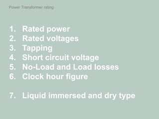
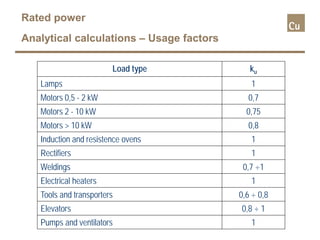
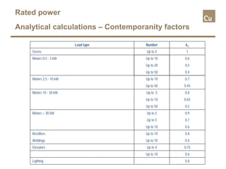
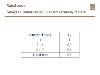
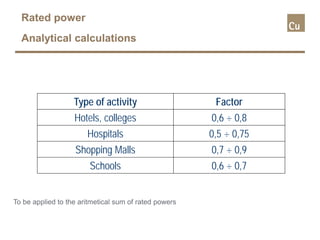
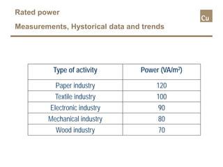
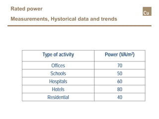

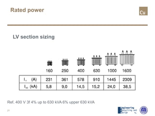
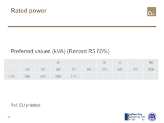
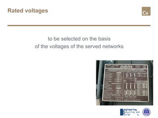
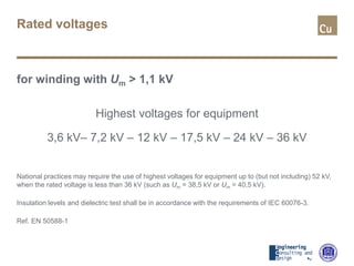
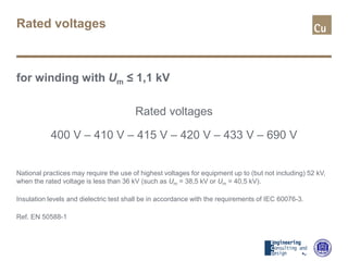

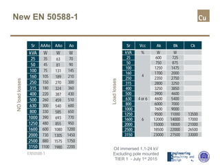
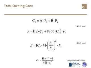
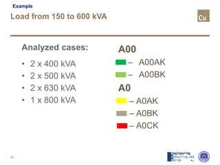
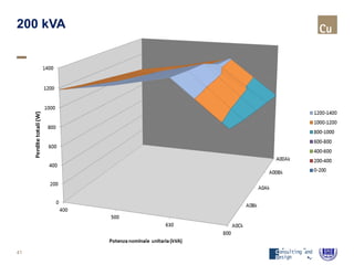
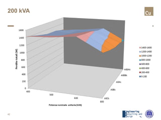
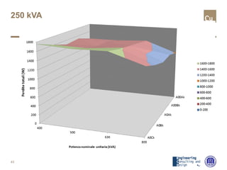
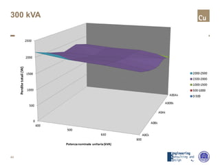
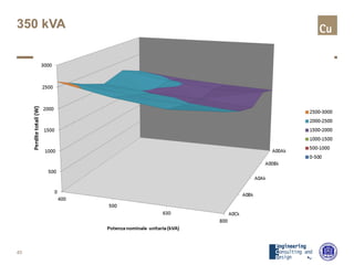
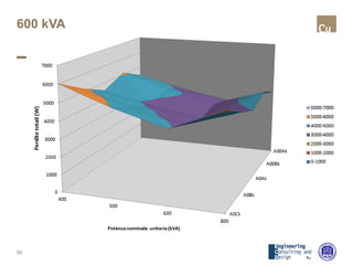

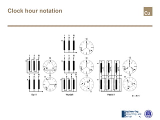
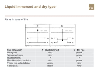


This document discusses power transformer ratings, including rated power, voltages, tapping, short circuit impedance, losses, clock hour notation, and liquid immersed vs dry types. It provides details on calculating rated power based on load power and factors, selecting standard rated voltages, common tapping ranges, choosing short circuit impedance values, and standards for no-load and load losses. It also compares risks of liquid immersed and dry transformers in case of fire.


