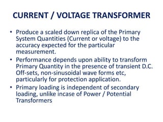
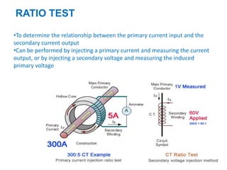
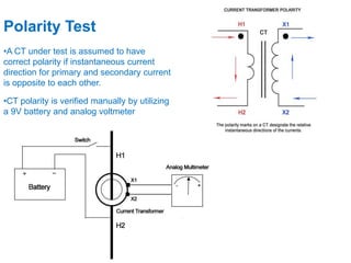
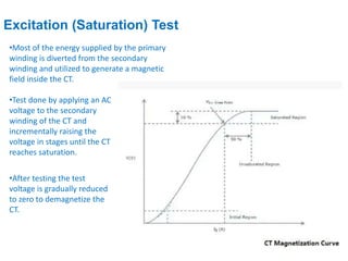
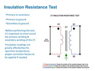
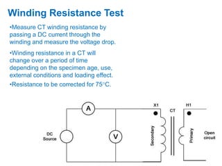
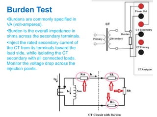
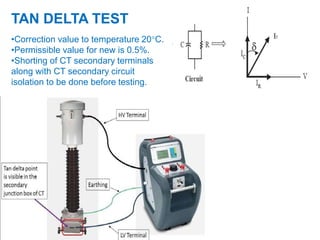
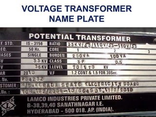
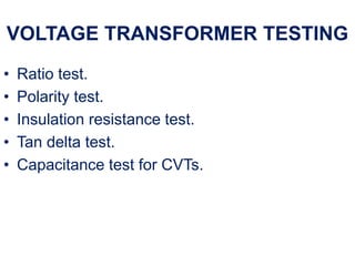
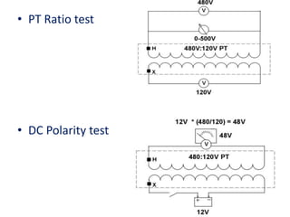
INSTRUMENT TRANSFORMER
CURRENT / VOLTAGE TRANSFORMER
• Produce a scaled down replica of the Primary
System Quantities (Current or voltage) to the
accuracy expected for the particular
measurement.
• Performance depends upon ability to transform
Primary Quantity in the presence of transient D.C.
Off-sets, non-sinusoidal wave forms etc,
particularly for protection application.
• Primary loading is independent of secondary
loading, unlike incase of Power / Potential
Transformers
PROTECTIVE CURRENT TRANSFORMER
• Specified in terms of Accuracy Class, VA Burden & Accuracy
• Limit Factor (ALF) e.g. 5P10, 15 VA.
• Standard Accuracy Class : 5P, 10P, 15P.
• Standard VA Ratings : 5, 10, 15, 30.
• Standard ALF : 5, 10, 15, 20, 30.
• For economical design VA x ALF should not exceed 150.
• Error specified at Rated Current & ALF times Rated Current
• e.g. 5P10, 15 VA CT has a composite error of :
(+/-) 5% at ALF times Rated Current with rated burden
connected
(+/-) 1% at Rated Current with rated burden connected.
• For a given CT, burden & ALF are inversely related
METERING CLASS CURRENT
TRANSFORMER
• Specified in terms of Accuracy Class , VA Rating and
Instrument Security Factor ( e.g. Class 1.0, VA = 15, ISF =
3.0)
• Standard Accuracy Class= 0.1, 0.2, 0.5, 1.0, 3.0, 5.0.
• Error specified at 5 - 120% of Rated Current.
• Higher errors permitted at lower currents. For example,
Class 1.0 CT has a ratio error of:
(+/-) 1 % at 100-120% of Rated Current
(+/-) 1.5% at 20% of Rated current
(+/-) 3% at 5 % of rated current.
• Error specified with 25-100% of Rated Burden connected.
PROTECTION CT SPECIAL PURPOSE
• Designated as Class PS CT(Class X as per BS).
• Used for balanced protections like Differential, REF.
• Specified in terms of :
1. Knee Point Voltage (Vk)
2. CT Secondary Winding Resistance(Rct)
3. Magnetising Current (Im)
Typical Specification : Ratio=200/1A, Vk= 200V, Rct = 2 Ohms,
Im = 30 mA at Vk/2.
• Low reactance type, Turns ratio error limited to 0.25%.
5A CT SECONDARY
• Used where lead burden insignificant (e.g. CTs
used in in-door metal-clad switch-gear or with
high Prim. Rating say10,000/5A).
• Comparatively low peak voltage on CT secondary
open-circuit.
1A CT SECONDARY
• Preferred where CTs are Out-door and lead
resistance high.
• Comparatively high peak voltage when CT
secondary is open circuited.
CT NAME PLATE
Name plate details
• Ratio: Primary to three secondary current ratios
of 300/1.
• Standard : IEC 60044-1 OR IS2705
• Purpose : 1st core for metering, 2nd & 3rd core is
for protection.
• Line volt : Nominal CT operating voltage.
• HSV : Highest RMS line to line system voltage.
• Burden : Maximum allowable apparent power
from the CT.
• BIL : Basic insulation level (36/70/170kv)
• Used to specify the magnitude of the voltage
surge that a transformer can tolerate without any
damage to the windings and live parts.
• The first which is 36kv is similar to HSV which is
the rated line to line voltage under normal steady
operation.
• The second value which is 70kv means the CT can
be operated at 70kv for 1mins at 50Hz.
• The third value which is 170kv means the CT’s
maximum withstandable impulse voltage is
170kv.
Name plate details
• STC : short time current 25KA/3sec.
• RMS value of the primary current which the CT will
withstand both thermally and dynamically without
damage of the winding for 3 seconds with
secondary winding short circuited.
• I Dyn: rated dynamic current - 62.5KA (peak)
• Peak value of the primary current which a current
transformer will withstand without been damaged
electrically from mechanical forces.
• This type of current can be generated when the
breaker closes back to an existing fault i.e. 2.5 times
short circuit current.
Name plate details
• Class of Ins: A
• The type of transformer insulation used in this case
is of class A.
• This can withstand a temperature of up to 105℃.
• Type: O/D, O/C, live tank
• Outdoor oil-filled live tank current transformer.
Name plate details
• I.S.F: <5 - instrument security factor
• Ratio of the instrument limits the primary current
to the rated primary current is less than 5.
• Vk​. (PS core): = >200v
• Defined by knee point voltage of current
transformer Vk and excitation current at Vk/2​​.
Name plate details
Current transformer tests
1.Ratio Test
2.Polarity Test
3. Excitation (Saturation) Test
4. Insulation Resistance Test
5. Winding Resistance Test
6. Burden Test
7. Tan delta test
8. Core identification test.
•To determine the relationship between the primary current input and the
secondary current output
•Can be performed by injecting a primary current and measuring the current
output, or by injecting a secondary voltage and measuring the induced
primary voltage
RATIO TEST
•A CT under test is assumed to have
correct polarity if instantaneous current
direction for primary and secondary current
is opposite to each other.
•CT polarity is verified manually by utilizing
a 9V battery and analog voltmeter
Polarity Test
Excitation (Saturation) Test
•Most of the energy supplied by the primary
winding is diverted from the secondary
winding and utilized to generate a magnetic
field inside the CT.
•Test done by applying an AC
voltage to the secondary
winding of the CT and
incrementally raising the
voltage in stages until the CT
reaches saturation.
•After testing the test
voltage is gradually reduced
to zero to demagnetize the
CT.
Insulation Resistance Test
•Primary to secondary
•Primary to ground
•Secondary to ground
•Before performing the test,
it’s important to short-circuit
the primary winding &
secondary winding of the CT.
•Insulation readings are
greatly affected by the
specimen temperature,
proper correction factors to
be applied if needed.
Winding Resistance Test
•Measure CT winding resistance by
passing a DC current through the
winding and measure the voltage drop.
•Winding resistance in a CT will
change over a period of time
depending on the specimen age, use,
external conditions and loading effect.
•Resistance to be corrected for 75C.
•Burdens are commonly specified in
VA (volt-amperes).
Burden Test
•Burden is the overall impedance in
ohms across the secondary terminals.
•Inject the rated secondary current of
the CT from its terminals toward the
load side, while isolating the CT
secondary with all connected loads.
Monitor the voltage drop across the
injection points.
TAN DELTA TEST
•Correction value to temperature 20C.
•Permissible value for new is 0.5%.
•Shorting of CT secondary terminals
along with CT secondary circuit
isolation to be done before testing.
VOLTAGE TRANSFORMER
NAME PLATE
• The voltage factor is determined by the maximum
operating voltage, which depends on the neutral
system and the voltage transformer primary
winding earthing conditions.
NAME PLATE DETAILS
VOLTAGE FACTOR
VOLTAGE TRANSFORMER TESTING
• Ratio test.
• Polarity test.
• Insulation resistance test.
• Tan delta test.
• Capacitance test for CVTs.
• PT Ratio test
• DC Polarity test
PS CLASS VT LIMITS
• Error limits as per IS 3156-3
• The limits are valid for 5% rated voltage to
voltage multiplied by rated factor and for burden
25% to 100% with 0.8 power factor lagging.
Class Voltage error % Phase displacement
3P ±3 120 minutes
6P ±6 240 minutes
METERING CLASS VT LIMITS
• As per IS 3156-2
• The limits are valid for 80% TO 120% and for
burden 25% to 100% with 0.8 power factor
lagging.
Class Voltage error % Phase displacement
0.1 ±0.1 ±5minutes
0.2 ±0.2 ±10minutes
0.5 ±0.5 ±20minutes
1.0 ±1.0 ±40minutes
3.0 ±3.0 -
CAPACITIVE VOLTAGE TRANSFORMER
•The main components are the capacitor divider, the intermediate step-down transformer
and the series reactor.
•The step-down transformer and series reactors are connected to the intermediate voltage
tap between C1 & C2.
•The series reactor is manufactured so its impedance cancels the impedance of the capacitor;
therefore, the full intermediate voltage is delivered to the terminals of the step-down
transformer, in phase with the primary line voltage.
• The series reactor and primary winding of the step-down transformer are manufactured
with taps to enable ratio and phase angle adjustment. These are factory preset and do not
require alteration after delivery unless a capacitor unit is changed
•The harmonic suppression filter prevents sustained ferroresonance oscillations. It
consists of a resistor in series with a saturable reactor and a parallel resistor. The reactor is
designed to saturate above the highest over-voltage rating to form a loading circuit, which
will dampen sub-harmonic ferroresonant oscillations.
CAPACITIVE VOLTAGE TRANSFORMER

ct pt testing...........................................

  • 1.
  • 2.
    CURRENT / VOLTAGETRANSFORMER • Produce a scaled down replica of the Primary System Quantities (Current or voltage) to the accuracy expected for the particular measurement. • Performance depends upon ability to transform Primary Quantity in the presence of transient D.C. Off-sets, non-sinusoidal wave forms etc, particularly for protection application. • Primary loading is independent of secondary loading, unlike incase of Power / Potential Transformers
  • 3.
    PROTECTIVE CURRENT TRANSFORMER •Specified in terms of Accuracy Class, VA Burden & Accuracy • Limit Factor (ALF) e.g. 5P10, 15 VA. • Standard Accuracy Class : 5P, 10P, 15P. • Standard VA Ratings : 5, 10, 15, 30. • Standard ALF : 5, 10, 15, 20, 30. • For economical design VA x ALF should not exceed 150. • Error specified at Rated Current & ALF times Rated Current • e.g. 5P10, 15 VA CT has a composite error of : (+/-) 5% at ALF times Rated Current with rated burden connected (+/-) 1% at Rated Current with rated burden connected. • For a given CT, burden & ALF are inversely related
  • 4.
    METERING CLASS CURRENT TRANSFORMER •Specified in terms of Accuracy Class , VA Rating and Instrument Security Factor ( e.g. Class 1.0, VA = 15, ISF = 3.0) • Standard Accuracy Class= 0.1, 0.2, 0.5, 1.0, 3.0, 5.0. • Error specified at 5 - 120% of Rated Current. • Higher errors permitted at lower currents. For example, Class 1.0 CT has a ratio error of: (+/-) 1 % at 100-120% of Rated Current (+/-) 1.5% at 20% of Rated current (+/-) 3% at 5 % of rated current. • Error specified with 25-100% of Rated Burden connected.
  • 5.
    PROTECTION CT SPECIALPURPOSE • Designated as Class PS CT(Class X as per BS). • Used for balanced protections like Differential, REF. • Specified in terms of : 1. Knee Point Voltage (Vk) 2. CT Secondary Winding Resistance(Rct) 3. Magnetising Current (Im) Typical Specification : Ratio=200/1A, Vk= 200V, Rct = 2 Ohms, Im = 30 mA at Vk/2. • Low reactance type, Turns ratio error limited to 0.25%.
  • 6.
    5A CT SECONDARY •Used where lead burden insignificant (e.g. CTs used in in-door metal-clad switch-gear or with high Prim. Rating say10,000/5A). • Comparatively low peak voltage on CT secondary open-circuit. 1A CT SECONDARY • Preferred where CTs are Out-door and lead resistance high. • Comparatively high peak voltage when CT secondary is open circuited.
  • 7.
  • 8.
    Name plate details •Ratio: Primary to three secondary current ratios of 300/1. • Standard : IEC 60044-1 OR IS2705 • Purpose : 1st core for metering, 2nd & 3rd core is for protection. • Line volt : Nominal CT operating voltage. • HSV : Highest RMS line to line system voltage. • Burden : Maximum allowable apparent power from the CT.
  • 9.
    • BIL :Basic insulation level (36/70/170kv) • Used to specify the magnitude of the voltage surge that a transformer can tolerate without any damage to the windings and live parts. • The first which is 36kv is similar to HSV which is the rated line to line voltage under normal steady operation. • The second value which is 70kv means the CT can be operated at 70kv for 1mins at 50Hz. • The third value which is 170kv means the CT’s maximum withstandable impulse voltage is 170kv. Name plate details
  • 10.
    • STC :short time current 25KA/3sec. • RMS value of the primary current which the CT will withstand both thermally and dynamically without damage of the winding for 3 seconds with secondary winding short circuited. • I Dyn: rated dynamic current - 62.5KA (peak) • Peak value of the primary current which a current transformer will withstand without been damaged electrically from mechanical forces. • This type of current can be generated when the breaker closes back to an existing fault i.e. 2.5 times short circuit current. Name plate details
  • 11.
    • Class ofIns: A • The type of transformer insulation used in this case is of class A. • This can withstand a temperature of up to 105℃. • Type: O/D, O/C, live tank • Outdoor oil-filled live tank current transformer. Name plate details
  • 12.
    • I.S.F: <5- instrument security factor • Ratio of the instrument limits the primary current to the rated primary current is less than 5. • Vk​. (PS core): = >200v • Defined by knee point voltage of current transformer Vk and excitation current at Vk/2​​. Name plate details
  • 13.
    Current transformer tests 1.RatioTest 2.Polarity Test 3. Excitation (Saturation) Test 4. Insulation Resistance Test 5. Winding Resistance Test 6. Burden Test 7. Tan delta test 8. Core identification test.
  • 14.
    •To determine therelationship between the primary current input and the secondary current output •Can be performed by injecting a primary current and measuring the current output, or by injecting a secondary voltage and measuring the induced primary voltage RATIO TEST
  • 15.
    •A CT undertest is assumed to have correct polarity if instantaneous current direction for primary and secondary current is opposite to each other. •CT polarity is verified manually by utilizing a 9V battery and analog voltmeter Polarity Test
  • 16.
    Excitation (Saturation) Test •Mostof the energy supplied by the primary winding is diverted from the secondary winding and utilized to generate a magnetic field inside the CT. •Test done by applying an AC voltage to the secondary winding of the CT and incrementally raising the voltage in stages until the CT reaches saturation. •After testing the test voltage is gradually reduced to zero to demagnetize the CT.
  • 17.
    Insulation Resistance Test •Primaryto secondary •Primary to ground •Secondary to ground •Before performing the test, it’s important to short-circuit the primary winding & secondary winding of the CT. •Insulation readings are greatly affected by the specimen temperature, proper correction factors to be applied if needed.
  • 18.
    Winding Resistance Test •MeasureCT winding resistance by passing a DC current through the winding and measure the voltage drop. •Winding resistance in a CT will change over a period of time depending on the specimen age, use, external conditions and loading effect. •Resistance to be corrected for 75C.
  • 19.
    •Burdens are commonlyspecified in VA (volt-amperes). Burden Test •Burden is the overall impedance in ohms across the secondary terminals. •Inject the rated secondary current of the CT from its terminals toward the load side, while isolating the CT secondary with all connected loads. Monitor the voltage drop across the injection points.
  • 20.
    TAN DELTA TEST •Correctionvalue to temperature 20C. •Permissible value for new is 0.5%. •Shorting of CT secondary terminals along with CT secondary circuit isolation to be done before testing.
  • 21.
  • 22.
    • The voltagefactor is determined by the maximum operating voltage, which depends on the neutral system and the voltage transformer primary winding earthing conditions. NAME PLATE DETAILS
  • 23.
  • 24.
    VOLTAGE TRANSFORMER TESTING •Ratio test. • Polarity test. • Insulation resistance test. • Tan delta test. • Capacitance test for CVTs.
  • 25.
    • PT Ratiotest • DC Polarity test
  • 26.
    PS CLASS VTLIMITS • Error limits as per IS 3156-3 • The limits are valid for 5% rated voltage to voltage multiplied by rated factor and for burden 25% to 100% with 0.8 power factor lagging. Class Voltage error % Phase displacement 3P ±3 120 minutes 6P ±6 240 minutes
  • 27.
    METERING CLASS VTLIMITS • As per IS 3156-2 • The limits are valid for 80% TO 120% and for burden 25% to 100% with 0.8 power factor lagging. Class Voltage error % Phase displacement 0.1 ±0.1 ±5minutes 0.2 ±0.2 ±10minutes 0.5 ±0.5 ±20minutes 1.0 ±1.0 ±40minutes 3.0 ±3.0 -
  • 28.
  • 29.
    •The main componentsare the capacitor divider, the intermediate step-down transformer and the series reactor. •The step-down transformer and series reactors are connected to the intermediate voltage tap between C1 & C2. •The series reactor is manufactured so its impedance cancels the impedance of the capacitor; therefore, the full intermediate voltage is delivered to the terminals of the step-down transformer, in phase with the primary line voltage. • The series reactor and primary winding of the step-down transformer are manufactured with taps to enable ratio and phase angle adjustment. These are factory preset and do not require alteration after delivery unless a capacitor unit is changed •The harmonic suppression filter prevents sustained ferroresonance oscillations. It consists of a resistor in series with a saturable reactor and a parallel resistor. The reactor is designed to saturate above the highest over-voltage rating to form a loading circuit, which will dampen sub-harmonic ferroresonant oscillations. CAPACITIVE VOLTAGE TRANSFORMER