Downloaded 867 times


![REFERENCE
[1] Daniel W. Hart, Introduction to Power Electronics, Prentice Hall International Inc,
2003.
[2] Robert W. Erickson, “DC-DC Power Converters”, Department of Electrical and
Computer Engineering, University of Colorado
[3] Rashid, M.H., Power Electronics, Circuits, Devices and Applications, Pearson/Prentice
Hall, 2004
[4] Mohan, Undeland & Robbins, Power Electronics – Converters, Applications and
Design, 2nd edition, John Wiley & Sons, 2003.
[5] Datasheet download at www.ic-on-line.net
14](https://image.slidesharecdn.com/assignment3-pwminverter-120716093611-phpapp02/85/pwm-inverter-14-320.jpg)


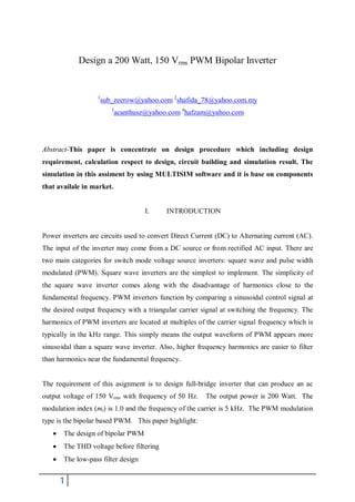
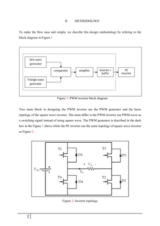
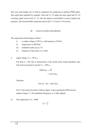
This document outlines the design of a 200 Watt, 150 Vrms PWM bipolar inverter with the following key points: 1. The design process includes calculating component values based on design requirements, building the circuit in Multisim software, and analyzing the simulation results. 2. Key calculations include determining the required DC bus voltage to achieve the 150Vrms AC output voltage despite voltage drops, as well as component sizing based on the given power, modulation index, and carrier frequency specifications. 3. Simulation results show the generated PWM switching signals and the final inverter output voltage matching the desired 150Vrms sinusoidal waveform.