Download as PDF, PPTX

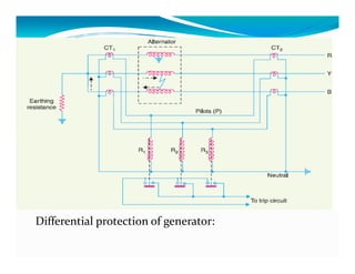
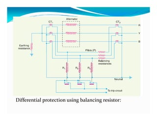
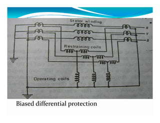
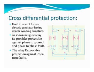
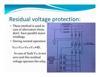
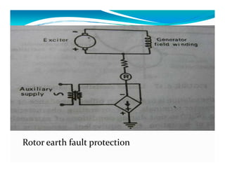
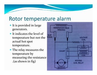
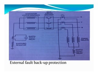


This document discusses generator protection systems. It describes how differential protection uses CTs to detect faults by measuring differences in current. Modified differential protection is discussed as a way to protect the full winding. Other protections mentioned include restricted earth fault protection, stator protection against phase and interturn faults, rotor earth fault protection using dc injection, loss of excitation detection, overload protection using temperature sensors, and negative sequence protection to prevent rotor overheating. The conclusion emphasizes that protective relays act after a fault occurs to ensure safety and equipment protection.


