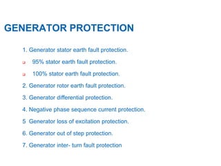
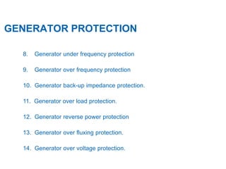
SlideShare a Scribd company logo
GENERATOR PROTECTION
22.07.2015
2
GENERATOR PROTECTION
Generators are designed to run at high load factor for a large
number of years and permit certain incidents of abnormal
working conditions.
The machine and its auxiliaries are supervised by monitoring
device to keep the incidents of abnormal condition down to
minimum.
Despite the monitoring, electrical and mechanical faults may
occurred and generators must be provided with protective relays
which in case of a fault, quickly initiate and disconnect the
machine from the system.
3
GENERATOR PROTECTION
Normal service conditions of generator is supervised by
 Temperature detector such as RTD, temp. gauge etc.
 Mechanical activated device such as vibration pickup,
pressure switches etc.
 Lightning arrestors to limit incoming surges.
Origin of disturbance and failure
 Over voltage.
 Over current.
 Winding Fault in stator and rotor
 Mechanical fault
4
GENERATOR PROTECTION
1. Generator stator earth fault protection.
 95% stator earth fault protection.
 100% stator earth fault protection.
2. Generator rotor earth fault protection.
3. Generator differential protection.
4. Negative phase sequence current protection.
5 Generator loss of excitation protection.
6. Generator out of step protection.
7. Generator inter- turn fault protection
5
GENERATOR PROTECTION
8. Generator under frequency protection
9. Generator over frequency protection
10. Generator back-up impedance protection.
11. Generator over load protection.
12. Generator reverse power protection
13. Generator over fluxing protection.
14. Generator over voltage protection.
6
CLASS – A1 GENERATOR PROTECTION
 Inadvertent Energization
 GCB Breaker Failure
 Voltage Controlled Over Current
 GT Differential Protection
 UT Differential Protection
 WTI and OTI of UT Transformers
 WTI and OTI of GT Transformers
 Buchholz Trip of GT and UT
 PRV Trip of GT and UT
 SPR Trip of GT and UT
 OSR Trip of UT
 REF Protection of UT
 Over Current Protection of GT
 GT Over Hang Differential Protection
CLASS – A2 GENERATOR PROTECTION
 Generator Differential Relay
 Stator Earth fault Relay (100%+95%)
 Generator Reverse Power
 Generator Low Forward Power
 Generator Over Voltage
 Generator Under Frequency Stage 2
 Generator Over Fluxing
 Generator Loss of Excitation
 Generator Rotor Earth Fault
 Generator Excitation System Fault
 I & C Trip
7
CLASS - B GENERATOR PROTECTION
 Generator Under Frequency Stage 1
 Generator Over Frequency
 Generator Backup Impedance
 Negative Sequence Current
 Generator Pole Slip
 Cooling Water Loss
 Conductivity High High
8
9
CLASSIFICATION OF TRIPPING
 Objective is to trip only the essential equipments so that Damage is
minimum, over speeding of set avoided. Impact of large set on the grid is
minimum and time to restart the unit is minimum.
 Class – AII Tripping
 This is adopted for those electrical faults for which tripping cannot be
delayed. This leads to simultaneous tripping of
 -Generator and Field circuit breaker.
 -Turbine tripping.
10
CLASSIFICATION OF TRIPPING
 Class – B Tripping
 This is adopted for all turbine faults (Mechanical) and for some
electrical faults for which it is safe to trip the turbine. Subsequently the
generator is tripped through I & C trip or reverse power interlock.
 Class – A1 Tripping
 This is adopted for all faults beyond the Generator system, which can
be cleared by tripping of EHV circuit breaker alone.
11
STATOR E/F RELAY
 Ground faults, particularly single phase to ground, are the most likely to
occur, particularly on generators equipped with isolated-phase bus
connecting the stator winding terminals to the step-up transformer. Modern
generators are usually STAR -connected with the neutral grounded through a
high resistance to limit the magnitude of the ground fault current.
 A solidly grounded synchronous generator will supply a single phase to
ground short circuit current of about 120% of the three-phase short circuit
current. Since the single phase to ground short circuit is the most likely, an
impedance is usually introduced in the neutral of generators to limit the
ground fault current.
12
STATOR E/F RELAY
 a) 95% Stator Earth Fault Protection
 Ground faults particularly phase to ground are most likely to occur.
generators are grounded through a reactance to limit the current typically
about 10 A.
 The relay is normally set to operate at 5% of maximum neutral voltage
with a time delay of 0.5 sec. with this voltage setting approximately 95% of
stator winding are covered by this protection.
13
STATOR E/F RELAY
 b) 100% Stator E/F Protection:
 As some voltage is required to pickup the 95% E/F relay, approximately
5% of winding remains unprotected. Some time ground faults may occur very
near to the neutral due to mechanical damage and thus 100% protection to
stator winding is required.
 The basic principle is that an external low frequency is injected into the
generator star point. Maximum of 1% of rated generator voltage is injected.
 The voltage/current check unit is used to prevent mal-operation of the
relay at the generator standstill condition.
14
STATOR E/F RELAY
Basic Principle of Voltage Injection into the
Generator Starpoint
15
ROTOR E/F RELAY
 The field or rotor winding of generator is unearthed. Thus single earth fault of
field is not much harmful. But a second earth fault acts as short circuit causing severe
damage to the field winding and mechanically endangers the rotor due to magnetic
unbalance.
 Rotor E/F relay injects a DC voltage to the rotor field winding and measures the
insulation resistance. The protection has two stages, gradual deterioration of the
insulation initiates alarm, a solid earth fault initiates trip.
 Alarm value 5 k Ohm.
 Trip value 1 k Ohm.
16
ROTOR E/F RELAY
17
GEN. DIFFERENTIAL PROTECTION
.
The main protection for generator stator winding is differential
protection. In order to protect generator stator winding from
severe damage during internal faults like phase to phase and
earth faults, a differential current principal is used to detect the
faults.
CTs with identical ratio are used for both neutral and line side
of the generator. Hence under normal service conditions and
external faults with unsaturated CTs the relay operating current
remains almost zero.
18
GEN. DIFFERENTIAL PROTECTION
.
19
NEGATIVE PHASE SEQ. PROTECTION
Unbalanced load protection detects unbalanced loads of three-
phase induction motors. Unbalanced loads create a counter-
rotating field which acts on the rotor at double frequency. Eddy
currents are induced at the rotor surface leading to local
overheating in rotor end zones and slot wedges. Another effect of
unbalanced loads is overheating of the rotor.
Negative sequence current is Produced by due to Load
unbalances i.e.
-Single phase load.
-Transmission line open conductor
-Breaker pole discrepancy etc.
INTERTURN FAULT PROTECTION
20
The interturn fault protection detects faults between turns within a
generator winding (phase). This situation may involve relatively high
circulating currents that flow in the short-circuited turns and damage the
winding and the stator. The protective function is characterized by a high
sensitivity.
Modern medium size and large size turbo generators have the
stator winding designed with only one turn per phase per slot. For these
machines inter-turn faults can only occur in case of double ground faults
or as a result of severe mechanical damage on the stator end winding.
For this type of generator voltage transformers with open delta
can be used to detect interturn fault.
21
.
INTERTURN FAULT PROTECTION
R
Y
B
Vsec Δ=Vpri Δ
R
110/1.732
110/1.732
Setting = 3 V of T= 0.5 Sec
22
.The inadvertent energizing protection serves to limit damage by
accidental connection of the stationary or already started, but not
yet synchronized generator, by fast actuation of the mains
breaker. A connection to a stationary machine is equivalent to
connection to a low-ohmic resistor. Due to the nominal voltage
impressed by the power system, the generator starts up with a
high slip as an asynchronous machine. In this context,
unpermissibly high currents are induced inside the rotor which
may finally destroy it.
INADVERTENT ENERGISATION
23
.
UNDER FREQUENCY PROTECTION
Due to prolong operation of units in case of under freq.
particularly last stage of LP turbine gets damage. Thus an
under frequency Class – B trip is generally provided at 47.5 Hz
after 15 Sec. Under frequency Class AII trip is provided at 47
Hz after 4 Sec. It should also trip the generator circuit breaker;
this is to prevent under frequency operation of loads
connected to the system supplied by the generator.
24
.
OVER FREQUENCY PROTECTION
Prolonged operation of units at higher frequency than rated is
also dangerous to turbine and associated electrical system.
Thus a alarm is generally provided at 51 Hz and trip is
provided at 51.5 Hz.
25
.
LOW IMPEDANCE PROTECTION
Machine impedance protection is used as a selective
time graded protection to provide shortest possible tripping times
for short-circuits in the synchronous machine, on the terminal
leads as well as in the unit transformer. It thus also provides
backup protection functions to the main protection of a power
plant or protection equipment connected in series like generator,
transformer differential and system protection devices.
26
.
OVER LOAD PROTECTION
The power that can be generated is limited by the steam
production and hence cannot rise unnoticed for any
appreciable period above the present value. Over load setting
is done considering the capability of a particular unit and
temperature rise of stator winding.
27
.
REVERSE POWER PROTECTION
The purpose of the reverse power relay is basically to prevent
damage on the prime mover i.e. turbine.
If the driving torque becomes less than the total losses in the
generator and the prime movers, the generator start to work
as a synchronous motor. In case of steam turbine reduction of
the steam flow reduces the cooling effect on the turbine blades
and overheating may occurs.
28
.
OVER VOLTAGE PROTECTION
During start-up of generator, voltage is obtained by automatic
voltage regulator. After synchronization the voltage level of the
generator will dictate voltage of the system grid.
If the generator circuit breaker tripped while machine is running
at full load, increase in the terminal voltage will occur if AVR is
switched to manual control
29
.
OVERFLUXING PROTECTION
The magnetising flux in the core is directly proportional to v/f.
The losses are proportional to the level of excitation and
hence the temperature rise increases.
NORMAL V/F= 110/50=2.2;
FOR 24-1: 2.2*1.15=2.53; V/F=2.53; V=2.53*50; V=126.5(L-L);
V=73.04V (L-E)
FOR 24-1: 2.2*1.2=2.64; V/F=2.64; V=2.64*50; V=132.0(L-L);
V=76.2V (L-E)
30
.
LOSS OF EXCITATION PROTECTION
Under-excitation or a total loss of excitation can result from a short circuit or
open circuit in the excitation circuit, a mal-operation of the automatic
voltage regulator, incorrect control of generators and transformers, or in the
event of a generator connected to a system with capacitive load. In this
context under-excitation means that the excitation of the synchronous
machine is less than required for stable operation at a particular power
level. This excitation limit determines the steady state stability characteristic
of the generator. If the excitation is not sufficient to provide the power
demanded of the generator, then this stability limit is exceeded. The
machine will slip and thereby obtain the required excitation from the
connected three phase system. Depending on the construction of the
generator
31
32
33
34
.
OUT OF STEP PROTECTION
Depending on power network conditions and feeding
generators, dynamic occurrences such as load jumps, short-
circuits not disconnected quickly enough, auto-reclosure
or switching actions, may cause system swings. Such power
swings endanger power network stability. Stability problems often
result from active power swings which can lead to pole-slipping
and generator overloading.
35
36
37
Za = MAX. POWER SWIG FREQUENCY
Zb = TRANSIENT DIRECT AXIS REACTANCE OF THE GENERATOR i.e =
Xd’
Zd-Zc= REACTANCE OF THE NETWORK + REST OF THE
TRANSFORMER
Zc = TRANSFORMER REACTANCE
Zb + Zc = POWER SWING ANGLE BETWEEN GENERATOR AND
TRANSFORMER
Zb + Zd = POWER SWING ANGLE BETWEEN GENERATOR AND
NETWORK
THANKYOU
22.07.2015

More Related Content

What's hot

Operation and maintenance of transformer
Operation and maintenance of transformerOperation and maintenance of transformer
Operation and maintenance of transformer
Kapil Singh
 
Generator protection calculations settings
Generator protection calculations settingsGenerator protection calculations settings
Generator protection calculations settings
michaeljmack
 
Tan delta test for power transformers
Tan delta test for power transformersTan delta test for power transformers
Tan delta test for power transformers
jibinjoy1988
 
Power System Faults and Protection System
Power System Faults and Protection SystemPower System Faults and Protection System
Power System Faults and Protection System
HarshalJain48
 
Power Transformer Protection
Power Transformer ProtectionPower Transformer Protection
Power Transformer Protection
Power System Operation
 
Motor & generator protection example settings
Motor & generator protection example settingsMotor & generator protection example settings
Motor & generator protection example settings
H. Kheir
 
Transformer Differential Protection Setting Calculations
Transformer Differential Protection Setting CalculationsTransformer Differential Protection Setting Calculations
Transformer Differential Protection Setting Calculations
Power System Operation
 
Testing of Transformers.
Testing of Transformers.Testing of Transformers.
Testing of Transformers.
Geetesh Verma
 
Protection & switchgear
Protection & switchgear   Protection & switchgear
Protection & switchgear
johny renoald
 
RELAY CO-ORDINATION WITH FAULT CALCULATION
RELAY CO-ORDINATION WITH FAULT CALCULATIONRELAY CO-ORDINATION WITH FAULT CALCULATION
RELAY CO-ORDINATION WITH FAULT CALCULATIONMd Sarowar Alam
 
Fault Level Calculation
Fault Level CalculationFault Level Calculation
Fault Level CalculationDinesh Sarda
 
Power System Protection course - Part I
Power System Protection course - Part IPower System Protection course - Part I
Power System Protection course - Part I
Slides Hub
 
220 KV Switchyard general overview
220 KV Switchyard general overview220 KV Switchyard general overview
220 KV Switchyard general overview
Thien Huynh
 
Generator Transformer Protections.
Generator Transformer  Protections.Generator Transformer  Protections.
Generator Transformer Protections.
Nischal Popat
 
Power System Protection basics
Power System Protection basicsPower System Protection basics
Power System Protection basics
Rajan Singh Tanwar
 
Tutorial on Distance and Over Current Protection
Tutorial on Distance and Over  Current ProtectionTutorial on Distance and Over  Current Protection
Tutorial on Distance and Over Current Protection
SARAVANAN A
 
Switchgear and protection 1
Switchgear and protection 1Switchgear and protection 1
Switchgear and protection 1
Md Irshad Ahmad
 
Protection & switchgear
Protection & switchgear  Protection & switchgear
Protection & switchgear
johny renoald
 
Transformer overcurrent
Transformer overcurrentTransformer overcurrent
Transformer overcurrent
michaeljmack
 
Transformer tests
Transformer testsTransformer tests
Transformer tests
pandiyarajanc
 

What's hot (20)

Operation and maintenance of transformer
Operation and maintenance of transformerOperation and maintenance of transformer
Operation and maintenance of transformer
 
Generator protection calculations settings
Generator protection calculations settingsGenerator protection calculations settings
Generator protection calculations settings
 
Tan delta test for power transformers
Tan delta test for power transformersTan delta test for power transformers
Tan delta test for power transformers
 
Power System Faults and Protection System
Power System Faults and Protection SystemPower System Faults and Protection System
Power System Faults and Protection System
 
Power Transformer Protection
Power Transformer ProtectionPower Transformer Protection
Power Transformer Protection
 
Motor & generator protection example settings
Motor & generator protection example settingsMotor & generator protection example settings
Motor & generator protection example settings
 
Transformer Differential Protection Setting Calculations
Transformer Differential Protection Setting CalculationsTransformer Differential Protection Setting Calculations
Transformer Differential Protection Setting Calculations
 
Testing of Transformers.
Testing of Transformers.Testing of Transformers.
Testing of Transformers.
 
Protection & switchgear
Protection & switchgear   Protection & switchgear
Protection & switchgear
 
RELAY CO-ORDINATION WITH FAULT CALCULATION
RELAY CO-ORDINATION WITH FAULT CALCULATIONRELAY CO-ORDINATION WITH FAULT CALCULATION
RELAY CO-ORDINATION WITH FAULT CALCULATION
 
Fault Level Calculation
Fault Level CalculationFault Level Calculation
Fault Level Calculation
 
Power System Protection course - Part I
Power System Protection course - Part IPower System Protection course - Part I
Power System Protection course - Part I
 
220 KV Switchyard general overview
220 KV Switchyard general overview220 KV Switchyard general overview
220 KV Switchyard general overview
 
Generator Transformer Protections.
Generator Transformer  Protections.Generator Transformer  Protections.
Generator Transformer Protections.
 
Power System Protection basics
Power System Protection basicsPower System Protection basics
Power System Protection basics
 
Tutorial on Distance and Over Current Protection
Tutorial on Distance and Over  Current ProtectionTutorial on Distance and Over  Current Protection
Tutorial on Distance and Over Current Protection
 
Switchgear and protection 1
Switchgear and protection 1Switchgear and protection 1
Switchgear and protection 1
 
Protection & switchgear
Protection & switchgear  Protection & switchgear
Protection & switchgear
 
Transformer overcurrent
Transformer overcurrentTransformer overcurrent
Transformer overcurrent
 
Transformer tests
Transformer testsTransformer tests
Transformer tests
 

Similar to 442639191-Generator-Protection-ppt.ppt

Generator protection by bhushan kumbhalkar
Generator protection by bhushan kumbhalkarGenerator protection by bhushan kumbhalkar
Generator protection by bhushan kumbhalkar
Bhushan Kumbhalkar
 
Protection Of Generator
Protection Of GeneratorProtection Of Generator
Protection Of Generator
Rahuldey1991
 
class on Protection.pptx
class on Protection.pptxclass on Protection.pptx
class on Protection.pptx
SubhroSen9
 
presentation_generator_protection.pptx
presentation_generator_protection.pptxpresentation_generator_protection.pptx
presentation_generator_protection.pptx
vasan35
 
Generator Protection By - Er Rahul Sharma
Generator Protection By - Er Rahul Sharma Generator Protection By - Er Rahul Sharma
Generator Protection By - Er Rahul Sharma
Rahul Ruddra
 
Generator Protection
Generator ProtectionGenerator Protection
Generator ProtectionPriten Vasa
 
Generator protection
Generator protectionGenerator protection
Generator protectionKeshar Rawal
 
MTA GENERATOR PROTECTION .PPT.pptx
MTA GENERATOR PROTECTION .PPT.pptxMTA GENERATOR PROTECTION .PPT.pptx
MTA GENERATOR PROTECTION .PPT.pptx
rajkumarmaurya31
 
Generator protection
Generator protectionGenerator protection
Generator protection
SSVASAVA
 
Equipment protection
Equipment protectionEquipment protection
Equipment protection
Slides Hub
 
Generator and Transformer Protection (PART 1)
Generator and Transformer Protection (PART 1)Generator and Transformer Protection (PART 1)
Generator and Transformer Protection (PART 1)
Dr. Rohit Babu
 
Generator protection by a. kato
Generator protection by a. katoGenerator protection by a. kato
Generator protection by a. kato
Agrey Kato
 
Generator protection
Generator protectionGenerator protection
Generator protection
Parimal Bhagat
 
Generator protection LEC 2
Generator protection  LEC 2Generator protection  LEC 2
Generator protection LEC 2
Rahaf Waheep
 
An-Overview-of-Protection-System-Analysis-3.pdf
An-Overview-of-Protection-System-Analysis-3.pdfAn-Overview-of-Protection-System-Analysis-3.pdf
An-Overview-of-Protection-System-Analysis-3.pdf
RamprasadSarkar1
 
LECTURE 1 - GENERATOR PROTECTION.pptx
LECTURE 1 - GENERATOR PROTECTION.pptxLECTURE 1 - GENERATOR PROTECTION.pptx
LECTURE 1 - GENERATOR PROTECTION.pptx
LoitaFredy
 
Advanced Generator Ground Fault Protections
Advanced Generator Ground Fault ProtectionsAdvanced Generator Ground Fault Protections
Advanced Generator Ground Fault Protections
Arjay Automation
 
New Microsoft Word Document
New Microsoft Word DocumentNew Microsoft Word Document
New Microsoft Word DocumentBarunava Sikdar
 
Electrical Protection systems in Thermal power stations.ppt
Electrical Protection systems in Thermal power stations.pptElectrical Protection systems in Thermal power stations.ppt
Electrical Protection systems in Thermal power stations.ppt
NarasimhanRengarajan1
 

Similar to 442639191-Generator-Protection-ppt.ppt (20)

Generator protection by bhushan kumbhalkar
Generator protection by bhushan kumbhalkarGenerator protection by bhushan kumbhalkar
Generator protection by bhushan kumbhalkar
 
Protection Of Generator
Protection Of GeneratorProtection Of Generator
Protection Of Generator
 
class on Protection.pptx
class on Protection.pptxclass on Protection.pptx
class on Protection.pptx
 
presentation_generator_protection.pptx
presentation_generator_protection.pptxpresentation_generator_protection.pptx
presentation_generator_protection.pptx
 
Generator Protection By - Er Rahul Sharma
Generator Protection By - Er Rahul Sharma Generator Protection By - Er Rahul Sharma
Generator Protection By - Er Rahul Sharma
 
Generator Protection
Generator ProtectionGenerator Protection
Generator Protection
 
Generator protection
Generator protectionGenerator protection
Generator protection
 
MTA GENERATOR PROTECTION .PPT.pptx
MTA GENERATOR PROTECTION .PPT.pptxMTA GENERATOR PROTECTION .PPT.pptx
MTA GENERATOR PROTECTION .PPT.pptx
 
Generator protection
Generator protectionGenerator protection
Generator protection
 
Equipment protection
Equipment protectionEquipment protection
Equipment protection
 
Generator and Transformer Protection (PART 1)
Generator and Transformer Protection (PART 1)Generator and Transformer Protection (PART 1)
Generator and Transformer Protection (PART 1)
 
Generator protection by a. kato
Generator protection by a. katoGenerator protection by a. kato
Generator protection by a. kato
 
Generator protection
Generator protectionGenerator protection
Generator protection
 
Generator protection LEC 2
Generator protection  LEC 2Generator protection  LEC 2
Generator protection LEC 2
 
An-Overview-of-Protection-System-Analysis-3.pdf
An-Overview-of-Protection-System-Analysis-3.pdfAn-Overview-of-Protection-System-Analysis-3.pdf
An-Overview-of-Protection-System-Analysis-3.pdf
 
LECTURE 1 - GENERATOR PROTECTION.pptx
LECTURE 1 - GENERATOR PROTECTION.pptxLECTURE 1 - GENERATOR PROTECTION.pptx
LECTURE 1 - GENERATOR PROTECTION.pptx
 
Advanced Generator Ground Fault Protections
Advanced Generator Ground Fault ProtectionsAdvanced Generator Ground Fault Protections
Advanced Generator Ground Fault Protections
 
New Microsoft Word Document
New Microsoft Word DocumentNew Microsoft Word Document
New Microsoft Word Document
 
Electrical Protection systems in Thermal power stations.ppt
Electrical Protection systems in Thermal power stations.pptElectrical Protection systems in Thermal power stations.ppt
Electrical Protection systems in Thermal power stations.ppt
 
Protection of alternator
Protection of alternatorProtection of alternator
Protection of alternator
 

Recently uploaded

CFD Simulation of By-pass Flow in a HRSG module by R&R Consult.pptx
CFD Simulation of By-pass Flow in a HRSG module by R&R Consult.pptxCFD Simulation of By-pass Flow in a HRSG module by R&R Consult.pptx
CFD Simulation of By-pass Flow in a HRSG module by R&R Consult.pptx
R&R Consult
 
The role of big data in decision making.
The role of big data in decision making.The role of big data in decision making.
The role of big data in decision making.
ankuprajapati0525
 
Runway Orientation Based on the Wind Rose Diagram.pptx
Runway Orientation Based on the Wind Rose Diagram.pptxRunway Orientation Based on the Wind Rose Diagram.pptx
Runway Orientation Based on the Wind Rose Diagram.pptx
SupreethSP4
 
AKS UNIVERSITY Satna Final Year Project By OM Hardaha.pdf
AKS UNIVERSITY Satna Final Year Project By OM Hardaha.pdfAKS UNIVERSITY Satna Final Year Project By OM Hardaha.pdf
AKS UNIVERSITY Satna Final Year Project By OM Hardaha.pdf
SamSarthak3
 
DESIGN A COTTON SEED SEPARATION MACHINE.docx
DESIGN A COTTON SEED SEPARATION MACHINE.docxDESIGN A COTTON SEED SEPARATION MACHINE.docx
DESIGN A COTTON SEED SEPARATION MACHINE.docx
FluxPrime1
 
space technology lecture notes on satellite
space technology lecture notes on satellitespace technology lecture notes on satellite
space technology lecture notes on satellite
ongomchris
 
一比一原版(SFU毕业证)西蒙菲莎大学毕业证成绩单如何办理
一比一原版(SFU毕业证)西蒙菲莎大学毕业证成绩单如何办理一比一原版(SFU毕业证)西蒙菲莎大学毕业证成绩单如何办理
一比一原版(SFU毕业证)西蒙菲莎大学毕业证成绩单如何办理
bakpo1
 
Sachpazis:Terzaghi Bearing Capacity Estimation in simple terms with Calculati...
Sachpazis:Terzaghi Bearing Capacity Estimation in simple terms with Calculati...Sachpazis:Terzaghi Bearing Capacity Estimation in simple terms with Calculati...
Sachpazis:Terzaghi Bearing Capacity Estimation in simple terms with Calculati...
Dr.Costas Sachpazis
 
H.Seo, ICLR 2024, MLILAB, KAIST AI.pdf
H.Seo,  ICLR 2024, MLILAB,  KAIST AI.pdfH.Seo,  ICLR 2024, MLILAB,  KAIST AI.pdf
H.Seo, ICLR 2024, MLILAB, KAIST AI.pdf
MLILAB
 
Planning Of Procurement o different goods and services
Planning Of Procurement o different goods and servicesPlanning Of Procurement o different goods and services
Planning Of Procurement o different goods and services
JoytuBarua2
 
block diagram and signal flow graph representation
block diagram and signal flow graph representationblock diagram and signal flow graph representation
block diagram and signal flow graph representation
Divya Somashekar
 
J.Yang, ICLR 2024, MLILAB, KAIST AI.pdf
J.Yang,  ICLR 2024, MLILAB, KAIST AI.pdfJ.Yang,  ICLR 2024, MLILAB, KAIST AI.pdf
J.Yang, ICLR 2024, MLILAB, KAIST AI.pdf
MLILAB
 
Water Industry Process Automation and Control Monthly - May 2024.pdf
Water Industry Process Automation and Control Monthly - May 2024.pdfWater Industry Process Automation and Control Monthly - May 2024.pdf
Water Industry Process Automation and Control Monthly - May 2024.pdf
Water Industry Process Automation & Control
 
一比一原版(IIT毕业证)伊利诺伊理工大学毕业证成绩单专业办理
一比一原版(IIT毕业证)伊利诺伊理工大学毕业证成绩单专业办理一比一原版(IIT毕业证)伊利诺伊理工大学毕业证成绩单专业办理
一比一原版(IIT毕业证)伊利诺伊理工大学毕业证成绩单专业办理
zwunae
 
The Benefits and Techniques of Trenchless Pipe Repair.pdf
The Benefits and Techniques of Trenchless Pipe Repair.pdfThe Benefits and Techniques of Trenchless Pipe Repair.pdf
The Benefits and Techniques of Trenchless Pipe Repair.pdf
Pipe Restoration Solutions
 
MCQ Soil mechanics questions (Soil shear strength).pdf
MCQ Soil mechanics questions (Soil shear strength).pdfMCQ Soil mechanics questions (Soil shear strength).pdf
MCQ Soil mechanics questions (Soil shear strength).pdf
Osamah Alsalih
 
Pile Foundation by Venkatesh Taduvai (Sub Geotechnical Engineering II)-conver...
Pile Foundation by Venkatesh Taduvai (Sub Geotechnical Engineering II)-conver...Pile Foundation by Venkatesh Taduvai (Sub Geotechnical Engineering II)-conver...
Pile Foundation by Venkatesh Taduvai (Sub Geotechnical Engineering II)-conver...
AJAYKUMARPUND1
 
Cosmetic shop management system project report.pdf
Cosmetic shop management system project report.pdfCosmetic shop management system project report.pdf
Cosmetic shop management system project report.pdf
Kamal Acharya
 
Student information management system project report ii.pdf
Student information management system project report ii.pdfStudent information management system project report ii.pdf
Student information management system project report ii.pdf
Kamal Acharya
 
HYDROPOWER - Hydroelectric power generation
HYDROPOWER - Hydroelectric power generationHYDROPOWER - Hydroelectric power generation
HYDROPOWER - Hydroelectric power generation
Robbie Edward Sayers
 

Recently uploaded (20)

CFD Simulation of By-pass Flow in a HRSG module by R&R Consult.pptx
CFD Simulation of By-pass Flow in a HRSG module by R&R Consult.pptxCFD Simulation of By-pass Flow in a HRSG module by R&R Consult.pptx
CFD Simulation of By-pass Flow in a HRSG module by R&R Consult.pptx
 
The role of big data in decision making.
The role of big data in decision making.The role of big data in decision making.
The role of big data in decision making.
 
Runway Orientation Based on the Wind Rose Diagram.pptx
Runway Orientation Based on the Wind Rose Diagram.pptxRunway Orientation Based on the Wind Rose Diagram.pptx
Runway Orientation Based on the Wind Rose Diagram.pptx
 
AKS UNIVERSITY Satna Final Year Project By OM Hardaha.pdf
AKS UNIVERSITY Satna Final Year Project By OM Hardaha.pdfAKS UNIVERSITY Satna Final Year Project By OM Hardaha.pdf
AKS UNIVERSITY Satna Final Year Project By OM Hardaha.pdf
 
DESIGN A COTTON SEED SEPARATION MACHINE.docx
DESIGN A COTTON SEED SEPARATION MACHINE.docxDESIGN A COTTON SEED SEPARATION MACHINE.docx
DESIGN A COTTON SEED SEPARATION MACHINE.docx
 
space technology lecture notes on satellite
space technology lecture notes on satellitespace technology lecture notes on satellite
space technology lecture notes on satellite
 
一比一原版(SFU毕业证)西蒙菲莎大学毕业证成绩单如何办理
一比一原版(SFU毕业证)西蒙菲莎大学毕业证成绩单如何办理一比一原版(SFU毕业证)西蒙菲莎大学毕业证成绩单如何办理
一比一原版(SFU毕业证)西蒙菲莎大学毕业证成绩单如何办理
 
Sachpazis:Terzaghi Bearing Capacity Estimation in simple terms with Calculati...
Sachpazis:Terzaghi Bearing Capacity Estimation in simple terms with Calculati...Sachpazis:Terzaghi Bearing Capacity Estimation in simple terms with Calculati...
Sachpazis:Terzaghi Bearing Capacity Estimation in simple terms with Calculati...
 
H.Seo, ICLR 2024, MLILAB, KAIST AI.pdf
H.Seo,  ICLR 2024, MLILAB,  KAIST AI.pdfH.Seo,  ICLR 2024, MLILAB,  KAIST AI.pdf
H.Seo, ICLR 2024, MLILAB, KAIST AI.pdf
 
Planning Of Procurement o different goods and services
Planning Of Procurement o different goods and servicesPlanning Of Procurement o different goods and services
Planning Of Procurement o different goods and services
 
block diagram and signal flow graph representation
block diagram and signal flow graph representationblock diagram and signal flow graph representation
block diagram and signal flow graph representation
 
J.Yang, ICLR 2024, MLILAB, KAIST AI.pdf
J.Yang,  ICLR 2024, MLILAB, KAIST AI.pdfJ.Yang,  ICLR 2024, MLILAB, KAIST AI.pdf
J.Yang, ICLR 2024, MLILAB, KAIST AI.pdf
 
Water Industry Process Automation and Control Monthly - May 2024.pdf
Water Industry Process Automation and Control Monthly - May 2024.pdfWater Industry Process Automation and Control Monthly - May 2024.pdf
Water Industry Process Automation and Control Monthly - May 2024.pdf
 
一比一原版(IIT毕业证)伊利诺伊理工大学毕业证成绩单专业办理
一比一原版(IIT毕业证)伊利诺伊理工大学毕业证成绩单专业办理一比一原版(IIT毕业证)伊利诺伊理工大学毕业证成绩单专业办理
一比一原版(IIT毕业证)伊利诺伊理工大学毕业证成绩单专业办理
 
The Benefits and Techniques of Trenchless Pipe Repair.pdf
The Benefits and Techniques of Trenchless Pipe Repair.pdfThe Benefits and Techniques of Trenchless Pipe Repair.pdf
The Benefits and Techniques of Trenchless Pipe Repair.pdf
 
MCQ Soil mechanics questions (Soil shear strength).pdf
MCQ Soil mechanics questions (Soil shear strength).pdfMCQ Soil mechanics questions (Soil shear strength).pdf
MCQ Soil mechanics questions (Soil shear strength).pdf
 
Pile Foundation by Venkatesh Taduvai (Sub Geotechnical Engineering II)-conver...
Pile Foundation by Venkatesh Taduvai (Sub Geotechnical Engineering II)-conver...Pile Foundation by Venkatesh Taduvai (Sub Geotechnical Engineering II)-conver...
Pile Foundation by Venkatesh Taduvai (Sub Geotechnical Engineering II)-conver...
 
Cosmetic shop management system project report.pdf
Cosmetic shop management system project report.pdfCosmetic shop management system project report.pdf
Cosmetic shop management system project report.pdf
 
Student information management system project report ii.pdf
Student information management system project report ii.pdfStudent information management system project report ii.pdf
Student information management system project report ii.pdf
 
HYDROPOWER - Hydroelectric power generation
HYDROPOWER - Hydroelectric power generationHYDROPOWER - Hydroelectric power generation
HYDROPOWER - Hydroelectric power generation
 

442639191-Generator-Protection-ppt.ppt

  • 2. 2 GENERATOR PROTECTION Generators are designed to run at high load factor for a large number of years and permit certain incidents of abnormal working conditions. The machine and its auxiliaries are supervised by monitoring device to keep the incidents of abnormal condition down to minimum. Despite the monitoring, electrical and mechanical faults may occurred and generators must be provided with protective relays which in case of a fault, quickly initiate and disconnect the machine from the system.
  • 3. 3 GENERATOR PROTECTION Normal service conditions of generator is supervised by  Temperature detector such as RTD, temp. gauge etc.  Mechanical activated device such as vibration pickup, pressure switches etc.  Lightning arrestors to limit incoming surges. Origin of disturbance and failure  Over voltage.  Over current.  Winding Fault in stator and rotor  Mechanical fault
  • 4. 4 GENERATOR PROTECTION 1. Generator stator earth fault protection.  95% stator earth fault protection.  100% stator earth fault protection. 2. Generator rotor earth fault protection. 3. Generator differential protection. 4. Negative phase sequence current protection. 5 Generator loss of excitation protection. 6. Generator out of step protection. 7. Generator inter- turn fault protection
  • 5. 5 GENERATOR PROTECTION 8. Generator under frequency protection 9. Generator over frequency protection 10. Generator back-up impedance protection. 11. Generator over load protection. 12. Generator reverse power protection 13. Generator over fluxing protection. 14. Generator over voltage protection.
  • 6. 6 CLASS – A1 GENERATOR PROTECTION  Inadvertent Energization  GCB Breaker Failure  Voltage Controlled Over Current  GT Differential Protection  UT Differential Protection  WTI and OTI of UT Transformers  WTI and OTI of GT Transformers  Buchholz Trip of GT and UT  PRV Trip of GT and UT  SPR Trip of GT and UT  OSR Trip of UT  REF Protection of UT  Over Current Protection of GT  GT Over Hang Differential Protection
  • 7. CLASS – A2 GENERATOR PROTECTION  Generator Differential Relay  Stator Earth fault Relay (100%+95%)  Generator Reverse Power  Generator Low Forward Power  Generator Over Voltage  Generator Under Frequency Stage 2  Generator Over Fluxing  Generator Loss of Excitation  Generator Rotor Earth Fault  Generator Excitation System Fault  I & C Trip 7
  • 8. CLASS - B GENERATOR PROTECTION  Generator Under Frequency Stage 1  Generator Over Frequency  Generator Backup Impedance  Negative Sequence Current  Generator Pole Slip  Cooling Water Loss  Conductivity High High 8
  • 9. 9 CLASSIFICATION OF TRIPPING  Objective is to trip only the essential equipments so that Damage is minimum, over speeding of set avoided. Impact of large set on the grid is minimum and time to restart the unit is minimum.  Class – AII Tripping  This is adopted for those electrical faults for which tripping cannot be delayed. This leads to simultaneous tripping of  -Generator and Field circuit breaker.  -Turbine tripping.
  • 10. 10 CLASSIFICATION OF TRIPPING  Class – B Tripping  This is adopted for all turbine faults (Mechanical) and for some electrical faults for which it is safe to trip the turbine. Subsequently the generator is tripped through I & C trip or reverse power interlock.  Class – A1 Tripping  This is adopted for all faults beyond the Generator system, which can be cleared by tripping of EHV circuit breaker alone.
  • 11. 11 STATOR E/F RELAY  Ground faults, particularly single phase to ground, are the most likely to occur, particularly on generators equipped with isolated-phase bus connecting the stator winding terminals to the step-up transformer. Modern generators are usually STAR -connected with the neutral grounded through a high resistance to limit the magnitude of the ground fault current.  A solidly grounded synchronous generator will supply a single phase to ground short circuit current of about 120% of the three-phase short circuit current. Since the single phase to ground short circuit is the most likely, an impedance is usually introduced in the neutral of generators to limit the ground fault current.
  • 12. 12 STATOR E/F RELAY  a) 95% Stator Earth Fault Protection  Ground faults particularly phase to ground are most likely to occur. generators are grounded through a reactance to limit the current typically about 10 A.  The relay is normally set to operate at 5% of maximum neutral voltage with a time delay of 0.5 sec. with this voltage setting approximately 95% of stator winding are covered by this protection.
  • 13. 13 STATOR E/F RELAY  b) 100% Stator E/F Protection:  As some voltage is required to pickup the 95% E/F relay, approximately 5% of winding remains unprotected. Some time ground faults may occur very near to the neutral due to mechanical damage and thus 100% protection to stator winding is required.  The basic principle is that an external low frequency is injected into the generator star point. Maximum of 1% of rated generator voltage is injected.  The voltage/current check unit is used to prevent mal-operation of the relay at the generator standstill condition.
  • 14. 14 STATOR E/F RELAY Basic Principle of Voltage Injection into the Generator Starpoint
  • 15. 15 ROTOR E/F RELAY  The field or rotor winding of generator is unearthed. Thus single earth fault of field is not much harmful. But a second earth fault acts as short circuit causing severe damage to the field winding and mechanically endangers the rotor due to magnetic unbalance.  Rotor E/F relay injects a DC voltage to the rotor field winding and measures the insulation resistance. The protection has two stages, gradual deterioration of the insulation initiates alarm, a solid earth fault initiates trip.  Alarm value 5 k Ohm.  Trip value 1 k Ohm.
  • 17. 17 GEN. DIFFERENTIAL PROTECTION . The main protection for generator stator winding is differential protection. In order to protect generator stator winding from severe damage during internal faults like phase to phase and earth faults, a differential current principal is used to detect the faults. CTs with identical ratio are used for both neutral and line side of the generator. Hence under normal service conditions and external faults with unsaturated CTs the relay operating current remains almost zero.
  • 19. 19 NEGATIVE PHASE SEQ. PROTECTION Unbalanced load protection detects unbalanced loads of three- phase induction motors. Unbalanced loads create a counter- rotating field which acts on the rotor at double frequency. Eddy currents are induced at the rotor surface leading to local overheating in rotor end zones and slot wedges. Another effect of unbalanced loads is overheating of the rotor. Negative sequence current is Produced by due to Load unbalances i.e. -Single phase load. -Transmission line open conductor -Breaker pole discrepancy etc.
  • 20. INTERTURN FAULT PROTECTION 20 The interturn fault protection detects faults between turns within a generator winding (phase). This situation may involve relatively high circulating currents that flow in the short-circuited turns and damage the winding and the stator. The protective function is characterized by a high sensitivity. Modern medium size and large size turbo generators have the stator winding designed with only one turn per phase per slot. For these machines inter-turn faults can only occur in case of double ground faults or as a result of severe mechanical damage on the stator end winding. For this type of generator voltage transformers with open delta can be used to detect interturn fault.
  • 21. 21 . INTERTURN FAULT PROTECTION R Y B Vsec Δ=Vpri Δ R 110/1.732 110/1.732 Setting = 3 V of T= 0.5 Sec
  • 22. 22 .The inadvertent energizing protection serves to limit damage by accidental connection of the stationary or already started, but not yet synchronized generator, by fast actuation of the mains breaker. A connection to a stationary machine is equivalent to connection to a low-ohmic resistor. Due to the nominal voltage impressed by the power system, the generator starts up with a high slip as an asynchronous machine. In this context, unpermissibly high currents are induced inside the rotor which may finally destroy it. INADVERTENT ENERGISATION
  • 23. 23 . UNDER FREQUENCY PROTECTION Due to prolong operation of units in case of under freq. particularly last stage of LP turbine gets damage. Thus an under frequency Class – B trip is generally provided at 47.5 Hz after 15 Sec. Under frequency Class AII trip is provided at 47 Hz after 4 Sec. It should also trip the generator circuit breaker; this is to prevent under frequency operation of loads connected to the system supplied by the generator.
  • 24. 24 . OVER FREQUENCY PROTECTION Prolonged operation of units at higher frequency than rated is also dangerous to turbine and associated electrical system. Thus a alarm is generally provided at 51 Hz and trip is provided at 51.5 Hz.
  • 25. 25 . LOW IMPEDANCE PROTECTION Machine impedance protection is used as a selective time graded protection to provide shortest possible tripping times for short-circuits in the synchronous machine, on the terminal leads as well as in the unit transformer. It thus also provides backup protection functions to the main protection of a power plant or protection equipment connected in series like generator, transformer differential and system protection devices.
  • 26. 26 . OVER LOAD PROTECTION The power that can be generated is limited by the steam production and hence cannot rise unnoticed for any appreciable period above the present value. Over load setting is done considering the capability of a particular unit and temperature rise of stator winding.
  • 27. 27 . REVERSE POWER PROTECTION The purpose of the reverse power relay is basically to prevent damage on the prime mover i.e. turbine. If the driving torque becomes less than the total losses in the generator and the prime movers, the generator start to work as a synchronous motor. In case of steam turbine reduction of the steam flow reduces the cooling effect on the turbine blades and overheating may occurs.
  • 28. 28 . OVER VOLTAGE PROTECTION During start-up of generator, voltage is obtained by automatic voltage regulator. After synchronization the voltage level of the generator will dictate voltage of the system grid. If the generator circuit breaker tripped while machine is running at full load, increase in the terminal voltage will occur if AVR is switched to manual control
  • 29. 29 . OVERFLUXING PROTECTION The magnetising flux in the core is directly proportional to v/f. The losses are proportional to the level of excitation and hence the temperature rise increases. NORMAL V/F= 110/50=2.2; FOR 24-1: 2.2*1.15=2.53; V/F=2.53; V=2.53*50; V=126.5(L-L); V=73.04V (L-E) FOR 24-1: 2.2*1.2=2.64; V/F=2.64; V=2.64*50; V=132.0(L-L); V=76.2V (L-E)
  • 30. 30 . LOSS OF EXCITATION PROTECTION Under-excitation or a total loss of excitation can result from a short circuit or open circuit in the excitation circuit, a mal-operation of the automatic voltage regulator, incorrect control of generators and transformers, or in the event of a generator connected to a system with capacitive load. In this context under-excitation means that the excitation of the synchronous machine is less than required for stable operation at a particular power level. This excitation limit determines the steady state stability characteristic of the generator. If the excitation is not sufficient to provide the power demanded of the generator, then this stability limit is exceeded. The machine will slip and thereby obtain the required excitation from the connected three phase system. Depending on the construction of the generator
  • 31. 31
  • 32. 32
  • 33. 33
  • 34. 34 . OUT OF STEP PROTECTION Depending on power network conditions and feeding generators, dynamic occurrences such as load jumps, short- circuits not disconnected quickly enough, auto-reclosure or switching actions, may cause system swings. Such power swings endanger power network stability. Stability problems often result from active power swings which can lead to pole-slipping and generator overloading.
  • 35. 35
  • 36. 36
  • 37. 37 Za = MAX. POWER SWIG FREQUENCY Zb = TRANSIENT DIRECT AXIS REACTANCE OF THE GENERATOR i.e = Xd’ Zd-Zc= REACTANCE OF THE NETWORK + REST OF THE TRANSFORMER Zc = TRANSFORMER REACTANCE Zb + Zc = POWER SWING ANGLE BETWEEN GENERATOR AND TRANSFORMER Zb + Zd = POWER SWING ANGLE BETWEEN GENERATOR AND NETWORK